Our heavyweight helicopter equal in the world does not have
In Rostov started production of the most load-lifting rotary-wing car The Russian holding «Helicopt[...]

Everything about aircrafts and helicopters. News and events in aviation worldwide. Civil, transportation, military helicopters and airplanes.

Everything about aircrafts and helicopters. News and events in aviation worldwide. Civil, transportation, military helicopters and airplanes.

Everything about aircrafts and helicopters. News and events in aviation worldwide. Civil, transportation, military helicopters and airplanes.

Everything about aircrafts and helicopters. News and events in aviation worldwide. Civil, transportation, military helicopters and airplanes.


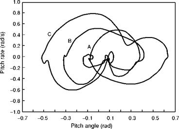
For low speed and hover MTEs, criteria for moderate and large amplitude pitch axis handling qualities mirror the roll axis very closely. The pilot’s ability to manoeuvre is determined by the same performance or agility parameters – control power and attitude quickness. Figure 6.39 illustrates flight results from the DRA research Lynx (Ref. 6.45) performing a quickhop MTE; the aircraft is repositioned from one hover
|
|
A – initial Ав = 11.5°
B – initial Ав = 21.8°
C – initial Ав = 31.5°
Fig. 6.39 Phase plane portraits for Lynx quickhop manoeuvres (Ref. 6.45)
position to another, across a 50-m (150 ft) clearing. The results are displayed as a phase plane portrait with pitch rate plotted against attitude for three different levels of pilot aggressiveness – low, moderate and high, defined by the initial pitch angle and the rate of application of cyclic control. At the highest level of aggressiveness, the pilot is nominally attempting to fly the manoeuvre as quickly as possible, achieving pitch angles of over 30° during the acceleration phase and corresponding rates of 40o/s. Pitch rates of 50°/s were used in the reversal phase of the manoeuvre to initiate the deceleration. In many respects the quickhop is similar to the lateral sidestep described earlier and illustrated in Fig. 6.19. Moreover, in hover, the control power in the pitch axis is essentially the same as in the roll axis, scaled by the ratio of control ranges. This can mean that the pitch axis control power is actually higher than the corresponding roll axis control power. However, there are two handling aspects that serve to differentiate between pitch and roll requirements for control power and quickness. First, the field – of-view constraints resulting from large positive and negative pitch excursions tend to make pilots less willing to use the full agility in the pitch axis. This is coupled with pilot concern of where the tail of the aircraft is; during the quickhop reversal at maximum aggression, for example, the Lynx’s tail rotor descends 10 m (30 ft) closer to the ground. While the same is true for the blade tips in the sidestep, the pilot can more easily monitor the aircraft’s safety as he or she looks into the manoeuvre. Second, to achieve similar quickness levels in pitch and roll, the pilot needs to apply larger control inputs to quicken the pitch response effectively, since the higher inertia in the pitch axis reduces the achievable angular acceleration and hence bandwidth, for the same applied control moments. This can lead to overcontrolling and reduced safety margins
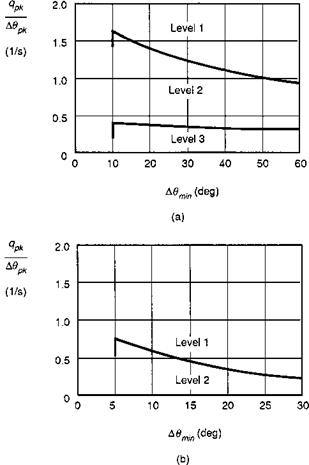
when manoeuvring close to the ground. The result of these effects is that requirements for pitch axis control power and quickness tend to be lower than for roll. Figures 6.40 and 6.41 show the ADS-33 minimum control power and quickness required for rate response types, for the different classes of MTE. Unlike the roll axis criteria shown in Figs 6.15 and 6.17, the pitch criteria are defined only for hover/low-speed MTEs. In forward flight MTEs, ADS-33 is much more qualitative, requiring the pitch authority to be sufficient to accelerate between defined speeds at constant altitude, with no levels of aggressiveness defined.
The minimum control power levels in Fig. 6.40 were developed from flight and simulation experiments conducted on ground-based and in-flight simulators and apply to the cases of aircraft manoeuvring from the hover at the most critical wind state for pitch manoeuvring. They represent the minimum manoeuvre margins for successfully accomplishing battlefield helicopter operations. For moderate amplitude manouevres, the quickness minima in Fig. 6.41 apply. Compared with the roll boundaries, we immediately see the levels are reduced across the range by significant amounts, for the reasons given above. While the rationale for the mismatch between pitch and roll requirements is understandable, when these are realized in practice, the pilot does not have fully harmonized cyclic control; if he or she pushes the cyclic 45° to the right, the aircraft might accelerate away at 70°, simply because the roll quickness is higher than the pitch. The author believes that there is a strong case for full harmonization with rate or attitude response types for low-speed MTEs, as would be found, for example, with TRC (see Section 6.8).
The use of quickness and response to large control inputs to quantify attitude flying qualities at moderate to large amplitude is an innovation of ADS-33 and replaces the earlier measures adopted in MIL-H-8501A and the UK’s Def Stan, based on the attitude response in a defined time, independent of response type. Earlier versions of the ADS, in the original draft Mil Spec 8501B version, did adopt the ‘attitude change in one second’ criterion, but the very compelling and more intuitive quickness, which
|
Fig. 6.41 Pitch attitude quickness criteria (Ref. 6.5): (a) target acquisition and tracking (pitch); (b) general MTEs (pitch) |
had emerged as a natural roll axis handling and agility parameter, soon replaced this for moderate pitch attitude manoeuvres, with excursions between 10° and 30°.
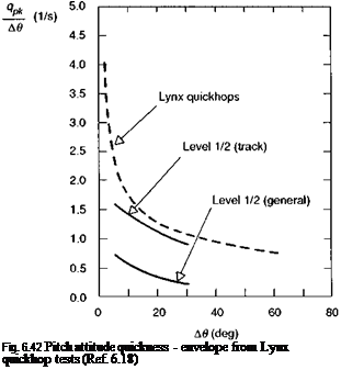
Figure 6.42 shows the Lynx quickness envelope from the DRA Quickhop tests, overlaid with the ADS-33 Level 1/2 boundaries for tracking and general MTEs. The attitude change has been extended out to beyond 60° to include the excursions during the pitch reversal. The quickness, corresponding to the ADS-33 minimum control power requirement at this end of the manoeuvre range, would be about 0.5 rad/s, or approximately half that achieved by the Lynx. A similar result was found with the roll axis sidesteps. The Lynx is a very agile airframe of course, empowered by its hingeless rotor and it does raise the question as to what are the desirable levels, rather than the minimum levels, of quickness for different MTEs. We shall return to this subject under the special topic of agility in Chapter 7. At the lower end of the amplitude range in Fig. 6.42 the measured quickness values rise up to well beyond the minimum requirements; here we are in the domain of the tracking phase of the MTE and we have to look again to the bandwidth criterion to set the standards.
6.4.1
 |
Small amplitude/moderate to high frequency: bandwidth
In the development of pitch handling qualities for fixed-wing aircraft (Ref. 6.6) there has been a history of controversy over the most suitable format for the primary criteria. Most unaugmented or partially augmented aircraft have a characteristic short period pitch mode that dominates the short-term response to elevator, with a frequency that increases with airspeed. The natural parameters associated with this mode are its frequency and damping (f and m), and the response is also shaped by the zero in the numerator (др) of the pitch attitude (0) to elevator (n) transfer function given by
The exponential function has been added to account for any unmodelled time delays or high frequency lags in the aircraft, e. g., actuators with time constant т. Fixed-wing aircraft short-term pitch handling qualities can be established on the basis of the parameter set in the model structure for the short-period mode given above. As discussed in Ref. 6.59, the parameters are used to derive the control anticipation parameter, which is the fundamental manoeuvre margin parameter for fixed-wing aircraft. This so-called LOES approach (Ref. 6.60), whereby the parameters are derived from a model matched to frequency response flight test data, currently enjoys the role of primary criterion for classical response types or essentially where the fit error is small, implying second- order dynamic characteristics. For conventional fixed-wing aircraft, without stability and control augmentation in the pitch axis, the phugoid mode is normally well separated from the short period in frequency terms and the approximation has a wide range
of application. For non-classical response types, or when the fit error is too large to trust the estimated frequency and damping, one of the proposed alternate criteria is bandwidth. The bandwidth and phase delay parameter pair were, in fact, born out of the difficulties encountered in achieving satisfactory equivalent system matching for fixed-wing aircraft with complex, high-order control systems that completely changed the shape of the frequency response and replaced the classical short-period mode with a combination of others.
A discussion of the bandwidth concept formed part of the treatment of roll axis handling qualities in the previous section and this reads across directly to the pitch axis, where for helicopters, bandwidth is no longer the alternate, but primary parameter. Indeed, the need for an alternate to LOES for pitch axis handling of helicopters is even stronger, with typical phugoid and short-period modes much closer together in the frequency range. Research results presented by Houston and Horton (Ref. 6.28) showed that second-order equivalent systems for pitch-heave dynamics in forward flight do have potential, and can be used to simulate the response to limited bandwidth inputs, although not all of the estimated handling parameters reported were physically plausible. The character of the longitudinal modes was discussed in Chapter 4 along with the theoretical framework for linearized models of pitch dynamics.
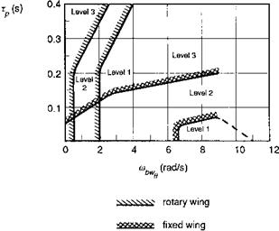
Comparison of the bandwidth/phase delay handling qualities boundaries for fixed – and rotary-wing aircraft are shown in Figs 6.43 and 6.44. Figure 6.43 compares the boundaries for air combat and hover/low-speed tracking tasks, while Fig. 6.44 compares the boundaries for more general rotorcraft MTEs with fixed-wing aircraft in Category C flight phases, including landing. Two points are immediately apparent. The first is that the fixed-wing Level 1/2 boundaries are typically set at bandwidths two to four times those for helicopters. Second, that the phase delay boundaries are set much lower for fixed-wing aircraft. Both of these differences serve to reflect the different character of the rotary – and fixed-wing aircraft MTEs, which in turn is a reflection
|
Fig. 6.43 Pitch attitude bandwidth boundaries – comparison of rotary – and fixed-wing aircraft (Category A flight phases) for air combat and tracking tasks (Refs 6.5, 6.6) |
|
0.2 |
|
0.1 |
of the different speed ranges over which the aircraft operate. It is no coincidence that fixed-wing air combat typically takes place at speeds three to four times those envisaged for rotary-wing aircraft with similar differences in target closure range and rate. Not only is the higher bandwidth required to enable the pilot to track effectively, but the higher speeds in fixed-wing combat provide the aerodynamic forces to achieve the higher bandwidth. It would be very difficult, if not impossible, to engineer the 6 rad/s capability in rotorcraft manoeuvring at 100 knots. The much greater allowed phase delay for rotorcraft is still somewhat controversial, for similar reasons to those discussed for the roll axis. Some research findings have indicated (Refs 6.45, 6.51) that capping of the phase delay boundary down to 200 ms, or even lower, is warranted, and the author has supported this view. However, until a more substantial handling qualities database for pitch axis MTEs is available that clearly demonstrates degraded handling or even PIO tendencies for the higher bandwidth/phase delay configurations, the ADS-33 boundaries will probably be preserved. It should be emphasized that to achieve a phase delay of 300 ms with a 4 rad/s bandwidth, the manufacturer would be working very hard and incorporating very unusual features in the design; in fact, it seems a highly unlikely, if not impossible, practical combination. With the application of digital flight controls to helicopters, however, the controversial issue of phase delay limits for pitch axis dynamics may well re-emerge.
6.4.2 Small amplitude/low to moderate frequency: dynamic stability
The lack of natural longitudinal stability in helicopters was highlighted in Chapter 2 as one of the significant differences between fixed – androtary-wing aircraft; this particular aspect was also discussed in some detail in Chapter 4, where approximate theoretical models provided some insight into the physical mechanisms – the pitching moments due to incidence and speed – that cause the unstable behaviour. The unstable mode
|
Level 2 (FW)
|
0.6 -0.4 -0.2 0.2 0.4 0.6
M 1/s)
S / / / rotary-wing handling boundaries (fully attended flight)
——— rotary-wing handling boundaries (divided attention)
Fig. 6.45 Stability of long-period pitch oscillations – comparison of rotary – and fixed-wing
requirements (Refs 6.5, 6.6)
of an unaugmented helicopter is often referred to as the phugoid, for both hover and forward flight, even though the character of the mode is significantly different in the two speed regimes. As discussed in Chapter 4, for some configurations the ‘phugoid’ frequency reduces to zero in high-speed flight and the motion can become so divergent that the main influence is on short-term control response rather than long-term stability per se.
We reproduce Fig. 2.39 here for the reader’s convenience as Fig. 6.45, showing a comparison of fixed – and rotary-wing handling qualities boundaries on the frequency/damping plane for the long-period mode. The rotary-wing requirements are taken from ADS-33 and strictly apply only to RC response types, but criteria in Def Stan 970 and the civil standards are very similar. The dashed boundary, corresponding to a damping ratio of 0.35, applies to cases where the pilot is required to divide his or her attention between tasks and for flight in degraded visual environments. For fully attended operations, a small amount of instability is allowed, but this is curtailed abruptly for frequencies above 0.5 rad/s. An interesting comparison with the fixed-wing boundaries is the presence of the shaded region where a Level 1 rotarywing aircraft handling corresponds to worse than Level 3 handling for a fixed-wing
|
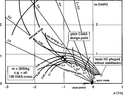
Fig. 6.46 BK117 at 130 knots cruise – influence of pitch rate and attitude feedback gains on phugoid mode (Ref. 6.61) |
aircraft. Also, for frequencies above 0.5 rad/s, there is a large region where Level 1 rotary-wing handling coincides with Level 2 fixed-wing handling. We shall discuss the first of these observations only, which appears to be quite anomalous. It has to be recognized that in the development of new flying qualities requirements, any new criterion should not immediately exclude existing operational aircraft (unless there is very good reason to), and the allowance of the region of instability on Fig. 6.45 conforms with this philosophy. On the other hand, the requirement for the 0.35 damping indicates that if any ‘serious’ mission-related flying is to be conducted, then some form of artificial stability and control augmentation is mandatory. This is exactly how designs evolve in practice, and typically a significant proportion of the development flying on a new type will be dedicated to the refinement of the stability and control augmentation system, with particular emphasis on longitudinal handling. Figure 6.46 shows how the phugoid mode of the BK117 helicopter at 130 knots was stabilized with a combination of rate and attitude feedback with the relatively low gain values -0.06°/° s and 0.3°/°, with the attitude stabilization providing by far the strongest contribution
(Ref. 6.61).
A pulse input in longitudinal cyclic is usually sufficient to excite the pitch long period oscillation; the period can lie between 10 and 30 s, or even higher, hence the motion will have to be allowed to develop over a long time to obtain good estimates of both damping and frequency. As discussed in Chapter 2, this can lead to large amplitude motions from which the recovery can be even more dramatic than the test manoeuvre itself. The lesson is to apply a small amplitude exciting pulse, and to ensure that the motion does not exceed the normal linear range (e. g., attitude excursions < 10°, speed excursions <10 knots).
6.4.4 Trim and quasi-static stability
A pilot flying under IFR in turbulent conditions will have his or her workload significantly increased if, in attempting to control speed errors with cyclic, the new stick position to trim is in the opposite sense to that initially required to cancel the perturbation. Likewise, when manoeuvring to avoid obstacles, a pilot will need to work harder if having rolled into a turn and pulled back on cyclic to increase turn rate, the pilot finds that he or she needs to push forward to avoid ‘digging-in’. Both of these handling characteristics, are, generally speaking, unacceptable by any military or civil requirements standards, and flight tests need to be performed to establish if they are present within the OFE. They represent negative margins of speed and manoeuvre stability, respectively, that, together with their close companion flight path stability, form the topic of this section. Requirements tend to be very qualitative for trim and static/manoeuvre stability and therefore the emphasis below is on the required flight test techniques.
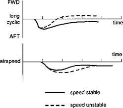
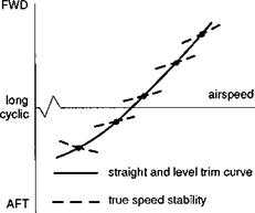
Figure 6.47 illustrates the consequences of positive and negative speed stability for cyclic control — in both cases the speed excursion is the same, but, with negative speed stability, the cyclic retrims the ‘wrong way’. There are two concepts traditionally associated with this characteristic, namely, apparent and true speed stability. The apparent speed stability is determined by the slope of the longitudinal cyclic trim variation with speed, i. e., with collective varying to maintain level flight or a defined rate of climb or descent. True speed stability, on the other hand, usually of more concern to the pilot, is determined at a given speed by noting the new trim stick position for speed increments at constant collective pitch. The two results are sketched in Fig. 6.48 where, for illustration, the true speed stability is shown to be negative and contrary to the apparent speed stability at the lower speed trim condition.
The test technique to investigate true speed stability is fairly straightforward. Having established trimmed flight at a defined airspeed and power setting, the helicopter is retrimmed in a series of speed increments, below and above the test airspeed, with cyclic. Alternation between positive and negative increments allows the aircraft to remain within a sensible altitude band (e. g., 1000 ft) for level flight airspeed tests.
|
Fig. 6.47 Effects of speed stability; impact on cyclic trim (Ref. 6.62) |
|
Fig. 6.48 Effects of speed stability; true and apparent speed stability (Ref. 6.62) |
For climb and descent conditions, two passes through the required altitude band are typically required. While conducting these tests, the pilot will also be concerned with any related ‘ease of trimming’ issues, e. g., controller breakout forces and force gradients. Particular attention will be paid to identifying strong nonlinearities, for example, discontinuities in the speed stability and to distinguishing these from any adverse controller force characteristics or the effects of atmospheric disturbances.
Most certification requirements allow a limited degree of speed instability at low speeds, on the basis that the effect is not so critical here with the pilot normally controlling both speed and flight path angle with a combined cyclic/collective control strategy. At higher speeds, particularly for cold weather operations, adverse speed stability can limit the safe maximum flight speed, and careful testing is required to highlight any advancing blade Mach number effects. One such problem arises when a forward speed increment results in the centre of pressure moving further aft on the outboard sections of the advancing blade. This compressibility effect twists the blade cyclically to give a nose-down pitching moment on the aircraft, which needs to be counteracted with aft cyclic.
Within the framework of the linearized stability theory discussed in Chapter 4, the speed stability of a helicopter is determined by the value of the effective derivative
Zu
M* = Mu – -*Mw (6.24)
Zw
obtained from the equations for the initial pitching moment due to a speed disturbance and the final steady-state cyclic increment. The effect is usually dominated by the pitching moment derivative Mu which has a stabilizing contribution from the main rotor. The fuselage and tailplane contributions will depend upon the trimmed incidence of these components. Tailplane effects can dominate in some situations. Reference 6.63 describes the adverse effect on speed stability caused by tailplane stall during climbing flight in the SA 365N helicopter. Fitting small trailing edge strips on the tailplane attenuated this effect, but to guarantee speed stability for steep climbs in the range 80-100 knots, an additional speed hold function was incorporated into the autopilot. Similar small design modifications to the tailplane leading and trailing edges were required to achieve speed stability for the BK117 helicopter (Ref. 6.61).
In addition to the speed stability testing described above, further tests are required to explore the cyclic trim changes with power settings at different speeds from autorotation to max power climb. These tests are required largely to check that adequate control margins are available in these conditions but will also highlight the essential features of flight path stability. Although there are no general requirements concerned with helicopter flight path stability, for aircraft roles that demand precise flight path control, e. g., guided approaches, testing will need to be carried out to establish the optimum pilot control strategy for the various flight phases. Such tests are likely to be carried out in conjunction with the development of the associated displays and stability augmentation. Collective is, of course, the natural control to counteract flight path errors, but above the minimum power speed the use of cyclic can achieve a similar effect. If the aircraft has, for example, fallen below the glide path and is flying too fast, pulling back on the stick will eventually cancel both errors. Problems arise below minimum power speed where, although the initial effect of pulling back on the stick is to climb the aircraft, the new equilibrium state will be an increased rate of descent. Although normal control strategy should preclude such problems under ‘controlled’ approach conditions, for unguided steep approaches or emergency situations the pilot needs to be aware of the potential problems. At very steep descent angles the problem can be exacerbated by power settling effects (Ref. 6.64) and ultimately the vortex-ring condition (see Section 6.5), where static stability characteristics are overshadowed by dynamic effects.
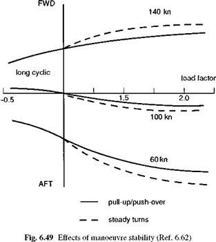
While speed and flight path stability are concerned essentially with cyclic to trim requirements in 1 g flight, manoeuvre stability is related to cyclic changes required in manoeuvres involving a change in normal acceleration, or the stick displacement (or force) per g. All handling requirements specify that this should be positive, i. e., aft stick is required to hold an increased load factor, and as a consequence, there should be no tendency to ‘dig in’ during turning flight. The manoeuvre stability can be determined in flight from either symmetric pull-up and push-over manoeuvres or steady turns, and needs to be measured across the full range of operational conditions, i. e., speeds, atmospheric conditions, aircraft loading. For the pull-up tests, the aircraft is trimmed in level flight at the test airspeed. With collective fixed, the aircraft is then decelerated with cyclic and then dived to accelerate back to the test airspeed. As the test speed is approached, an aft cyclic step is applied to achieve the desired load factor and airspeed as the aircraft passes through a level attitude. The test is repeated with increasing increments of aft cyclic until the maximum permitted load factor is achieved. Similar tests are performed to establish the manoeuvre margin for load factors less than 1, using the push-over technique. For steady turn tests, the aircraft is again trimmed in level flight at the test airspeed. Load factor is applied incrementally by increasing bank angle at constant collective and airspeed, and maintaining balance with pedals. Cyclic is retrimmed at each test condition and the tests conducted for both left and right turns. Rotorspeed should be adjusted only to remain within power-on limits, and since high rates of descent may be achieved, care should be taken to remain within a defined altitude band (e. g., +1000 ft of test condition).
Figure 6.49 illustrates results that may be derived from these tests; the manoeuvre stability is deliberately shown to be negative (and therefore not Level 1) at the higher speed. The cyclic to trim variation with load factor in the steady turn will typically be steeper than the corresponding pull-up result on account of the increased pitch rate in a turn for a given load factor. The relationship between cyclic to trim and pitch
 |
rate or load factor can be derived from linearized theory (see Chapter 4) in the form, neglecting flight path angle effects,
For pull-ups:
Here 01s is the applied cyclic pitch (positive aft), q the pitch rate, V the flight speed and n the load factor. The stability and control derivatives will themselves vary with rotor thrust and rotor disc incidence, and a more exact analysis will certainly be required for higher values of n. Nevertheless, eqns 6.25 and 6.27 are valid representations of manoeuvre stability parameters. The numerator in eqn 6.25 is the classical manoeuvre margin parameter that should be positive for ‘stability’ and acceptable handling characteristics. Typically, an increasingly positive Mw variation with speed will lead to a
deterioration in manoeuvre stability to the point where the margin can change sign. The load factor parameter in the manoeuvre margin for steady turns arises from the inclination of the weight component from the fuselage normal and, at low bank angles, will serve to reduce any undesirable effects of a positive Mw. At higher bank angles, however, any unstable tendencies are likely to re-emerge.
The tests described above to establish the manoeuvre margin are carried out at constant collective pitch settings. In many practical situations, however, the pilot will use collective in conjunction with cyclic to maintain height. The pitching moment generated by collective application will be nose up and hence the cyclic position to trim will be further forward than indicated by the tests at constant collective unless control interlinks have been built in. This effect can be compounded by an increased download on the tail from the main rotor downwash. On other occasions, the pilot may choose to decelerate the aircraft in the turn, hence requiring increased aft cyclic displacement. This variability of stick position with load factor, depending on the type of manoeuvre flown, does not provide the pilot with a reliable tactile cue in manoeuvres. In any case, stick force per g is of more concern to the pilot, particularly in the midhigh speedband, and several current operational helicopters (e. g., AH-64, SH-60) have force feel systems that provide a positive and reliable cue to the pilot of manoeuvre margin.