Our heavyweight helicopter equal in the world does not have
In Rostov started production of the most load-lifting rotary-wing car The Russian holding «Helicopt[...]

Everything about aircrafts and helicopters. News and events in aviation worldwide. Civil, transportation, military helicopters and airplanes.

Everything about aircrafts and helicopters. News and events in aviation worldwide. Civil, transportation, military helicopters and airplanes.

Everything about aircrafts and helicopters. News and events in aviation worldwide. Civil, transportation, military helicopters and airplanes.

Everything about aircrafts and helicopters. News and events in aviation worldwide. Civil, transportation, military helicopters and airplanes.


7.2 Trim
The general principle of flight with any aircraft is that the aerodynamic, inertial and gravitational forces and moments about three mutually perpendicular axes are in balance at all times. In helicopter steady flight (non-rotating), the balance of forces determines the orientation of the main rotor in space. The balance of moments about the aircraft centre of gravity (CG) determines the attitude adopted by the airframe and when this balance is achieved, the helicopter is said to be trimmed. To a pilot the trim may be ‘hands on’ or ‘hands off’; in the latter case, in addition to zero net forces and moments on the helicopter the control forces are also zero: these are a function of the internal control mechanism and will not concern us further, apart from a brief reference at the end of this section.
In deriving the performance equation for forward flight in Chapter 5 (Equation 5.70), the longitudinal trim equations were used in their simplest approximate form (Equations 5.66 and 5.67). They involve the assumption that the helicopter parasite drag is independent of fuselage attitude, or alternatively that Equation 5.70 is used with a particular value of DP for a particular attitude, which is determined by solving a moment equation (see Figures 8.2a-c and the accompanying description below). This procedure is adequate for many performance calculations, which explains why the subject of trim was not introduced at that earlier stage. For the most accurate performance calculations, however, a trim analysis programme is needed in which the six equations of force and moment are solved simultaneously, or at least in longitudinal and lateral groups, by iterative procedures such as Stepniewski and Keys (Vol. II) have described.2
Consideration of helicopter moments has not been necessary up to this point in the book. To go further we need to define the functions of the horizontal tailplane and vertical fin and the nature of direct head moment.
1 This chapter makes liberal use of unpublished papers by B. Pitkin, Flight Mechanics Specialist, Westland Helicopters.
2 An illustration of the complexities introduced when a full 6 degree of freedom analysis is taken is the role of the tail rotor. It will be producing a thrust to balance the torque provided by the engine(s) to power the main rotor. This thrust will be a side force which will need to be reacted by a change in the lateral tilt of the main rotor disc. Hence the main and tail rotors have a mutual influence.
Basic Helicopter Aerodynamics, Third Edition. John Seddon and Simon Newman. © 2011 John Wiley & Sons, Ltd. Published 2011 by John Wiley & Sons, Ltd.
|
|
In steady cruise the function of a tailplane is to provide a pitching moment to offset that produced by the fuselage and thereby reduce the net balancing moment which has to be generated by the rotor. The smaller this balancing moment can be, the less is the potential fatigue damage on the rotor. In transient conditions the tailplane pitching moment is stabilizing, as on a fixed-wing aircraft, and offsets the inherent static instability of the fuselage and to some extent that of the main rotor. A fixed tailplane setting is often used, although this is only optimum (fuselage attitude) for one combination of flight condition and CG location.
A central vertical fin is multi-functional: it generates a stabilizing yawing moment and also provides a structural mounting for the tail rotor. The central fin operates in a poor aerodynamic environment, as a consequence of turbulent wakes from the main and tail rotors and blanking by the fuselage, but fin effectiveness can be improved by providing additional fin area near the tips of the horizontal tailplane.[6]
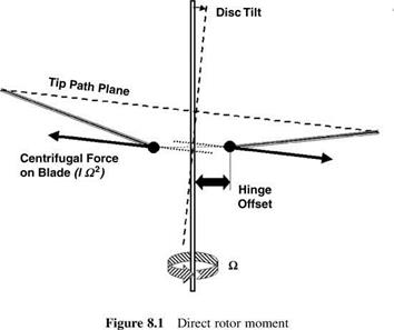
When the flapping hinge axis is offset from the shaft axis (the normal condition for a rotor with three or more blades), the centrifugal force on a blade produces (Figure 8.1) a pitching or rolling moment proportional to disc tilt. Known as direct rotor moment, the effect is large because, although the moment arm is small, the centrifugal force is large compared with the aerodynamic and inertial forces.[7] A hingeless rotor produces a direct moment perhaps four times that of an articulated rotor for the same disc tilt. Analytically this would be expressed by, according to the flexible element, an effective offset four times the typical 3-4% span offset of the articulated hinge.
Looking now at a number of trim situations, in hover with zero wind speed the rotor thrust is vertical in the longitudinal plane, with magnitude equal to the helicopter weight corrected for fuselage downwash. For accelerating away from hover the rotor disc must be inclined forward and the thrust magnitude adjusted so that it is equal to, and directly opposed to, the vector sum of the weight and the inertial force due to acceleration. In steady forward flight the disc is inclined forward and the thrust magnitude is adjusted so that it is equal to, and directly opposed to, the vector sum of the weight and aerodynamic drag.
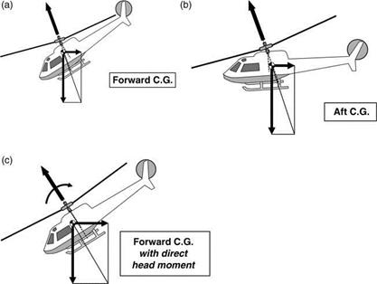
The pitch attitude adopted by the airframe in a given flight condition depends upon a balance of pitching moments about the CG. Illustrating firstly without direct rotor moment or tailplane and airframe moment, the vector sum of aircraft drag (acting through the CG) and weight must lie in the same straight line as the rotor force. This direction being fixed in space, the attitude of the fuselage depends entirely upon the CG position. With reference to Figures 8.2a and b, a forward location results in a more nose-down attitude than an aft location. The effect of a direct rotor moment is illustrated in Figure 8.2c for a forward CG location. Now the rotor thrust and resultant force of drag and weight, again equal in magnitude, are not in direct line but must be parallel, creating a couple which balances the other moments. A similar situation exists in the case of a net moment from the tailplane and airframe. For a given forward CG position, the direct moment makes the fuselage attitude less nose-down than it would otherwise be. Reverse results apply for an aft CG position. At high forward speeds, achieving a balanced state may involve excessive nose-down attitudes unless the tailplane can be made to supply a sufficient restoring moment.
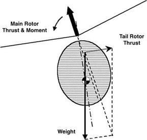
Turning to the balance of lateral forces, in hover the main rotor thrust vector must be inclined slightly sideways to produce a force component balancing the tail rotor thrust. This results in a hovering attitude tilted 2° or 3° to port (Figure 8.3). In sideways flight the tilt is modified to balance sideways drag on the helicopter: the same applies to hovering in a crosswind. In forward flight the option exists, by sideslipping to starboard, to generate a sideforce on
|
Figure 8.2 Fuselage attitude in forward flight: (a) forward CG; (b) aft CG; (c) forward CG with direct head moment |
|
Figure 8.3 Lateral tilt in hover |
the airframe which, at speeds above about 50 knots, will balance the tail rotor thrust and allow a zero-roll attitude to be held.
With the lateral forces balanced in hover, the projection of the resultant of helicopter weight and tail rotor thrust will not generally pass through the main rotor centre, so a rolling couple is exerted which has to be balanced out by a direct rotor moment. This moment depends upon the angle between disc axis and shaft axis and since the first of these has been determined by the force balance, the airframe has to adopt a roll attitude to suit. For the usual situation, in which the line of action of the sideways thrust component is above that of the tail rotor thrust, the correction involves the shaft axis moving closer to the disc axis; that is to say, the helicopter hovers with the fuselage in a small left-roll attitude. Positioning the tail rotor high (close to hub height) minimizes the amount of left-roll angle needed.
Yawing moment balance is provided at all times by selection of the tail rotor thrust, which balances the combined effects of main rotor torque reaction, airframe aerodynamic yawing moment due to sideslip and inertial moments present in manoeuvring.
The achievement of balanced forces and moments for a given flight condition is closely linked with stability. An unstable aircraft theoretically cannot be trimmed, because the slightest disturbance, atmospheric or mechanical, will cause it to diverge from the original condition. A stable aircraft may be difficult to trim because, although the combination of control positions for trim exists, over-sensitivity may make it difficult to introduce any necessary fine adjustments to the aerodynamic control surfaces.