Lifting Line(s) in Close Proximity to the Ground
10.4.1 A Single Lifting Line in the Extreme Ground Effect
The following example illustrates the application of the same technique to the integrodifferential equation of the lifting line in the ground effect. Assuming for simplicity that the longitudinal curvature of the wing’s sections is zero, we can write the lifting line equation in the presence of the ground in the form2
where r(z) is the distribution of the circulation of the lifting line spanwise, C(z) and 6(z) are spanwise distributions of the local chord and angle of pitch,[61] l is the relative span (span to chord ratio), and h = h/l is the height to span ratio. The planform function C(z) is normalized so that
і
C(z)dz = l. (10.25)
Exploring the limit h —» 0 for the flow around a lifting line near the ground, note that using the concept of a lifting line implies that the chord of the wing is much less than the ground clearance and the latter is much less than the wing span.
Thus, the limiting result will be different from that, obtained in the large aspect ratio limit from our previous analysis in Section 3. In the latter case, the distance from the ground is much smaller than the chord, and the chord is much smaller than the span.
|
d2r(z)-| dz2 |
Quadruplicating the integral part of equation (10.24), we obtain the following ordinary differential equation of the second order:
Equation (10.26) should be solved with boundary conditions of zero loading at the tips of the wing, i. e, Г(± 1) = 0. Suppose that 6(z) = в is constant, i. e., the wing is flat.
Consider first the case of a constant chord C(z) = 1 (rectangular wing), for which the resulting expressions for the distribution of the circulation along the lifting line and lift coefflcient can be obtained as
^-«(1-^). (Ю.27)
Recalling that the induced downwash in the extreme ground effect is proportional to the second derivative of the circulation with respect to the spanwise coordinate z, i. e.,
oii(z) = (10.28)
we can derive the induced drag coefficient for a rectangular wing of large aspect ratio in the extreme ground effect in the form
![]() 7t02 sinh 2p — 2p p cosh2p + l
7t02 sinh 2p — 2p p cosh2p + l
As in Prandtl’s classical lifting line theory, the induced drag coefficient can be shown to be proportional to the square of the lift coefficient. We can write
![]() C2 Aeff 4(cosh2p + 1 )(p — tanhp)2
C2 Aeff 4(cosh2p + 1 )(p — tanhp)2
тгХр ’ ^ A A p (sinh 2p — 2p)
Examining equation (10.28), we can conclude that in the extreme ground effect, the optimal[62] spanwise distribution of loading for a wing of a large aspect ratio is parabolic rather than elliptic, as in the unbounded fluid case. As follows from (10.26), for a flat untwisted wing, the spanwise chord distribution securing a parabolic loading distribution is also parabolic. Substituting C(z) = к (1 — z2) (where from normalization condition (10.25), к = 3/2, A = 3Z/2), and r(z) = ro(z2 — 1) the equation (10.26) we obtain the following formula for Г0:
![]() = 2пв 0 /(1 4- 4тгhi/l) ‘
= 2пв 0 /(1 4- 4тгhi/l) ‘
To obtain the lift coefficient based on the chord, we have to apply the following formula: л « д
Су = Г01 (1 – z2)dz = ———————– 7. (10.32)
•’-і ЗМ+47г/іі/Л
The downwash corresponding to parabolic spanwise loading is constant along the lifting line. Simple calculation shows that
![]() . . . d2Г, . rtl _ Shine
. . . d2Г, . rtl _ Shine
",W = -‘‘l d? W = ~2кЛ = ~ 1(1+ 4nVO’
|
3 21 y or, rewriting (10.34) in the Prandtl’s format,[63] Aeff 4 |
The induced drag coefficient of the optimal lifting line is calculated as the lift coefficient times the induced drag, i. e.,
 |
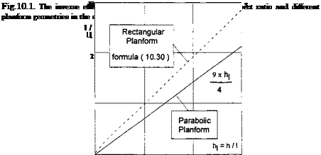
These results show that in the limiting flow problem of a lifting line in the extreme ground effect, the effective aspect ratio is inversely proportional to the ground clearance related to the span. Figure 10.1 presents the inverse efficiency factor 1 /fi versus the relative ground clearance (based on the span) for a single wing with rectangular and parabolic plan – forms of the same relative span l = 5, operating in the extreme ground effect. Figure 10.1 was obtained by using formulas (10.30) and (10.35).


