Our heavyweight helicopter equal in the world does not have
In Rostov started production of the most load-lifting rotary-wing car The Russian holding «Helicopt[...]

Everything about aircrafts and helicopters. News and events in aviation worldwide. Civil, transportation, military helicopters and airplanes.

Everything about aircrafts and helicopters. News and events in aviation worldwide. Civil, transportation, military helicopters and airplanes.

Everything about aircrafts and helicopters. News and events in aviation worldwide. Civil, transportation, military helicopters and airplanes.

Everything about aircrafts and helicopters. News and events in aviation worldwide. Civil, transportation, military helicopters and airplanes.


In more detail, each blade of a propeller is a wing which rotates. In some very simple forms the blades are paddle shaped as shown in Figure 14.2. The paddles are set at an angle now called the pitch, to the swept disc, so that they produce lift forces nearly at right angles to the plane of rotation. Drag forces resist the rotary motion, producing a torque reaction against the drive shaft. The aeroplane experiences this torque as a force tending to cause it to roll one way or the other, depending on the direction of propeller rotation. (Some aileron trim is required to counteract this.)
When the drag-torque reaction equals the shaft torque from the engine, the maximum rate of rotation is reached for the particular set of conditions. One way of increasing propeller efficiency is to reduce the drag of the blades, so allowing a higher rate of rotation for a given power input and hence, a larger difference in pressure behind the actuator disc and more thrust As with wings, blade drag is of two kinds, vortex-induced and profile drag.
Since the paddles produce lift in the same way as a wing does, by generating a pressure difference between the surfaces, there are rotating vortices at both the outer, or tip, end and at the inner end of each blade. The vortices produce drag, the amount depending, as with a wing, on the propeller’s equivalent of aspect ratio, blade planform and twist Because the blade travels at different speeds relative to the air, depending on the radial distance of each part of it from the hub, the shape and twist cannot be simply laid out as if for a wing. There are, however, equivalent techniques.
Also like a wing, a blade, or part of it may stall, producing very high drag with little lift Or, if a blade meets the air at a negative angle of attack it may produce negative lift which, in the case of a propeller, becomes a braking force.
All such faults and losses, inevitable as they are to some extent reduce the efficiency of a propeller so that it cannot achieve the Froude ideal. To minimise the losses is the aim
|
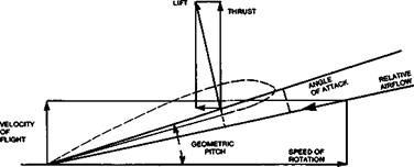
NOTE: IN OLD TEXTBOOKS, THE DIFFERENCE BETWEEN THE RELATIVE AIRFLOW AND THE ANGLE OF THE BLADE WAS REFERRED TO AS ‘SLIP’. IT IS ACTUALLY THE ANGLE OF ATTACK |
of the designer who must nonetheless produce a propeller which will not fly apart under the considerable stresses caused by high rotational speeds, and will distort as little as possible under the air loads.