Our heavyweight helicopter equal in the world does not have
In Rostov started production of the most load-lifting rotary-wing car The Russian holding «Helicopt[...]

Everything about aircrafts and helicopters. News and events in aviation worldwide. Civil, transportation, military helicopters and airplanes.

Everything about aircrafts and helicopters. News and events in aviation worldwide. Civil, transportation, military helicopters and airplanes.

Everything about aircrafts and helicopters. News and events in aviation worldwide. Civil, transportation, military helicopters and airplanes.

Everything about aircrafts and helicopters. News and events in aviation worldwide. Civil, transportation, military helicopters and airplanes.


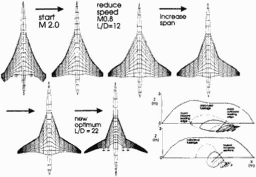
To illustrate the working of the optimizer we decided to change the Mach number from M 2.0 to 0.8 and make the wing span a design variable. In addition the length of the nacelles was halved to simulate a current high bypass ratio turbofan. We took the supersonic aircraft of the previous section and analyzed it at the subsonic speed of Mach 0 8. Though its lift-to-drag ratio improved to 12 because of the absence of wave drag, this was clearly not an optimal configuration at this flight condition. Figure 95 shows what happened Immediately after the start of the optimization, the span is increased to the maximum allowable span of 60 m ю reduce induced drag. Ncxi the wing area is reduced to reduce friction drag After about 12 hours, the configuration had converged K> the last shape shown which had a lift-to-drag ratio of 22, slightly belter than current transonic aircraft. The fact that the aircraft looks a bit like a VariEzc probably stems from the fact that the landing gear is still stored in the w ing and the aircraft has the cimc neutral point and pitching moment as the original BSCT. The outboard wing sweep looks fairly realistic. Local maximum wing normal Mach numbers are around 1.15. a very reasonable value for cruise flight, and perhaps a bit unexpected considering that we are running a panel code. Limitations to the leading edge suction and pressure levels as implemented in the potential flow code could he responsible for this phenomena Area ruling is taken out and the minimum fuselage dimensions arc selected Notable is also the automatic rcpanncling of the wing-body interface with the wing root blended into the fuselage. If we look at the section design, we notice that wing looks like a transonic aircraft design: wash out twist, large leading edge radius, and rear loading.
|
Figure 95 ESCT morphed into a VariEze type subsonic transport |
Since shocks are not modeled here, and since the design constraints arc not typical for a subsonic transport, one should not attach to much meaning to this morphed ESCT design. However. the results clearly show the flexibility of this method.
16.6 Conclusion
In this paper we present a general method for aerodynamic shape design, based on direct numerical optimization of aero-shape functions. The method was applied to the design of a 3D supersonic wing body configuration. This method is computationally efficient and competitive with designs obtained using current industnal methods, resulting in overall organizational time savings of approximately a factor of three and producing designs of comparable to better quality than those produced by inverse methods.
Acknowledgements
I would like to thank Ralph Carmichael of NASA Ames for his earlier help with the w mgbody code, and my colleagues at Stanford University: Prof. Han Kroo. Peter Gage and Scan Wakayama, who helped me with my initial attempts to use optimization Much of this work would not have been possible without the programming assistance of Siikc Logcmann. I would also like to thank Dr. M. Yoda for her editing of this paper Finally, I would like to thank Dr. Mertens of Daimler Benz Aerospace Airbus for his organizational and personal support.