Interferometry
Two beams interferometry is based on the comparison between the optical paths of pairs of light rays that pass through a test field in which the index of refraction, n, is not homogenous. The optical path traversed by a light ray is defined as the curvilinear integral
I = J n(x, y,z)ds (6.11)
where ds is an element along the path and n(x, y, z) is the distribution of the index of refraction in the test field. (In a vacuum, where n = 1, the optical path coincides with the geometrical path.) Pairs of coherent light rays that travel different optical paths can create interference, in particular, negative interference, a black point, if the difference between the optical path of the two rays is equal to an odd number of half wavelengths, see Equation (4.7):
M = ± (2^+ 1)j [n = 0, 1, 2……… ] (6.12)
and positive interference in a point, where the brightness is equal to four times the brightness of the single rays, see Equation (4.7), if the optical path difference is equal to an even number of half wavelengths (a multiple of wavelengths):
![]() M = +2N— = ±N—
M = +2N— = ±N—
2
In the image of the test chamber, a pattern of stripes, interference fringes, is generated. This phenomenon occurs only if the two interfering beams are generated by coherent sources (i. e. sources that emit light waves with the same wavelength and constant phase difference). Because it is impossible to obtain two distinct and perfectly coherent sources, it is necessary to use a single source and split the beam into two beams which are then recombined.
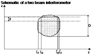
In order to introduce a classification of different systems it can be assumed that all light rays are straight and parallel to the axis z. Assume that the pairs of conjugate rays lie in the plane x, z (Figure 6.26) and that in the test field are separated by the distance d. If the coordinates of the two input rays in the test field are indicated by Z and Z2, and the coordinates of output with Z and Z2, the difference in optical pathlengths of the two rays is given by:
 (6.14)
Unfortunately from this equation it is not possible to determine n(x, y, z) since in it are two unknowns: the distribution of the refractive index
 |
Figure 6.26
along two trajectories. All systems used for optical interferometry reduce the number of these unknowns to one. One can identify two types of different devices depending on the distance between the two rays and therefore interferometers will be classified as separate beams interferometers and differentials interferometers.
If D is the diameter of the test field, when d/D > 1, one of the two conjugate rays will pass outside the test field, usually through a medium with a constant and known refractive index n = n0 . These rays form a reference beam that is made to interfere with the test beam. The difference in optical path in this case is:
where L is the size of the test chamber in the z direction. The separate beams interferometers are therefore sensitive to the absolute change in refractive index or density. The typical instrument of this class is the Mach-Zehnder interferometer.
Differential interferometers are characterized by a very small ratio between the separation of the rays and the diameter of the test field, d/D << 1: in practice, both the two conjugate rays pass through the test field, separated by an infinitesimal distance d. These interferometers are also called Schlieren interferometers because the optical apparatus is very similar to the Schlieren system.
Developing Equation (6.14) in a Taylor series truncated at the linear terms, since d is infinitesimal, we have:
similar to Equation (6.10) for n = 1.
Many differential interferometers have been made, some of them can only operate using a laser as a light source, the most commonly used is the Wollaston prism interferometer.
There are many advantages using differential interferometers with respect to separated beam interferometers:
■ separated beams interferometers cannot be used whenever the difference in optical paths between the two beams is higher than the coherence length (the presence of thick glass windows in one of two paths);
■ in a differential interferometer, since both the interfering rays pass in the test chamber separated by an infinitesimal distance, they are equally affected by any vibration;
■ differential interferometers do not require the elaborate and sophisticated alignment procedures needed in separated beams interferometers;
■ differential interferometers can be made in large dimensions because the mirrors used, which are the same of the Schlieren system, easily reach a diameter of 50 cm, with costs much lower than those of the high quality optical components of a Mach-Zehnder interferometer;
■ the cost of a differential interferometer is extremely low because the optical components of the Schlieren equipment are usually already available in any fluid dynamics laboratory.


