Our heavyweight helicopter equal in the world does not have
In Rostov started production of the most load-lifting rotary-wing car The Russian holding «Helicopt[...]

Everything about aircrafts and helicopters. News and events in aviation worldwide. Civil, transportation, military helicopters and airplanes.

Everything about aircrafts and helicopters. News and events in aviation worldwide. Civil, transportation, military helicopters and airplanes.

Everything about aircrafts and helicopters. News and events in aviation worldwide. Civil, transportation, military helicopters and airplanes.

Everything about aircrafts and helicopters. News and events in aviation worldwide. Civil, transportation, military helicopters and airplanes.


Any apparatus that produces images in which the brightness depends on the local deviations that light rays undergo when crossing the test zone is generally classified as Schlieren. Strictly speaking, the shadowgraph is also a Schlieren, but currently this name is attributed solely to the method proposed by Toepler in 1866.
In this system (Figure 6.20), a first lens produces a beam of parallel light rays passing through the test chamber, a second lens produces an image of the test chamber on a screen and an image of the light source in its focal plane. A knife edge or cut-off is introduced into the focus, to cut a fraction of the image of the source.
To understand how the system works, it should be noted that the light source is of finite size, usually rectangular 10 mm x 1 mm (Figure 6.21,
![Подпись: of flow facility Source: [4]](/img/3131/image337_0.gif) |
bottom left). Each point of the source (Figure 6.21) produces a pencil of parallel rays passing through the entire test chamber and is focused in a point; the focus consists of the focal points of all the pencils that have crossed the test chamber, bearing with them all the information. In the absence of disturbances in the test chamber, cutting part of the focus with a knife edge only makes the light on the screen reduced, without any loss of part of the image of the test chamber on the screen. The loss in brightness is proportional to the fraction of the image of the light source cut by the knife edge, (b – a)/b, where b is the height of the light source and a is the height of the part of it not intercepted by the knife edge (Figure 6.22b). Usually the knife cuts half of the focus (a = b/2).
On the other hand, every ray that passes through the test chamber is the sum of rays coming from all the points of the source and focuses on all the points of the image of the source, and for this reason the image of
 |
Pencil of rays generated from various points of a light source of finite size. In detail at the bottom left the system used to generate a rectangular source
 |
Source: [5]
the source can be thought of as the overlapping of all the images produced by all the rays passing through the test chamber.
If there is a density gradient in the test chamber, the ray passing through that point is deflected either upwards or downwards depending on the sign of the density gradient, and the corresponding image of the source moves by ±Da with respect to the knife edge and then is cut more or less than other images of the source formed by the undisturbed rays (Figure 6.22b). This shift and the resulting change of lighting of the corresponding point on the screen are proportional to the deflection angle.
Assuming that Qx is small, from Figure 6.22a is obtained that:
Da(x, y) = /2tan0x(x, y) = fAU, y) (6.9)
When Da(x, y)/a = ±1, the maximum deviation angles, Qxmax, is reached, beyond which no further changes occur in brightness (saturation o/ Schlieren) because the source images are either completely cut by the knife or not cut at all.
![]()
The contrast at the point (x, y) of the image is given, for Equation (6.6) and Equation (6.9), by
![]() Al(x, y) Aa(x, y)
Al(x, y) Aa(x, y)
a
![]() dlnn(x, y)dz_ вх (x, y) dx #
dlnn(x, y)dz_ вх (x, y) dx #
The sensitivity, s, defined as the relative deflection, Aa(x, y)/a, obtained at the knife for the unit deflection of the ray in the test chamber
a 0X (x, y) ex
increases with the focal distance of the second lens. To increase the sensitivity, the value of b = 2a can also be reduced, but this means a decrease in global brightness. An excessive sensitivity may otherwise not be desirable because even the small gradients of density present in the laboratory are magnified, thereby introducing a noise in the image.
Note that the Schlieren system is only sensible to the component Aa(x, y) of the displacement normal to the knife edge (Figure 6.22b); since this shift is a function of the gradient of the refractive index in this direction, the knife must be oriented appropriately depending on the phenomenon to be visualized (normal shock wave, oblique shock wave, boundary layer, etc.). Although a rectangular source and a straight-edged knife are commonly used, rarely for particular applications can other shapes be used, for example, a circular source and a ring knife can be used if a uniform sensitivity in all directions is required. Usually on the photos obtained with the Schlieren system are reported the type and orientation of the used knife edge to make easier the interpretation of the image (Figure 6.23).
In Figure 6.24, the Schlieren images for different operating conditions of a de Laval nozzle are shown.
Since the eye is more sensitive to changes in color than in brightness, it is preferable to use Schlieren configurations that obtain color images in which every nuance of color corresponds to a particular density gradient in the flow. One approach is easily achievable replacing the knife with some transparent and colored parallel stripes, made of sheets of cellulose acetate or gelatin filters. No more than three colors are generally used and the three-color filter is positioned parallel to the light slit. The combination red-yellow-blue gives the better contrast: the undisturbed
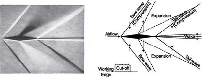
Schlieren photograph of a double wedge in a flow at M = 1.6 and its interpretation
|
|
field is yellow, the gradients deflecting the rays in a direction give red zones and those deviating them in the opposite direction give blue zones.
Using Equation (6.10) quantitative results from a Schlieren could be obtained using a photodensitometer on the photographic negative. Quantitative results could also be obtained by doing a direct scan of the focal plane of the Schlieren system with a photomultiplier. In practice, significant difficulties arise in the accurate photometric analysis of the image, and also for the aforementioned problem of saturation: this can be avoided only if the knife is replaced by a gradual filter with various shades of gray. Once again, the filter should be placed so that the direction of change of gray is in the same direction of the density gradient to be measured.
The Schlieren system is usually not used to get the value of density, but is extremely useful in the qualitative description of the test field.
For the large diameters (D > 100 mm) required to illuminate the windows of a supersonic wind tunnel, lenses are usually replaced with concave mirrors; in fact, a mirror is easier to build and less expensive than a lens because:
■ the internal quality of the glass is not important;
■ it is necessary to work on only one surface;
■ a mirror absorbs less light than a lens;
■ chromatic aberration is eliminated.
Mirrors with a protecting glass, like those for home use, cannot be used since a double reflection is produced, the first on the covering glass and the second on the mirror surface. The reflecting surface must therefore be exposed to the air: aluminum is usually used, because its oxide (Al2O3) is transparent.
![]()

![Подпись: Source: [6]](/img/3131/image348_1.gif) |
Schlieren images of flow in a supersonic nozzle at different ambient pressures
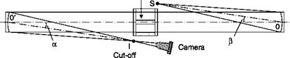
When using mirrors, the source and the knife should be placed outside the optical axis (Figure 6.25) the mirrors should be in the form of an offset paraboloid. The production of mirrors of this type, however, is
Z-configuration of a Schlieren system with mirrors
|
Model Linder Test (Flow normal to Plane of Paper) Source
|
expensive and spherical mirrors are preferred; this approximation is allowed if the ratio between focal length and diameter of the mirror is more than 10.
To minimize the aberrations due to a spherical mirror, the offset angles a and b of Figure 6.25 must be small and also of opposite sign so that the source and the knife are on opposite sides of the axis of the two mirrors. The first precaution minimizes the effects of astigmatism, the second, the effects of coma. It is also necessary that the astigmatism distorts the image only in the direction parallel to the edge of the knife; this may be done by placing the source, the knife and the optical axis of the system in the same plane.