Our heavyweight helicopter equal in the world does not have
In Rostov started production of the most load-lifting rotary-wing car The Russian holding «Helicopt[...]

Everything about aircrafts and helicopters. News and events in aviation worldwide. Civil, transportation, military helicopters and airplanes.

Everything about aircrafts and helicopters. News and events in aviation worldwide. Civil, transportation, military helicopters and airplanes.

Everything about aircrafts and helicopters. News and events in aviation worldwide. Civil, transportation, military helicopters and airplanes.

Everything about aircrafts and helicopters. News and events in aviation worldwide. Civil, transportation, military helicopters and airplanes.


In most of this book, the modelling of the extreme ground effect implies that the ground clearance is much less than the chord and the span. This type of ground effect, associated with pronounced stagnation under the wing, will be designated as chord dominated ground effect (CDGE).[64] On the other hand, when considering the aerodynamics of a wing of large aspect ratio in the extreme ground effect on the basis of lifting line theory, it was assumed that the chord is much less than the ground clearance, the latter being much smaller than the span. In this case, we can introduce the notion of a span dominated ground effect (SDGE). Although both of these effects imply an increase in the lift-to drag ratio at smaller ground clearances, it can be shown that they have somewhat different natures. To distinguish this difference, compare the behavior of the lift and the induced drag coefficients of a wing of large aspect ratio versus the ground clearance within the previously mentioned models. In the calculated examples, the relative span and angle of pitch of the wing were l = 8 and в = 0.05, respectively. In the CDGE, calculations of of lift and the induced drag coefficients were made for cases of rectangular and (optimal) semielliptic flat wings by using formulas (3.65), (3.67), (3.78), and (3.80). The aerodynamic coefficients, corresponding to the SDGE, were determined by formulas (10.27), (10.29), (10.32), and (10.35), corresponding to rectangular and (optimal) parabolic planforms.[65]
Figure 10.2 shows that for a fixed pitch angle with a decrease in the relative ground clearance (based on the chord), the CDGE model responds by an increase of both the lift and the induced drag coefficients. As seen from formulas (3.65), (3.67), (3.78), and (3.80), both coefficients within the CDGE model are inversely proportional to the ground clearance. Note that Standingford and Tuck[101] came to the same conclusion in their accurate numerical analysis of the aerodynamics of lifting surfaces for small ratios of the ground clearance to the chord.
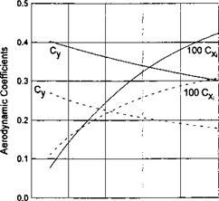
As seen from Fig. 10.3, the behavior of lift and induced drag coefficients versus the relative ground clearance (based on span) within the SDGE model is different. In this case for a fixed pitch angle we can observe a decrease in the induced drag coefficient as the wing flies closer to the ground. The lift coefficient increases with a decrease in the ground clearance although somewhat more slowly than in the CDGE model.[66]
![]()
 |
|
 |
|
|
|
|
|
![]()
|
In these equations 2(z) stand for the distributions of the loading in the direction of the span of the front and rear wings of the tandem, C(z) represents the form of the chord distributions, and 0 1,2(2) are the distributions of the pitch angle along the span of the wings.
It can be seen from observation of the right-hand side of equation (10.36) that in the extreme ground effect, the downwash induced by the rear wing upon the front wing is negligible. At the same time, the front wing affects the aerodynamics of the rear wing, see equation (10.37). The system admits closed form solutions.
Suppose that both wings are rectangular, C(z) = 1, and flat 0i(0) = 01,02(0) — 02* Then, the first equation of the system (10.36)-(10.37) can be integrated to yield
„ , . 27Г01 /coshpz І A I l. л
^ = “T~( coshp _1)’ P = 2ЇтК = V 2nhi ^°’ ^
Substituting solution for Г (z) in the second equation of the system (10.36)- (10.37), we obtain the following nonhomogeneous ordinary differential equation for function /2(2:):
^… ~P2 r2(z) = p + gcoshpz, (10.39)
where p = 02//ii, q = 2Qi/h coshp. Integrating (10.39) and using the requirement that the loading should vanish at the wing tips Г2(± 1) = 0, we obtain the following solution for r2(z):
 |
Using expressions (10.38) and (10.40) for the loading along the front and rear wings, we can readily obtain both the lift and the induced drag coefficients for the above case of a rectangular planform of lifting elements of the tandem.
However, in what follows, the accent will be on a parabolic loading distribution for which each of the wings and the tandem as a whole have minimal induced drag for a given lift. Writing the circulations and the planform equations of both lifting lines as A,2(2) = Г0і 2(z2 — 1 ),C1>2(^) = C(z) = k( 1 — z2),k = 3/2 and substituting these expressions into equations (10.36) and (10.37), we obtain the following simple system of algebraic equations with respect to the amplitudes of the loading distributions:
wherefrom
The lift coefficients of each wing and the overall lift coefficient of the tandem C* are obtained in the form
![]() 4/.Г10 8ir9i
4/.Г10 8ir9i
~ 3 = 3(1 + 4nh/l)’
4ІГ20 _8n(92-3hiCyi/l) З “ З 1 + 4wh/l
cyt = cyi + СУ2.
In the latter coefficient, the reference area used was half that of the tandem. For optimal wing loading, the downwash on both lifting lines is uniform along the span:
Q? wi — 2/q. Ao, t^w2 — 2/11A20 H – 4/ii-Ao* (10.46)
Consequently, the induced drag coefficients for the front and rear wings can be found in the form
![]() The induced drag of the tandem as a whole[67] will be
The induced drag of the tandem as a whole[67] will be
Cx = CX1 + CX2 = ~2[(Су! + 2СУіСУ2 + Cy2) = + СУ2)2. (10.48)
It is worthwhile to remember here that an optimal tandem in an unbounded fluid (h = oo) has the following relationship between the lift and the induced drag coefficients of its elements:
CXl + CX2 — (Cyi + Cy2)2. (10.49)