
Our heavyweight helicopter equal in the world does not have
In Rostov started production of the most load-lifting rotary-wing car The Russian holding «Helicopt[...]

Everything about aircrafts and helicopters. News and events in aviation worldwide. Civil, transportation, military helicopters and airplanes.

Everything about aircrafts and helicopters. News and events in aviation worldwide. Civil, transportation, military helicopters and airplanes.

Everything about aircrafts and helicopters. News and events in aviation worldwide. Civil, transportation, military helicopters and airplanes.

Everything about aircrafts and helicopters. News and events in aviation worldwide. Civil, transportation, military helicopters and airplanes.


In the preceding paragraph the assumptions of monochromatic and point light source were made. The basic requirement, in order to ensure that the two intersecting beams give interference, is that the phase difference of rays remains constant in all the observation time. This is linked to conditions on the spectral amplitude of the light emitted (temporal coherence) and the finite extension of the source (spatial coherence).
Consider the extreme case of only two sources whose wavelengths differ by D1: the system of fringes disappears when the Nth bright fringe produced by the light with wavelength 1 falls on a dark fringe produced by the wavelength 1 + D1. The difference in amplitude of the fringes is, for Equation (6.19) Dw = D1/2e and the condition of cancellation of the fringes is:
![]() ,,, w Л7 Я
,,, w Л7 Я
NDw = — ^ N =————-
2 2АЛ
then with a given 1 and a given amplitude of the spectrum of the source, the equation allows calculation of the maximum number of fringes that can be obtained: for red light (1 = 632.8 nm) and an interferometric filter with bandwidth, D1 = 1 nm, about 300 fringes can be generated.
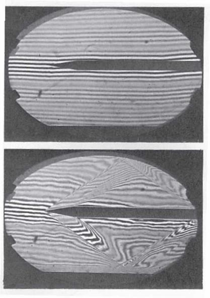
With a white light fringe, this phenomenon clears all except the white fringe of zero order and a few colored fringes on each side of it (Figure 6.32, top). This particular feature is used to follow the fringe shift through a shock wave: with the white light it is very easy to follow the brightest zero-order fringe (Figure 6.32, bottom).
A finite source may be regarded as consisting of many source points, so in every point on the screen the light intensity is the result of some interfering pairs rather than a single pair. The interference is obtained only if the difference in optical path between a pair of ray changes by no more than 1/2 on the whole source.
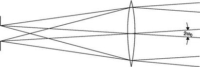
From Figure 6.33, we can see that there are a number of beams of parallel rays from each point of the source entering the interferometer; between the two extremes there is an angle of 2w0. If the central beam enters the interferometer at 45° from the surface of the first beam-splitter and if the produced fringes are perpendicular to the plane of the centers, from simple geometric considerations it can be found that the maximum number of fringes in the field is:
|
|
|
|
|
|
|
It is also difficult to obtain good contrast of the fringes in the presence of dispersion in the various optical components. The limited spatial and temporal coherence of the normal light source, usually mercury arc lamps filtered with a narrow band interferometric filter (AX = 1 nm), implies the need for strictly equal path lengths which limits the tolerance in the initial assessment of the instrument to a few wavelengths. If the test chamber has windows, these introduce an optical path difference between the test and reference beams of the order of a few centimeters and it is therefore necessary to make the two path lengths equal, introducing into the reference path a pair of glasses identical to the windows of the test chamber (the compensation chamber, CC, of Figure 6.27) or by passing also the reference beam through the test chamber in an area where the density is constant and is known.
In practice, the Mach-Zehnder interferometer requires five adjustments and high quality precision optics: all optical surfaces, including the windows in the test chamber, must be machined with great precision, so that the thickness of the mirrors must be constant within a tolerance of less than X/12. This type of interferometer requires adequate structural rigidity and must operate in the absence of vibrations that could alter the optical path difference between the two beams.
Using a gas laser, which acts as an ideal point source for monochromatic and coherent light, the coherence length is of a few decimeters (see Chapter 4) and most of these difficulties disappear. The use of a laser has the following effects:
■ tolerance in the initial set-up of the interferometer is of some decimeters;
■ there is no need to make equal the thickness of the optical components
in the two paths;
■ a large number of well-contrasted fringes is easily obtained;
■ three of the five fine adjustments of the interferometer become
redundant, there remain only the controls on spacing and inclination of the fringes.
Unfortunately, the coherence of laser light introduces new difficulties:
■ the rear surface of the beam splitters and each surface of the windows of the test section reflect light in the direction of the main beams: since this light is coherent with that of the main beams, spurious fringes are generated that may also have a high contrast; this phenomenon can be eliminated by treating the concerned areas with an anti-reflective coating (e. g. MgFl2 reflecting only 4% of incident light);
■ laser light is diffracted on each object placed in the beam out of focus, including dust particles and fingerprints on lenses and mirrors: diffracted light is coherent and produces other spurious fringes; this requires an extreme and continuous cleaning of the optics surfaces. The problem is greatly alleviated if the laser beam is passed through a spatial filter (see Section 4.2.5).


