
Our heavyweight helicopter equal in the world does not have
In Rostov started production of the most load-lifting rotary-wing car The Russian holding «Helicopt[...]

Everything about aircrafts and helicopters. News and events in aviation worldwide. Civil, transportation, military helicopters and airplanes.

Everything about aircrafts and helicopters. News and events in aviation worldwide. Civil, transportation, military helicopters and airplanes.

Everything about aircrafts and helicopters. News and events in aviation worldwide. Civil, transportation, military helicopters and airplanes.

Everything about aircrafts and helicopters. News and events in aviation worldwide. Civil, transportation, military helicopters and airplanes.


The simplest differential interferometer [10] consists of a glass plate on which the rays reflected from the first and the second surface of the plate are made to interfere. The plate can be put immediately after the test chamber before the second mirror of the Schlieren system. In this case, a beam of parallel rays hits the plate (Figure 6.41): ray 1 is reflected in part on the upper surface of the plate (ray 1′) and partly propagates within it undergoing a refraction in passing from air to glass. The ray refracted, in turn, partly passes into the air and is in part reflected by the lower surface and refracted through the upper surface (ray 1"). Among all the rays that reach the plate, there is a ray 2 that produces a reflected
 |
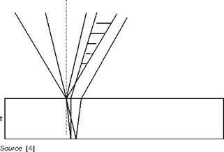
Schlieren interferogram of a shock wave with vertical or oblique fringes
![Подпись: Source: [4]](/img/3131/image375_2.gif) |
Exact position ^ of shock wave
ray 2′, overlapping 1" and giving rise to interference. Similarly, there is a radius 3 that generates a ray 3′ interfering with the ray 2", and so on. The difference in optical path between interfering rays is equal for all rays and is given by the geometric path of the refracted ray in the slab, multiplied
 |
Figure 6.41
by the refractive index of glass, nv, minus the path in air of the ray reflected from the upper surface, multiplied by the refractive index of air, na.
With simple geometrical considerations it is easy to write
M = 2tt]n2r – n2a sin2 i (6.23)
where t is the thickness of the slab and i is the angle of incidence of the beam on the plate.
If the beam has passed through an object with a constant density, interference fringes are not formed and the uniform brightness of the beam downstream of the plate (no fringes) depends on the optical path difference given by Equation (6.23). If the density of the test field is variable, interference fringes are formed that are loci of equal density gradient.
Separation distance between the interfering rays is given by
![]() tna sin2i
tna sin2i
![]() 2 • 2 •
2 • 2 •
nv – na sin i
In fact, in this type of interferometer, rays that interfere are more than two because there are multiple reflections inside the slab, for example, there will be a radius 1’" which also interferes with the radius 3′, but successive reflections decrease in intensity and thus contribute more and more negligibly to the phenomenon of interference. Apart from the inability to generate finite width fringes, this type of interferometer is limited due to the fact that a plate of interferometric quality, which is therefore expensive, is needed.
These constraints can be removed if the plate is in the focus of the Schlieren system replacing the knife edge. The cone of light reflected from the first face of the plate interferes with the one refracted and then reflected from the second surface of the plate (Figure 6.42). The area of the plate affected by the cone of light is the order of mm2 and therefore the quality of the slab is virtually irrelevant.
 |
||
Since the single rays have different incidence on the plate, the optical paths are different from ray to ray, so even in the case of a uniform field, fringes will be present (finite width fringes), the width of which is at a first approximation inversely proportional to the thickness of the slab. The distance of separation of the rays that interfere at a distance D from the focus is given by:

 |
Reflection plate interferometer in the focus of a Schlieren system
Separation varies with the angle of incidence and therefore the sensitivity varies from point to point in the test section. The thickness of the fringes is given approximately by:
The choice of the angle of incidence is dictated by the need to have fringes as far as possible straight, parallel and of uniform thickness. Since the reflected rays from the first and second face of the slab can be considered as coming from two point sources, the surfaces of interference, constructive or destructive, are hyperboloids of revolution (Young’s experience) that are the loci of points which have a constant geometric path difference between the two coherent sources in phase with each other (Figure 6.43).
It is obvious that the shape of the fringes depends on the position of the observer with respect to the line joining the two light sources (axis of revolution of the hyperboloid): circular, elliptic or hyperbolic fringes can be observed with increasing angles between the direction of observation and the axis of revolution.
In Figure 6.44 are shown fringes obtained at different angles of incidence with three plates of different thickness. With all the plates fairly straight and parallel, fringes are obtained with angles around 45°. At small angles of incidence, fringes are curved; at too large angles of incidence, the phenomenon of multiple reflections will take place with a
 |
Standing waves produced by two sources in phase; on right, equal phase surfaces (hyperboloids)
loss of sharpness of the fringes. Few fringes are generated by the thinner slide (t = 0.15 mm) and fringes too numerous and almost indistinguishable with the thickest one (t = 1.60 mm).


