
Our heavyweight helicopter equal in the world does not have
In Rostov started production of the most load-lifting rotary-wing car The Russian holding «Helicopt[...]

Everything about aircrafts and helicopters. News and events in aviation worldwide. Civil, transportation, military helicopters and airplanes.

Everything about aircrafts and helicopters. News and events in aviation worldwide. Civil, transportation, military helicopters and airplanes.

Everything about aircrafts and helicopters. News and events in aviation worldwide. Civil, transportation, military helicopters and airplanes.

Everything about aircrafts and helicopters. News and events in aviation worldwide. Civil, transportation, military helicopters and airplanes.


As discussed earlier, there are few studies of the aerodynamics of flapping wings associated with anisotropic wing structure; in addition, the 3D wing shape and the timing of deformation during flapping flight have not yet been studied well. Recently, Nakata and Liu [523] conducted a computational analysis of hawkmoth hovering flight based on a realistic wing-body model, which takes into account the anisotropy of a hawkmoth wing. They investigated how the wing deformation and modified kinematics due to the inherent structural flexibility affect unsteady fluid physics and aerodynamic performance. In their study, a reasonably representative wing – body morphological model was built as shown in Figure 4.54. Note that although hawkmoths are four-winged, for simplicity, they modeled the fore – and hindwings as a single pair of wings because of the highly synchronized motion observed in flapping flight. Hawkmoths’ wing structure is mainly supported by wing veins and membrane. The wing veins are clustered and thickened around the wing base and leading edge, as illustrated in Figure 4.54a, and are tapered toward the wingtip and trailing edge [403] [524]. A thin flexible membrane is placed between the veins; the directional arrangement of the wing veins and the difference of bending stiffness between the veins and membrane result in a high anisotropy of the flexural stiffness of hawkmoth wings [402]. Wing and body kinematic models were constructed based
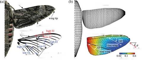 El: flexural stiffness

structural anisotropy
Figure 4.54. (a): A hawkmoth Agrius Convolvuli with a generalized wing venation including fore – and hind-wings. (b) A computational model for CFD and CSD analysis. From Nakata and Liu [523].
on the experimental data of the hovering hawkmoth, Manduca, and on kinematic parameters [247] [523] described in Section 3.7. Note that the body was assumed to be stationary because the body motion in hovering flight is negligibly small [226].
2.6.1.1 In-Flight Deformation of a Hawkmoth’s Wing
Figure 4.55 shows the comparison of the instantaneous and time-averaged results associated with flexible and rigid wings. Figure 4.56 displays the time-varying wing shape and deformation in terms of the spanwise bending, the twist, and the camber. From Figure 4.55a the flexible wing shows an advanced phase in the feathering angle, but a delayed phase in the positional angle at the wingtip, with respect to prescribed motion of the rigid wing at the wingtip. Also from Figure 4.55b, the translational and rotational velocities in the cross-section of 0.8R increase remarkably, in particular before stroke reversal. Those results occur because of large spanwise bending and twisting when the wing translates and because of small peaks before the subsequent stroke reversal as illustrated in Figure 4.56. Furthermore, although the spanwise bending and the twist angle vary smoothly, there exists a rapid increase in distal area. The flexible wings show pronounced deformation in spanwise bending and twist immediately after stroke reversal. The maximum of nose-down twist in the distal area (forewing) is approximately 12° when predicted by computation and 15° ~ 20° when measured by experimentally [226]. One can see some positive camber, less than 2 percent, that is relatively small compared with the measured cambers of large insects such as locusts [525]. Overall, such deformation leads to significant changes in wingtip kinematics.


