Our heavyweight helicopter equal in the world does not have
In Rostov started production of the most load-lifting rotary-wing car The Russian holding «Helicopt[...]

Everything about aircrafts and helicopters. News and events in aviation worldwide. Civil, transportation, military helicopters and airplanes.

Everything about aircrafts and helicopters. News and events in aviation worldwide. Civil, transportation, military helicopters and airplanes.

Everything about aircrafts and helicopters. News and events in aviation worldwide. Civil, transportation, military helicopters and airplanes.

Everything about aircrafts and helicopters. News and events in aviation worldwide. Civil, transportation, military helicopters and airplanes.


Lift
It is easier to understand the concept of aircraft lift with Newton’s laws rather than Bernoulli. The Bernoulli principle/approach is the one that is generally used to describe lift [4]. This explanation focuses on the shape of the wing. It does not satisfactorily explain the inverted flight and ground effect. The description of lift based on Newton’s laws can explain power curve, high-speed stalls, and ground effect. It is conventionally believed and explained that the wing produces the lift due to the fact that air travels faster over the top of the wing, which creates a lower pressure than the bottom of the wing, and this differential pressure produces the upward lift. It is not clear here why the air moves faster on the top. According to Newton’s laws, the wing changes air’s momentum, which generates the force on the wing. Thus, the wing continuously diverts lot of air downwards. Thus, the lift of a wing is directly proportional to the quantity of the air diverted down and the downward speed of the mass of air. This downward velocity is called ‘‘downwash.’’ As the wing moves along, the air is diverted down at the rear and the air is pulled up at the leading edge resulting in ‘‘upwash.’’ This combination of upwash and
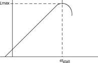
downwash, in general, contributes to the overall lift. Thus, as the air is bent around the top, it is pulled from above and this pulling causes the pressure to become lower above the wing. The acceleration of the air above the wing in the downward direction is responsible for giving the wing lift. The air is moving up at the leading edge, and at the trailing edge it is diverted downward, with the top air accelerating towards the trailing edge. The air being fluid, when it is moving and comes into contact with a curved surface it will try to follow that surface. This is known as the Coanda effect. Here, Newton’s two laws are useful: for the air (any fluid) to bend there must be a force acting on it, and the air must put an equal and opposite force on the wing surface that caused it to bend. The air follows a curved path due to its viscosity, which is a property of any fluid—the resistance to flow, a property of stickiness of the fluid. The relative velocity of the air molecules nearest to the surface (with respect to the surface) is zero, and it progressively increases as we move away from the surface. Since the air near the surface has a change in velocity, the air flow is bent towards the surface. The volume of the air around the wing seems attached to the surface and this phenomenon is known as the boundary layer. Effectively the wing is forcing the air down, or pulling the air downward from above. The wing that produces the lift would be at a certain angle of attack (AOA) that determines the lift (Figure A4). The AOA is adjusted to get a certain lift for the speed and the load. The lift begins to decrease at a certain AOA; it could be 12°-15°. The force necessary to bend the air to such a steep angle is much greater than could be supported by the viscosity of the air. This is the cause of the separation of the air from the wing and leads to the stall of the wing, the reduction/loss of the lift.
We have seen that the lift of the wing is proportional to the amount of the air diverted down times the downward velocity of that air. As the aircraft’s speed increases more air is diverted. The AOA is reduced to maintain a constant lift. At higher altitudes the air density is lesser and lesser, and hence the air diverted for the same speed is less. This requires an increase in AOA. The air is left in motion after the aircraft passes ahead, the still air ends up with a downward velocity, and thus the air is infused with energy. The lift thus requires power (being supplied by the engine or by gravity). This power is proportional to the amount of air diverted down times the square of the velocity of the diverted air. We know that the lift of the wing is proportional to the amount of the air downward times the downward velocity of the air. Hence, the power required to lift the aircraft is proportional to the load (weight)
|
|
times the vertical velocity of the air. If the aircraft speed is doubled, the amount of air diverted doubles. The AOA should be decreased to reduce the vertical velocity to half for the same lift. Thus, the power required for the lift has been reduced to half. The power to create lift is, in fact, inversely proportional to the speed of the aircraft.
The amount of air in the downwash also changes along the wing. The downwash comes off the wing in the form of a sheet. The wing at the root diverts more air (than at the tip), the net effect is that the downwash sheet begins to curl outward around itself, producing the wing vortex, tightness of the curling of the vortex being proportional to the rate of change in the lift along the wing. At the wing tip the lift is nearly zero, and the tip vortex is tightest.
Near the ground the upwash is reduced due to the fact that the ground reduces the circulation of air under the wing, requiring reduced downwash of the air (to provide the lift). The AOA is reduced and hence the induced power. This makes the wing more efficient due to the ground effect. Thus, the ground effect, the improved efficiency of the wing, is more correctly explained rather than as the result of the air compressed between the wing and the ground.
Drag
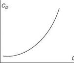
Drag is the force experienced by an aircraft moving forward with TAS V. It is a retarding force that acts parallel to and in the direction opposite to V. Mathematically, it is expressed as
D = CoqS (A.21)
where CD is the drag coefficient (Figure A5), q is the dynamic pressure, and S is the reference wing area. The total drag coefficient at subsonic speeds is given by
CD = CDp + CD;
where CD is the profile drag, which is made up of skin friction drag and the pressure drag due to separation. CD is the induced drag coefficient, which varies as the square of lift coefficient and is given by
C2
 |
CDi=pAe
where A denotes the wing aspect ratio (AR) and e is the span efficiency factor, which generally varies from 0.8 to 0.95. The drag coefficient is also expressed in the form
c2
Cd = CDa + — (A. 22)
pAe
where CD is the zero lift drag coefficient. In addition to these drag components, another component is the wave drag, which occurs at supersonic flows and is the result of the pressure increase across the shock wave. Wave drag can be minimized by keeping the supersonic airfoils thin with sharp leading edges.