Calculation of the profile drag by measuring the pressure in the wake of the model
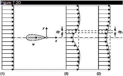
The profile drag of a body can be found by measuring the deficit of momentum that occurs in the wake. Consider (Figure 7.20) an airfoil immersed in a stream and apply the equation of balance of momentum in the direction of the stream between a section (1) infinitely upstream of the body, where the velocity and pressure are those of the undisturbed flow, and a downstream section (2) where velocity and pressure are variable in the wake. Denoting by u the unit tensor and by i the versor of the x axis:
E (p.’P. Ui dy-
■L (p+ ,}Ul)2 d’-iS(pH + T*l’)idS = 0 C.12)
 |
Determination of profile drag with the Jones method
U,.
The third integral represents the profile drag, Dp, sum of the form (or wake) drag generated by normal stresses and of the friction drag generated by the viscous stress tensor, tm. Therefore, the profile drag, Dp, can be calculated from the equation”
«««Л (-+p-1>1 – Л ( +p 2)2 (7Л3)
Integrals of Equation (7.13) must be extended from – да to +да as for the conservation of mass is:
П(pU)i dy = J~(pU) dy (7.14)
which shows that the velocity outside the wake at the station (2) must be greater than ида in order to compensate for the flow deficit that occurs in the wake.
Taking account of Equation (7.14), Equation (7.13) can be written:
Dp = Л ( – p)y + Л P2U2 ( – U2)dy (7.15)
Since the test chamber has a finite size it is necessary to use some approximations to measure the drag profile. Of all the methods devised to calculate the drag from the balance of momentum, the most commonly used is that of Jones. This method allows the calculation of drag from measurements made only in the wake with an error < 2%.
In an incompressible flow, assuming that the pressure in the station (2) is equal to the pressure of the undisturbed stream, рда, i. e. that station (2) is chosen at a very large distance downstream of the airfoil and that outside the wake of the velocity U ~ ида, the integral can be extended only to the wake (from – yw to yw):
Dp =jy PU2 (U.-U )y (7.16)
Since the test chamber has a limited length, a control station (3) not far from the airfoil (e. g. after 2 – r – 3 chords) must be used. Assuming that between the stations (2) and (3) the Bernoulli theorem is valid (no turbulence in the wake):
U1 U2
![]()
![]() P03 = Рз + PЧ3 = P – + P~2
P03 = Рз + PЧ3 = P – + P~2
The equation of continuity, for incompressible flow, is:
j+/’ U3dy = j+y U2dy
It is assumed that the wake has the same size in sections (2) and (3) and that the wake is not turbulent: in these two assumptions lies the inaccuracy of the method of Jones. Equation (7.16) becomes:
Taking into account Equation (7.17), the drag coefficient is calculated from:

![]()
![]() (7.20)
(7.20)
To determine the drag coefficient using Equation (7.20) it is therefore sufficient to use Pitot tubes and static pressure tubes: the undisturbed stream conditions, p0x and pm, are measured upstream of the airfoil, the distributions of stagnation and static pressure in the wake section may be obtained with a wake-rake consisting of a series of static and Pitot tubes connected to a multitube manometer.
In the case of compressible flow Equations (7.17), (7.18), (7.19) and
(7.20) become:
(7.21)
![]()
1+У P3U3dy = J_7′ P2U2dy


