Our heavyweight helicopter equal in the world does not have
In Rostov started production of the most load-lifting rotary-wing car The Russian holding «Helicopt[...]

Everything about aircrafts and helicopters. News and events in aviation worldwide. Civil, transportation, military helicopters and airplanes.

Everything about aircrafts and helicopters. News and events in aviation worldwide. Civil, transportation, military helicopters and airplanes.

Everything about aircrafts and helicopters. News and events in aviation worldwide. Civil, transportation, military helicopters and airplanes.

Everything about aircrafts and helicopters. News and events in aviation worldwide. Civil, transportation, military helicopters and airplanes.


Gyroscopic effects arise from the propeller and rotating parts of the engine. Fortunately on models these are small, but may sometimes be responsible for unexpected behaviour. The propeller on normal models rotates anti-clockwise when viewed from the front. A turn or yaw of the model to the left rotates the gyroscopic axis of propeller and motor. The response is a force tending to raise the nose of the model. This nose up pitch causes a gyroscopic reaction to the right. This yaw or turn to the right causes a nose down pitch and as the model pitches nose down gyroscopic reaction tends to yaw it left, and a nose up pitch follows again, causing a yaw to the right. This sequence is known as precession, and if the effect is noticeable at all, which it may be with a propeller which is heavy and rotating relatively fast, the model may ‘process’ continuously under power, apparently ‘weaving’ slightly: up, to the side, down, to the other side, up, and so on. A spinning top exhibits a similar pattern, and on some early full-sized aircraft with ‘rotary’ engines, the effect was very pronounced and responsible for many accidents. In a model the ‘weaving’ caused by precession may react with torque or other more truly aerodynamic effects, to cause stability problems. The ‘P’ force of a propeller is a case in point. A change of trim to bring the model in for landing causes a yaw due to the ‘P’ effect. This produces a nose-up gyroscopic precession (see also 15.7). In a spiral climb gyroscopic forces are particularly important since the model is turning all the time in one direction, bringing about a nose up or nose down gyroscopic moment. Substitution of a lighter propeller may help the modeller in such a situation. Note, however, that in a straight climb at a constant angle, no gyroscopic reaction arises.
|
|
|
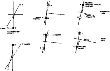
Fig. 14.18 Gyroscopic effects |
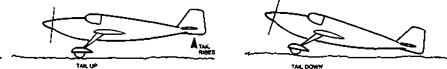
Gyroscopic reactions at take off with ‘tail dragging’ models may cause problems. As the tail wheel or skid comes off the ground, the rotating mass at the nose of the model is forced to change the direction of its axis and responds with the usual leftward rotation, causing the model to swing. A ‘ground loop’ can result. Tricycle undercarriages do not suffer in the same way (although no less affected by slipstream on the fin).
A simple explanation of the cau|e of gyroscopic reactions is given in Figure 14.18. Here an aeroplane is shown in a rapidly changing pitch motion such as during a take-off. The plane of the propeller disc is thus rotated in such a way that each blade, instead of following its usual path, is forced to follow an arc such as A-В, relative to the original disc plane. The mass of the blade resists this change and produces a strong reaction: a force appears which tries to return the blades to their original plane. On one side of the aeroplane this force acts forwards and on the other aft, so the resultant couple yaws the aircraft to one side. With the standard right-handed propellers used on models, the yaw is to the port (left) side.
The take-off phase is particularly tricky for this situation since the rudder control which must be used to counteract the yaw while the wheels are still on the ground may be relatively ineffective due to the low forward airspeed. Full rudder may be needed sometimes, if the propeller is relatively massive and if the change of attitude when the tail comes off the ground is large. Some full-sized fighter aeroplanes have proved almost uncontrollable at this moment
Many models have flown very successfully with ducted fan propulsion instead of propellers. This kind of arrangement is particularly suitable for scale models of jet aircraft Fan design is a highly specialised matter and cannot be dealt with in detail here. In theory the fan can achieve more thrust than a propeller of the same diameter, at low speeds of flight for a variety of reasons. The duct constrains the air so that all the energy from the fan is expended in accelerating the flow. The constriction of the ‘slipstream’ diameter characteristic of propellers does not occur.
The walls of the duct act as endplates to the fan blades, restraining the tip vortices and increasing their efficiency. Because the fan is of small diameter, high rotation speeds are attainable and the number of blades may be increased to create high thrust.
The disadvantages, for models, are that the engine is mounted within the duct and relies on the flow through it for cooling. This increases the drag and reduces thrust The duct walls, which, in scale models, are usually very long relative to the fan diameter, exert drag on the airstream both before and after it passes through the fan. The size of the duct opening and exit are of critical importance and it is often necessary to increase these, departing from scale outlines, in order to achieve adequate thrust Resonance of the blades can also cause trouble (an odd number of blades is necessary).
As has been demonstrated frequently, with careful design and experiment, these problems can be overcome, but there is, as yet no very precise method of designing a model fan which can be guaranteed to equal the thrust from an equivalent (though larger diameter) two bladed propeller and engine.
15