Our heavyweight helicopter equal in the world does not have
In Rostov started production of the most load-lifting rotary-wing car The Russian holding «Helicopt[...]

Everything about aircrafts and helicopters. News and events in aviation worldwide. Civil, transportation, military helicopters and airplanes.

Everything about aircrafts and helicopters. News and events in aviation worldwide. Civil, transportation, military helicopters and airplanes.

Everything about aircrafts and helicopters. News and events in aviation worldwide. Civil, transportation, military helicopters and airplanes.

Everything about aircrafts and helicopters. News and events in aviation worldwide. Civil, transportation, military helicopters and airplanes.


The universally accepted aircraft nomenclature representing the translational and rotational motions, the flow angles, and the aerodynamic forces and moments acting on the aircraft are mentioned here [1,7]. The forward edge of the wing is called the leading edge and the rear edge is called the trailing edge. The line joining the leading edge to trailing edge is called the chord. If b is the wing span and S represents the area of the wing, then the AR of the wing is given by AR — b2/S. A reference point of considerable importance is the aerodynamic center. This is the point about which there is no change in the pitching moment as the AOA is increased.
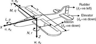
Figure A7 shows the aircraft primary control surfaces and the normally accepted sign conventions. All surface positions are angular in deflection. The elevator
|
|
|
TABLE A1 Aircraft Axes and Notations Longitudinal X-axis |
Lateral Y-axis |
Vertical Z-axis |
|
|
Velocity components |
u |
v |
w |
|
Angular rates |
Roll rate p |
Pitch rate q |
Yaw rate r |
|
Euler angles |
Roll angle f |
Pitch angle U |
Heading angle C |
|
Accelerations |
Longitudinal acceleration ax |
Lateral acceleration ay |
Vertical acceleration az |
|
Aerodynamic forces |
X |
Y |
Z |
|
Aerodynamic moments |
Rolling moment L |
Pitching moment M |
Yawing moment N |
|
Control deflections |
Elevator 8e |
Aileron da |
Rudder dr |
|
Moment of inertia |
^xx |
Iyy |
deflection causes the aircraft to pitch about the Y-axis, aileron deflection causes the aircraft to roll about the X-axis, and the rudder deflection causes it to yaw about the Z-axis. In addition to these primary control surfaces, canard is another control surface (not shown in Figure A7) found in fighters. Canard is a control surface ahead of the wing and is positioned to produce a positive lift. However, it interferes with the smooth flow over the wing and is therefore not found in every fighter aircraft. Some other control surfaces are the strakes and TEFs. Strakes are small fins placed in the horizontal plane on the aircraft forebody projecting into the airflow. This is a passive device, which increases the vortex breakdown AOA. Flaps found on the trailing edge of the wing are called TEFs. The downward deflection of these flaps causes a significant increase in lift coefficient and lift to drag ratio. The most effective range of downward deflection is from 0°-20°.
The flow angles a, b and the three Euler angles C, U, f describe the aircraft heading angle, pitch altitude, and roll angle and have already been discussed and illustrated in Chapter 3. The notations for the aircraft motion variables body-axis system are put together in Table A1 for better understanding.