
Our heavyweight helicopter equal in the world does not have
In Rostov started production of the most load-lifting rotary-wing car The Russian holding «Helicopt[...]

Everything about aircrafts and helicopters. News and events in aviation worldwide. Civil, transportation, military helicopters and airplanes.

Everything about aircrafts and helicopters. News and events in aviation worldwide. Civil, transportation, military helicopters and airplanes.

Everything about aircrafts and helicopters. News and events in aviation worldwide. Civil, transportation, military helicopters and airplanes.

Everything about aircrafts and helicopters. News and events in aviation worldwide. Civil, transportation, military helicopters and airplanes.


To ensure a numerical simulation has adequate resolution, ideally, grid refinement should be performed. Essentially, one would like to show that the computed results are grid size independent. However, for large-scale simulation this is not always feasible. Often, this is because of the complexity of the computer code. Another reason is that some simulations may require exceedingly long computer run time. This invariably discourages the performance of grid refinement. For the airfoil tone simulations, it is a medium-size simulation so that grid refinements in relation to the numerical results discussed below have been carried out. In the grid refinement exercise, all the mesh sizes in the elliptical region of the computational domain are reduced by half. Two test cases are chosen with Reynolds numbers equal to 2 x 10⁵
 |
and 4 x 10⁵. For the low Reynolds number case, the tone frequency is found to remain essentially the same. For the higher Reynolds number case, the tone frequency reduces by 2 percent with the finer mesh. On assuming that the difference is proportional to the Reynolds number of a simulation, it is estimated that the numerical results should be accurate to about 3 percent for the highest Reynolds number simulations.
15.4.1 Numerical Results
A computer code based on the methodologies described above has been developed. The code is then used to investigate airfoil tones of three NACA0012 airfoils with truncated trailing edges as proposed in Section 15.3.3. The dimensions and trailing edge thicknesses of the airfoils are given in Table 15.2. The trailing edge profiles of these airfoils are shown in Figure 15.30.
In this study, the original airfoil chordwidth is 0.1 m. The airfoil is placed in a uniform stream with a velocity U. The Reynolds number range of the present study is from 2 x 10⁵ to 5 x 10⁵. For a flat plate with the same length, the displacement thickness at the trailing edge at Reynolds number of 2 x 10⁵ is S* = 1.72(Cu/U)2 = 3.85 x 10⁻⁴ m. Thus, RS* is equal to 770. For this Reynolds number, the wake flow is laminar in the absence of high-level ambient turbulence. In the present simulations,
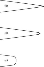 Figure 15.30. Trailing edge profiles of the three NACA0012 airfoils under study. (a) 0.5 percent truncation, (b) 2 percent truncation, (c) 10 percent truncation.
 |
this remains true even at the highest Reynolds number of the study. However, it may not be true for the three-dimensional simulation. In this study, the angle of attack is set at zero degree. This is to keep the flow and, hence, the tone generation as simple as possible. At a high angle of attack, separation bubble and open separation often occur on the suction side of the airfoil. Under such conditions, other tone generation mechanisms may become possible, but this is beyond the scope of this study.
 |
|
The governing equations are the dimensionless Navier-Stokes equations in two dimensions and the energy equation. Here, the length scale is C (chord width), velocity scale is aO (ambient sound speed), time scale is C/aO, density scale is pO (ambient gas density), pressure and stress scales are pOaO. These equations are as follows:
U is the free stream velocity, M is the Mach number, Re is the Reynolds number based on chord width. Both viscous dissipation and heat conduction are neglected in the energy equation as the Mach number is small.


