
Our heavyweight helicopter equal in the world does not have
In Rostov started production of the most load-lifting rotary-wing car The Russian holding «Helicopt[...]

Everything about aircrafts and helicopters. News and events in aviation worldwide. Civil, transportation, military helicopters and airplanes.

Everything about aircrafts and helicopters. News and events in aviation worldwide. Civil, transportation, military helicopters and airplanes.

Everything about aircrafts and helicopters. News and events in aviation worldwide. Civil, transportation, military helicopters and airplanes.

Everything about aircrafts and helicopters. News and events in aviation worldwide. Civil, transportation, military helicopters and airplanes.


15.1 GENERAL POINTS
A complete account of helicopter aerodynamics, even a very simple one, would require another book. A full analysis would fill, and does fill, many books, necessarily of a highly mathematical and specialised kind. An excellent non-technical introduction to the subject is to be found in John Fay’s book, The Helicopter, History and How it Flies. There are several very good practical guides to radio control model helicopters, some of which are listed at the end of this chapter. All that will be attempted here is to give a very brief account of some aspects of the helicopter rotor of particular interest to the aerodynamicist.
15.2 THE ROTOR AS A PROPELLER
The basic idea of the helicopter is simple enough at first sight A propeller rotating round a vertical axis with suitable blade pitch and power is able to carry an aeroplane straight up in a vertical climb. A helicopter rotor is a very large propeller adapted to give all the support needed for flight without any fixed wing surfaces.
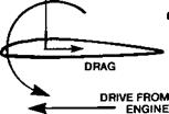
Most of what has been said already about propellers may therefore be applied, with necessary changes, to rotors. Each rotor blade is of appropriate aerofoil cross section and generates lift because it meets the airflow at a positive angle of attack. Like a propeller blade, a rotor blade may stall if the angle of attack is too large. The forces upon it are resolved into lift and drag and there is a pitching moment, the last being zero if the profile is symmetrical (Figure 15.1). Because the blades are usually of very high aspect ratio and slender, they tend to flex in flight and severe stresses are set up. Strong centrifugal forces

![]()
 PITCHING MOMENT fTWISTS BLADE]
are caused by the rapid rate of rotation. As with a propeller, the tips achieve much greater airspeeds than the roots and on full-sized rotors, high Mach numbers are reached and compressibility and noise problems arise.
Like a propeller, the drag of the rotor, consisting of profile and vortex drag, sets up a strong torque reaction at the hub. In twin rotor helicopters, the two rotors turn in opposite directions and cancel each other’s torque. The first truly successful helicopter, the Focke Achgelis of 1936, was of this kind. With the much more common single rotor arrangement, the torque is trimmed out by a small second rotor set on a boom with its plane of rotation at right angles to the main rotor disc. By changing the speed and pitch of the blades of the tail rotor, varying torques from the main rotor can be balanced in all flight conditions. Flow conditions around the torque-balancing rotor are extremely complex because it works in air greatly disturbed by the main rotor. It is known that considerable differences in control and handling of a helicopter arise when the tail rotor is arranged as a ‘tractor’ on one side of the supporting boom, instead of as a ‘pusher’ on the other.


