Our heavyweight helicopter equal in the world does not have
In Rostov started production of the most load-lifting rotary-wing car The Russian holding «Helicopt[...]

Everything about aircrafts and helicopters. News and events in aviation worldwide. Civil, transportation, military helicopters and airplanes.

Everything about aircrafts and helicopters. News and events in aviation worldwide. Civil, transportation, military helicopters and airplanes.

Everything about aircrafts and helicopters. News and events in aviation worldwide. Civil, transportation, military helicopters and airplanes.

Everything about aircrafts and helicopters. News and events in aviation worldwide. Civil, transportation, military helicopters and airplanes.


An option for securing the longitudinal stability of a wing-in-ground-effect craft consists of using the tandem scheme with both wings operating at small relative ground clearances.
The parameters of the front and aft wings of the tandem should be selected to provide an appropriate stability margin. Owing to the fact that the interaction effects of small clearances are of the order of О (/г), one can perform a qualitative analysis of the stability of a tandem foil configuration based on the aerodynamics of a single foil in extreme proximity to the ground. Here some results are presented of an analysis of the static stability margin of a tandem foil configuration (Л = oo) for the particular case when the foils have equal chords and ground clearances hi = /12 = h = 0.1. In the calculations, the center of gravity of the tandem was assumed to coincide with the trailing edge of the front foil. The distance between the foils constituted 20% of the chord.
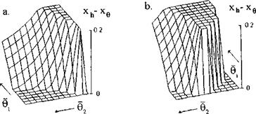
Figure 11.6a depicts the magnitude of the static stability margin versus the adjusted pitch angles (related to the ground clearance, i. e., #1,2 = #1,2/h) of the front and rear foils when both foils are flat. We can conclude upon examination of this figure that, whereas a single foil is not statically stable, addition of another foil can result in a positive static stability for certain combinations of adjusted pitch angles. It can also be observed from Fig. 11.7a that for better stability it is advisable to put more loading upon the front foil [185].
The static stability of longitudinal motion for a tandem can be further enhanced by curving the lower surface(s) of one (or both) foil(s). Fig. 11.6b reflects the increase in the reserve of the static stability of the tandem when the front foil has a sine type curvature with amplitude s = 0.2h — 0.02.
A simplified analysis of the influence of the design parameters on the position of the characteristic centers and the static stability of a tandem
|
Fig. 11.6. 3 – D charts of the static stability of a tandem comprising two foils versus their adjusted pitch angles related to the ground clearance hi = /12 = h: a. both foils are flat, b. front foil has a sine curvature. |
configuration can be conducted within the linear theory of a foil in in extreme ground effect; see chapter 3. Assuming that the wings of the tandem are flat, have identical chord lengths C0, and an infinite aspect ratio, we can derive the following formulas for the abcissas of the center of pressure (жр), the center of height (rch)> and center of pitch (xg):
P — Xp Ls 1.
In these formulas the following notations have been introduced: Cyi and Cy are, respectively, the lift coefficients of the front wing (based on its reference area) and the tandem as a whole (based on the sum of the reference areas of the front and rear wings); Ls is the distance of the trailing edge of the front wing from the leading edge of the rear wing, related to C0; and = /12 f h, i. e., the ratio of the relative ground clearance of the rear wing to that of the front wing. Introduction of the lift coefficient of tandem as a whole is practical for the analysis because for a selected wing loading and cruise speed, the vehicle should be designed for a fixed magnitude of the cruise lift coefficient.
Observation of the formula allows us to draw some preliminary conclusions about the position of characteristic centers in the case under consideration. In particular,
• when design ground clearances of the front and rear wings are indenti – cal,3 the center of height coincides with the center of pressure xh = xp. As per Zhukov[175], the closeness of these centers to each other improves controllability of the vehicle; see also 11.2.3,
• in the case under consideration, for fixed magnitudes of the lift coefficients of the front wing and the tandem as a whole, the position of the center of pressure does not depend upon the ratio /12/^1-
Based on the analytical results presented above, the simplified analysis of the stability is reduced to a calculation of the positions of the three characteristic centers and the static stability margin SSM = xh — xg versus the parameters Cyi, Cy, Ls, and /%. The results of some calculations are presented in Figs. 11.7-11.11.
 |
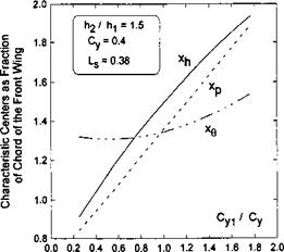
Figures 11.7-11.9 exemplify the effect of the ratio of the design ground clearances /12/^1 of the tandem wing elements upon the dependence of the positions of the characteristic centers on Cyi/Cy. One can conclude from observation of these graphs that by varying the design ratio of the ground clearances of the front and rear wings of the tandem, we can bring the center of height to different positions coincident with the center of pressure, upstream or downstream of the center of pressure.
|
Fig. 11.9. The calculated relative abscissas of the aerodynamic centers of a tandem craft versus the lift coefficient of the front wing as a fraction of the total lift coefficient, /12/hi = 1.5. |
|
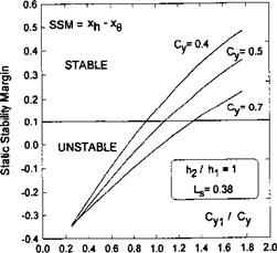
Fig. 11.10. The calculated static stability margin SSM = Xh~ x$ of a tandem craft versus the lift coefficient of the front wing as a fraction of the total lift coefficient, h2//ii = 1,LS = 0.38 for different magnitudes of the total lift coefficient. |
Figures 11.10 and 11.11 show more explicitly whether the vehicle is stable and what is the dependence of its static stability margin SSM = — xq on
different design factors. In all cases the calculations confirm a conclusion of [185] that for better static stability, it is desirable to put more loading onto the front wing. Figure 11.10 shows that (for a fixed fraction of the front wing loading) reducing the lift coefficient of the tandem brings about the deterioration of static stability. In practical design terms this means,
|
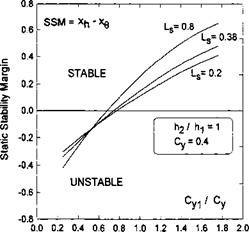
Fig. 11.11. The calculated static stability margin SSM = Xh — xg of a tandem craft versus the lift coefficient of the front wing as a fraction of the total lift coefficient, h2/h = 1 ,Cy = 0.4 for different magnitudes of the spacing between the wings of the tandem. |
for example, that for a prescribed speed of the vehicle, a reduction of wing loading may lead to a lower reserve of the static stability.
Figure 11.11 illustrates the effect of the spacing between the wings of the tandem. The conclusion here is straightforward: enlarging the distance between the wings entails augmentation of the static stability margin.
A question may arise why the tandem, even with flat (identical) wing elements can be designed to be statically stable, whereas an isolated single wing shows neutral static stability, see 11.2.1. A reasonable answer to this question is if the wing elements of the tandem secure height stability, the whole system acquires pitch stability.[70]