Our heavyweight helicopter equal in the world does not have
In Rostov started production of the most load-lifting rotary-wing car The Russian holding «Helicopt[...]

Everything about aircrafts and helicopters. News and events in aviation worldwide. Civil, transportation, military helicopters and airplanes.

Everything about aircrafts and helicopters. News and events in aviation worldwide. Civil, transportation, military helicopters and airplanes.

Everything about aircrafts and helicopters. News and events in aviation worldwide. Civil, transportation, military helicopters and airplanes.

Everything about aircrafts and helicopters. News and events in aviation worldwide. Civil, transportation, military helicopters and airplanes.


Somebody once referred to the future thus:
There is no future – it is just the past repeating itself!
In some ways this could be applied to the evolution of rotary-wing aircraft. The tilt wing, tilt rotor, compound and stopped rotor configurations have all come and gone and come again. In some particular instances a configuration is adopted by a manufacturer who has pursued it with a continuous programme of research and development. There will be many reasons why these things happen, but the learning process must play a part. Technologies, such as electronics and computing power, allied to a constantly improving set of methods open doors previously closed to the helicopter designer/engineer. These opening doors will encourage the revisiting of the various configurations which in most cases are devoted to ways of getting past the aerodynamic speed limit of the conventional main rotor system.
Any comments on the future have to express opinions particular to the author. I do not intend to cause upset and, particularly, do not wish to tread on any sensitive toes. If, however, I provoke argument – then that is healthy. You may think me wrong, but I hope you acknowledge that my comments are expressed with the best will in the world.
What follows is the result of consulting several papers [1-3] written on areas defining where rotary-wing development can be considered.
The experience of the 1982 Falkland Islands conflict showed a level of rotary-wing operations far exceeding the operations of any other type of aircraft.
The introduction of gas-turbine propulsion systems around 1960 began the move away from piston engines. The success of these prime-movers can be attributed to several factors, namely:
• Fuel efficiency.
• Advantages in use of internal space.
• The torque transferred to the transmission was of a smoother character with fewer fluctuations.
• No clutch was required.
Basic Helicopter Aerodynamics, Third Edition. John Seddon and Simon Newman. © 2011 John Wiley & Sons, Ltd. Published 2011 by John Wiley & Sons, Ltd.
These were in spite of considerably higher speed reductions.
Then, the introduction of a rotor speed governing system, replacing the hand throttle usually placed on the collective lever control. The rotor is best served by rotating at a constant rotor speed. This is for reasons of performance but, equally importantly, to permit vibration suppression systems to have a fixed set of rotor vibration frequencies which allows vibration control to be more effective.
The use of electric power is under close scrutiny, perhaps initially for the tail rotor. The transmission can also be carefully reassessed. Gear contact is a source of wear and potential difficulties so recently research is being directed at magnetic gear contact making way for a completely new transmission layout. The skeletal gearbox was examined in the 1970s when the load bearing of the main rotor gearbox was taken from the enclosing structure to a direct line through the gear shafts themselves. There was then a rudimentary enclosure – not required to withstand the helicopter weight – which effectively kept the rain out and the lubricant in.
Automatic flight control systems (AFCSs) appeared towards the end of the 1950s. Their immediate benefit is the release of the pilot from controlling the engine throttle, thereby providing a reduction in their workload. This permits the pilot to focus on the various tasks they have to accomplish during the particular operational sortie. The initial control was provided by analogue systems known as automatic stabilization equipment (ASE) which had a relatively modest 10% authority. To this were added height and speed locks for use in cruise.
In more recent times the AFCS is now based on digital processing – albeit with a similarly limited control authority. To move on further, the control of the aircraft by such a system must earn the trust and confidence of the rotorcraft industry and operators and only then can the control system be used to mould the handling qualities of new aircraft together with new operations.
Improvements in assessing and modelling the helicopter rotor are a constant source of effort. The helicopter rotor is a very demanding place and any experiments conducted on this require a robust and accurate instrumentation system. This will need a considerable amount of computing power to process the streaming data. This computing power is also providing opportunities to investigate the aerodynamic and dynamic features of the rotor. For instance, the interaction of blades with the vortex wake can be more closely examined and the blade structural dynamic behaviour, governed by the natural modes of vibration, can be determined with more confidence and increasing detail. Modern aerodynamic modelling requires the most subtle of blade characteristics to be known. It behoves such work to establish the blade dynamic behaviour when subjected to rapidly changing aerodynamic forces if further progress is to be made. However, one must always be prepared for the unexpected, and unacceptable vibration characteristics of the aircraft have caused significant disruption to helicopter development programmes.
In 1974, a programme of research into future rotor blade design was launched. It was the British Experimental Rotor Programme (BERP) and its initial designs and their children have been in existence ever since. BERP I to BERP IV trace a sequence of rotor blade developments driven by improvements in technical ability and understanding, engineering materials and manufacturing processes.
While programmes such as BERP enable rotor blade designs to be refined and reset standards for forward flight, the helicopter is still dogged by the rotor aerodynamics to pursue high-speed flight: namely, the perennial advancing/retreating-blade problem and at high speeds the requirement on the main rotor for high values of disc tilt. Rotor disc tilt will cause the fuselage to follow and with significant nose-down attitudes the attendant fuselage attitude can contribute a negative lift thereby loading the main rotor even more. Consequently, in order for a pure helicopter to be effective with a high cruise speed, the payload carried must be sacrificed for the weight of the mechanical systems at an increasing rate, particularly if the cruise speed exceeds 170 knots. This difficulty has caused designers to examine different types of rotarywing aircraft with emphasis on two, namely the Bell Boeing V22 tilt rotor and the Piasecki compound helicopter.
Now, in the early years of the twenty-first century, what can follow?
The pure helicopter is always required to have the capability to hover efficiently, but it is also required to fly efficiently at high forward speed and to be capable of achieving extremes of endurance and range. The phrase ‘high forward speed’ is rather vague but in pure helicopter terms it is relative to the normally accepted envelope of 170 knots. So the question is posed: is 170 knots the speed limit or are we looking at a faster transit speed? The follow-up to this is the influence this high speed will have on the operating cost and efficiency of the hover.
The operation of helicopters is progressively becoming more demanding on both the aircraft and the flight crew. The demands of operating from the confines of ships’ flight decks, oil rigs or, as is becoming more prevalent, operating close to difficult terrain when visibility is poor, such as brownout, place a high requirement on sensors, so the increasing need to operate the helicopter close to the ground can avoid hazards such as cliff faces, hills, bridges and general operation in and out of cover.
It is unfortunate that the helicopter has attracted, in the past, bad publicity as regards safety of operation. This has not gone unnoticed and strenuous efforts are being made to make a helicopter as safe as possible. Indeed, airworthiness can formally prove that the helicopter is safe.
The gauntlet is thrown down to the pure helicopter to meet these challenges. There is no doubt that being able to construct new and improve existing theoretical methods will influence the design process with this knowledge and bring it to the aircraft.
The rotor blade has, pretty much so far, been a passive device. It retains its shape and only in recent years have the dynamic characteristics been used in the search for increased performance with aeroelastic tailoring. Progress now requires the consideration of active systems such as tip-jet blowing and boundary layer control. Also a considerable amount of effort is now being directed at trailing-edge morphing, where internal devices physically deform the aerofoil section. External flaps have been used for many years, but the ability to achieve these effects while avoiding an external device with its controls is seen as a step forward.
The rotor head is now increasingly using flexures rather than conventional hinges. These benefit the drag through aerodynamic cleanliness and remove a considerable burden of maintenance on the articulated rotor. A most influential benefit is the effect of a flexure system on the flight behaviour.
This naturally turns attention to the handling qualities of the helicopter. The control laws used to aid the pilot are now benefitting from the use of a greater level of embedded intelligence with the attendant ability to tailor the helicopter’s flying qualities for a particular task.
A problem with the pure helicopter has always been the method of torque control to react against the torque supplied to the main rotor and to give the pilot sufficient yaw control – usually in difficult circumstances. The open tail rotor has been used for many years, but alongside this there has been the introduction of the fenestron, the NOTAR circulation – controlled tail boom, and maybe a return to the tip-jet-driven main rotor which has no need for a specialized yaw control device.
In addition to acceptable handling qualities, the aspect of safety should be considered. In the distant past, inspections and component life were used to determine flight safety. In more recent
times, the ability of sensing systems to monitor the most critical of the helicopter components and to observe the vibration levels at different parts of the aircraft has created the Health and Usage Monitoring System (HUMS). This has improved the airworthiness levels considerably, but the future is now to use these systems to predict the degradation of a component or system so that replacement or servicing can be scheduled so that the aircraft can operate safely but the maintenance schedule will not be compromised. This is the prognostic version of HUMS. The observation of the aircraft by HUMS can provide the ability to measure fatigue giving the Fatigue and Usage Monitoring System (FUMS). All of this requires the use of the most modern and advanced electronic systems.
Or maybe new configurations will provide the way. A considerable number have been proposed or indeed flown over the years. The Sikorsky Advancing Blade Concept (ABC) of the late 1960s and early 1970s fitted to the S69 aircraft overcame the advancing/retreating-blade conflict by using a stiff coaxial rotor system which effectively relied on the advancing side of both rotors to provide the performance. Another direction was the return to the stopped rotor in the guise of the X Wing project of Sikorsky/NASA in the 1980s. It took off in the conventional way and then proceeded into forward flight under auxiliary propulsion. Use of blown blades allowed the rotor to achieve roll trim, especially as the rotor was slowed to a stop with the four – bladed rotor orientated in a 45° position giving rise to the X Wing name. The blowing sequences had to vary with blade radial position and blade azimuth making the computing effort considerable. The blades, which are normally kept in shape by the centrifugal force of rotation, are now required to support the aircraft by the structure only.
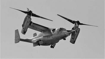
The tilt rotor concept returned and a great deal of effort was devoted to it in the 1970s, 1980s and 1990s, initially with the Bell XV-15 concept vehicle from which emerged the production version, which is the Bell Boeing V22 Osprey, now in service with the US Marine Corps – see Figure 9.1.
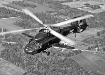
The tilt wing has not appeared in recent times. However, the one configuration which is seeing recent effort is the compound helicopter. The Piasecki Corporation has, for many years, worked on this type of vehicle, with particular attention paid to the tail unit providing the yaw control. By using a propeller with a cascade of vertical aerofoil louvres to deflect the downwash from the propeller in a sideways direction, the required yaw control is achieved. The louvres can be realigned so that the propeller can now act as a direct propulsion device removing this
|
|
|
Figure 9.2 S-70 Blackhawk compound development aircraft (Courtesy Piasecki Corp.) |
requirement from the main rotor. The most recent application is that of a modified S-70 Blackhawk as shown in Figure 9.2.
One significant benefit of a thrust compound helicopter is that by relieving the main rotor of the need to provide propulsion, the aircraft attitude can be kept under close control. Essentially the pilot now has the ability to control both components of force rather than the main rotor supplying the vector sum. This has immediate benefits for passengers in a civil aircraft and keeping weapons on target in a military helicopter. For both variants the ability to slow to a halt can now be achieved without the attendant problem of a high nose-up attitude which can severely reduce the pilot’s view of the landing site.
The 1950s saw the development of the Fairey Rotodyne which is a compound helicopter but uses tip-jet drive in and around the hover. In forward flight it transfers to an autogyro mode whereby the power to the blade tip jets is cut off and the twin airscrews provide the necessary forward propulsion. It still holds interest – even today.
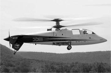
The most recent introduction to the compound helicopter stable is the Sikorsky X2 as shown in Figure 9.3.
This has a powered coaxial main rotor with a pusher propeller. On 15 September 2010 it achieved a speed of 262 knots.
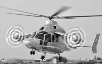
Within days of the X2 achieving its high-speed record-breaking run, Eurocopter unveiled its X3 demonstrator – Figure 9.4.
This uses separate propellers mounted on stub wings either side of the main fuselage. It has a normal single main rotor. It is interesting that the idea of using forward-facing propellers to give yaw control and forward propulsion was also seen on the Fairey Gyrodyne.
A concept already mentioned is the stopped or slowed rotor. This can be seen in various developments, one being the CarterCopter which is based on the slowed rotor. A recent statement by Boeing had indicated a return to the idea of a stopped rotor. Boeing is developing a rotor that has a large thin disc at the centre of the main rotor hub. The blades are extendable/ retractable being housed within the disc. If a stopped rotor is to work it will encounter extremely large advance ratios as the rotor slows to a halt. This places a high level of difficulty on the
|
Figure 9.3 Sikorsky X2 compound helicopter (Courtesy Ashish Bagai, Sikorsky Aircraft) |
blades at 90° and 270° azimuth. The disc provides a safe location for the blades as the advance ratio increases beyond the normal limits.
One recent development has been the use of simulation on relatively inexpensive computer systems. It is, of course, imperative that the fidelity is of the highest quality. In the past this has required very expensive equipment; however, the quality of simulation software, which can be purchased on the high street, has improved a very great deal in the past few years and helicopter landings on ships are quite possible with inexpensive computing and software. The provision of a full moving base simulator will still be very expensive, but even that could fall to the emergence of computing power that would have been staggering only a few years ago.
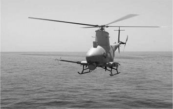
The discussion has concentrated on the piloted helicopter. Rotorcraft with their unique ability to VTOL operation enable them to be considered for use as UAVs. An example is the Firescout as shown in Figure 9.5.
|
|
|
Figure 9.5 Northrop Grumman Firescout UAV helicopter (Courtesy US Navy) |
It is designed to operate from ships, spending in excess of 8 hours on station. It can accept a range of payloads.
So far, the discussion has been based on the Earth. In the early years of the twenty-first century, the use of a rotorcraft for exploration of the planet Mars was considered. The weight limitations are of obvious major concern but the planet has a very different atmosphere. The ‘air density’ is about 1% of that on Earth. This immediately places a very high burden on the induced power in the hover, which it will have to do as a matter of course. It will be subjected to high wind speeds and so the VTOL capability will exact its price.
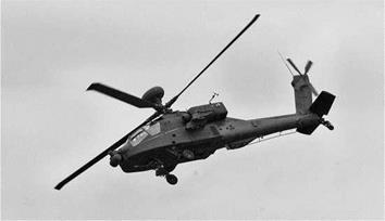
In the author’s opinion, the helicopter will never replace the role of a civil fixed-wing aircraft, particularly long haul. The helicopter will supply a niche market and do it well and with increasing efficiency and safety. To ask for more is unrealistic. It will have to conform to evermore stringent regulations concerning pollution. This, of course, involves noise generation and many efforts have already been used to address this problem. An example is the scissor tail rotor of the Apache as shown in Figure 9.6.
|
|
This chapter is a discussion on what might happen. What will happen is another matter. Having worked in helicopters for 40 years now, I am very set in my ways. The baton now passes to another generation who will bring new and controversial ideas to the subject. If my 40 years have taught me anything, it is that helicopter engineers can be disruptive types who seem to specialize in asking the most awkward questions. Long may it continue!
References
1. Byham, G. M. (2003) The future of rotorcraft, Aero. J., 1072, 377-387.
2. Aiken, E. W., Ormiston, R. A., and Young, L. A. (2000) Future directions in rotorcraft technology at Ames research center, AHS 56th Annual Forum, Virginia Beach VA, May 2-4.
3. Young, L. A., Aiken, E. W., Gulick, V., Mancinelli, R., and Briggs, G. A. (2002) Rotorcraft as Mars scouts, IEEE Aerospace Conference, Big Sky, March 9-16.