Our heavyweight helicopter equal in the world does not have
In Rostov started production of the most load-lifting rotary-wing car The Russian holding «Helicopt[...]

Everything about aircrafts and helicopters. News and events in aviation worldwide. Civil, transportation, military helicopters and airplanes.

Everything about aircrafts and helicopters. News and events in aviation worldwide. Civil, transportation, military helicopters and airplanes.

Everything about aircrafts and helicopters. News and events in aviation worldwide. Civil, transportation, military helicopters and airplanes.

Everything about aircrafts and helicopters. News and events in aviation worldwide. Civil, transportation, military helicopters and airplanes.


Because the oblique (lying wing can adjust its sweep angle for each Mach number, it achieves higher lift-to-drag ratios than conventional configurations up to Mach 2.0. A conceptually good way of looking at this is presented by:
Dr., = Friction + + 1МІ (108)
I**2 q2nx] nX2
The first term in this expression. Friction, can be assumed constant. The second term is the induced drag. L represents the lift, q the dynamic pressure and b the aircraft span. The larger the span the less the induced drag for a given lift. The third term is the wave drag due to lift. M is the Mach number and X] represents the (weighted) average characteristic length of the aircraft’s pressure signal. For low supersonic Mach numbers the lengths Xj and X2 arc close to the
projected length of the configuration in the direction of flight. V in the third term represents the volume of the configuration. So the reduce the wave drag it is necessary to have a very long aircraft.
Since we need both a great span and a great length to minimize the drag of a configuration it makes sense to consider a variable diagonal distnbuton of volume and lift. Because the sweep is variable such a configuration can minimize drag for any Mach number.
Thick supercritical sections arc a key technology for the oblique flying wing. Sections as thick as 19 % will enhance the utilization of the wing volume reduce of structural weight.
|
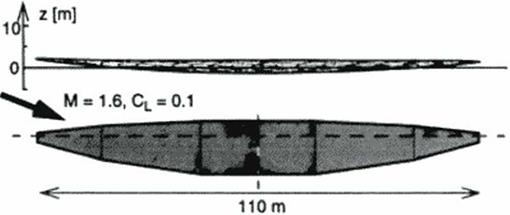
Figure 122 shows the example resulting from (he author’s direct wing design method as described in chapter 16. see the OFW case study there (Figure 93). In view of the limitations of the artificial stability and control system the wing was trimmed around 32% of the chord. The wing is naturally stable in front of this location.
|
Tltc global design (wing area, thickness, aspect ratio etc.) was optimized for minimum total operating cost (406) The detailed design originated out of the optimization of the shape for minimum drag at cruise without moments around the center of gravity. Additional constraints were imposed to fit the payload according to the standard previously discussed. The design clearly shows the wing parabolic dihedral (bend) proposed by R. T. Jones. A bent oblique wing creates a linear twist distribution which compensates for the loading up of the aft w ing due to induced effects.
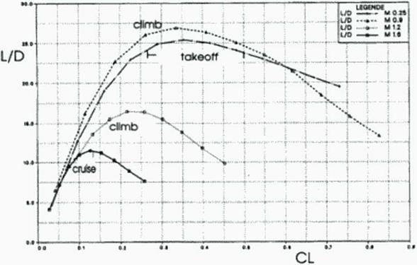
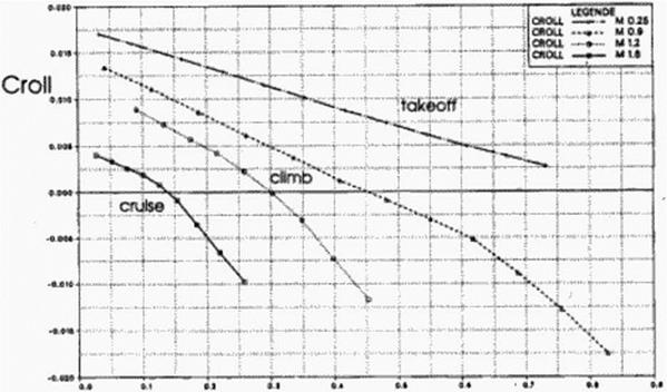
Figure 123 – Figure 127 show the aerodynamic forces and moments during flight for the full scale transport using this optimized shape. Notice that the aircraft flies only in very narrow corridors of angles of attack. The lift-to-drag ratios arc in excess of 25 at subsonic speeds and in excess of 11 at supersonic speeds. The pitching and rolling moments cannot be decoupled: if one analyzes the moments involved, it turns out (hat the neutral point moves along the center of gravity line. This is caused by the upwash induced from the forward w ing on the aft wing. For symmetric swept aircraft this phenomenon only causes increased pitching moments, but for oblique w ings this causes rolling moments.
 |
ALPHA
|
|
 |
|
Figure 126 Lift Coefficient Versus Rolling Moment Coefficient |
|
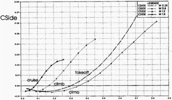
Figure 127 Lift Coefficient Versus Side Force Coefficient |
So, in a sense, the aircraft is close to neutrally stable about the long axis Under normal flight conditions there is no side force on the aircraft; at higher angles of attack, the leading edge suction produces a side force to the right.
The oblique wing designed with this new method had drag levels comparable to the theoretical minimum drag for oblique w ings of the same volume, lift and length. The estimates of oblique wing theoretical minimum drag by Jones and Smith [4011 arc therefore applicable to more realistic trimmed configurations.