Our heavyweight helicopter equal in the world does not have
In Rostov started production of the most load-lifting rotary-wing car The Russian holding «Helicopt[...]

Everything about aircrafts and helicopters. News and events in aviation worldwide. Civil, transportation, military helicopters and airplanes.

Everything about aircrafts and helicopters. News and events in aviation worldwide. Civil, transportation, military helicopters and airplanes.

Everything about aircrafts and helicopters. News and events in aviation worldwide. Civil, transportation, military helicopters and airplanes.

Everything about aircrafts and helicopters. News and events in aviation worldwide. Civil, transportation, military helicopters and airplanes.


Figure 118 shows the present baseline Daimler Benz Aerospace Airbus Oblique Flying Wing layout designed for 250 passengers and a 5000nm range at a cruise Mach number of 1.6. The passengers are accommodated inside cylindrical hulls inside the constant chord center section. All oblique flying wings considered in this work have the same chord of about 15 m. At this chord the 19 % thick airfoil can hold two five-abreast hulls. The interior layout conforms to the A320 standard: its center aisle is 2.20 m high and the doors are 1.95 m high. Since passengers are accelerated sideways during takeoff, shoulder straps w ill be required. Other layouts in which passengers will not be accelerated sideways during takeoff and landing arc optional. Entrance doors are placed in the nose of the aircraft. The emergency exits are found in the nose and trailing edge side of the passengers cabin, and can be reached by access ramps that lead to the top of the wing.
The pressurized hulls are laid along the spanwise direction and carry structural loads. The floor structure has a 50 cm crash zone. Figure 118 shows the cabin cross-section at the wing’s zero incidence. The cabin is lilted with respect to the zero incidence so that the range of floor incidences never vanes more than 3° from a level floor. The cargo is next to the passenger cabin, rather than under the floor, and offers space to containers up to 1.70m, so standard A340 LD3 containers can be fit.
Another deviation from the wide-body standard is the cockpit. Space is provided in the nose of the cabin to house two pilots. The pilot will have good visibility dunng approach and climb. His field of vision is 20° left. 90° nght at takeoff and landing, similar to the со pilots view in FAR 25.777. The oblique wing is swept with the left tip forward so the pilots have an unobstructed right view This is important with respect to the current air traffic nght-of-way rules.
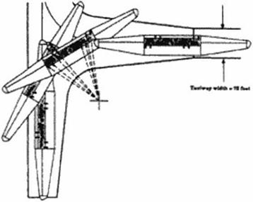
Figure 118 also shows the gear layout. The undercarriage has up to four main legs depending on maximum takeoff weight. The main landing gear is in the nose. A smaller gear is aft of the cabin. The best gear location is typically at 35% of the span for minimum structural weight. A constraint of 35 meters has been placed on the gear track so the aircraft can operate on runways of 50 m width. Figure 119 shows that it is necessary to have main gear steering to execute a turn. Takeoffs and landings are executed by rotation around the long aircraft axis. Apart from this unusual selection of the axis, the takeoff run is similar to that for a DC-3.
|
|
Figure 119 Runway Turn, Ref. (407)
Four fuel tanks are distributed over the span to reduce the structural loads during taxiing. To minimize trim drag, the center of gravity position can be moved by a fuel trim system as the case with all Airbus aircraft.
The nacelle» arc distributed along the span The ihrusl-vcetoring nacelle design shown in Figure I IS has the inlet almost parallel to the leading edge. It is comparable to the Olympus nacelle turned 90° around its long axis. At cruise the airflow is not turned, but at takeoff the inlet sucks in air from the nght – just as Concorde at a high angle of attack sucks in the air from below the aircraft -. Inlet bypass doors prevent the air from separating in the nozzle. The nozzle
then vectors the thrust to propel the aircraft at the takeoff sweep of 45°,
In view of the limitations of the artificial stability and control system the nacelles arc placed as far forward as possible; synergistic, cabin noise and aerodynamic considerations dictate their placement outside the passenger cabin. Engine core or fan bursts do not cause damage to the pressure hull, therefore greatly reducing the critical risk of sudden decompression above 13000 m. To increase engine-out yaw control and to minimize the wave drag and wing stress, the engines were podded in four nacelles. The engines are of conventional turbofan design with a low bypass ratio. Such an engine placement would not lead to any significant additional drag (3 counts) for Mach numbers between 1.4 and 1.8.
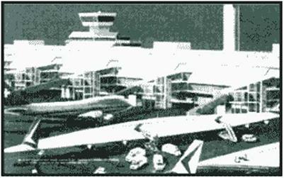
This baseline configuration avoids one of the classical objections against the flying wing, namely that it docs not have stretch potential, is not true for our baseline configuration. We can simply add center cabin sections of the wing’s maximum thickness. It can be easily shown that this will even increase the L/D of the configuration. Although the OFW is very long in comparison to other aircraft. Figure 120 shows that it can fit a realistic airport slot. The current designs fit a Very Large Transport slot sized at 80 m x 80 m.
|
|
 |