
Our heavyweight helicopter equal in the world does not have
In Rostov started production of the most load-lifting rotary-wing car The Russian holding «Helicopt[...]

Everything about aircrafts and helicopters. News and events in aviation worldwide. Civil, transportation, military helicopters and airplanes.

Everything about aircrafts and helicopters. News and events in aviation worldwide. Civil, transportation, military helicopters and airplanes.

Everything about aircrafts and helicopters. News and events in aviation worldwide. Civil, transportation, military helicopters and airplanes.

Everything about aircrafts and helicopters. News and events in aviation worldwide. Civil, transportation, military helicopters and airplanes.


Loss of control is a most serious event, and huge emphasis on safety in the aviation world is there to ensure that all possible events that might lead to a loss of a flight critical function are thoroughly examined and steps taken in the design process to ensure that such losses are extremely improbable. In military use, when helicopters can be exposed to the hazards of war, steps are sometimes taken to build in additional levels of redundancy in case of battle damage. For example, the AH-64 Apache features a back-up, fly-by-wire control system that can be engaged following a jam or damage in the mechanical control runs. The tail rotor is particularly vulnerable to battle damage, and a study carried out by DERA and Westland for the UK MoD and CAA, during the mid-late 1990s, identified that tail rotor failures occur in training and peace-time operations at a rate significantly higher than the airworthiness requirements demand. In the following section some of the findings of that study are presented and discussed.
Tail rotor failures
We broaden the scope to include both types of tail rotor failure: drive failure, where the drive-train is broken and a complete loss of tail rotor effectiveness results, and control failure, where the drive is maintained but the pilot is no longer able to apply pitch to the tail rotor. Both examples result in a loss of the yaw control function and can occur because of technical faults or operational damage. References 8.43 and 8.44 describe a programme of research aimed at reviewing the whole issue of tail rotor failures and developing improved advice to aircrew on the actions required, following a tail rotor failure in flight. The activity was spurred by the findings of the UK MoD/CAA Tail Rotor Action Committee (TRAC), which in particular were as follows (Ref. 8.9):
(a) Tail rotor failures occur at an unacceptably high rate. MoD statistics between 1974 and 1993 showed a tail rotor technical failure rate of about 11 per million flying hours; the design standards require the probability of transmission/drive failure that would prevent a subsequent landing to be remote (<1 in a million flying hours, Ref. 8.42); a review of UK civil accident and incident data revealed a similar failure rate.
(b) Tail rotor drive failures are three times more prevalent than control failures.
(c) There appear to be significant differences in the handling qualities post-tail rotor failure, between different types (e. g., some designs appeared to be uncontrollable,
and the probability of an accident resulting from a failure is greater with some types
than others), although there is a dearth of knowledge on individual types.
(d) Improved handling advice would enhance survivability.
TRAC recommended that work should be undertaken to develop validated advice for pilot action in the event of a tail rotor failure for the different types in the UK military fleet, and also that airworthiness requirements should be reviewed and updated to minimize the likelihood of tail rotor failures on future designs. In the study that followed, validation was classified into three types – validation type 1 corresponding to full demonstration in flight, validation type 2 corresponding to demonstration in piloted simulation combined with best analysis and validation type 3 corresponding to engineering judgement based on calculation and also read-across from other types. It was judged that the best advice that could be achieved would be supported by type 1 validation for control failures and type 2 validation for drive failures.
The study, reported fully in Ref. 8.44, drew data from a variety of sources including the MoD and CAA, the US Navy, Marine Corps and Coast Guard and the US National Transport Safety Board (NTSB). The overall failures rates were relatively consistent across all helicopter ‘fleets’ and occurred in the range 9-16 per million flying hours. Recall that civil transport category aircraft are required to have a failure rate for flight critical components of no more than 1 in 109 flying hours. Of the 100 ‘tailfails’ in the UK helicopter fleet between the mid-70s and mid-90s, 30% were caused by drive failure and 16% by control failure or loss of control effectiveness. Tail rotor loss due to collision with obstacle or vice versa accounted for 45% of the failures.
When investigating flying qualities in failed conditions, two different aspects need to be addressed – the characteristics during the failure transient and post-failure flying qualities, including those during any emergency landing. Both are, to some extent, influenced by the flight condition from which the failure has occurred. For example, the failure transients and optimum pilot actions will be quite different when in a low hover compared with those in high-speed cruise, well clear of the ground. The required actions will also be different for drive and control failures. Furthermore, in the case of control failures, the aircraft and appropriate pilot responses will depend on whether the control fails to a high pitch or low pitch, or some intermediate value, perhaps designed in as a fail-safe mechanism to mitigate the adverse effects of a control linkage failure.
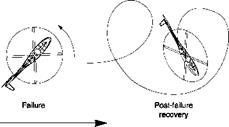
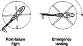
Reference 8.44 describes a flight trial, using a Lynx helicopter, where control failures were ‘simulated’ by the second pilot (P2) applying pedals to the failure condition. P2 held the failed condition, while P1 endeavoured to develop successful recovery strategies using a combination of cyclic and collective. The high-pitch control failure mode results in a nose-left yaw (for anti-clockwise rotors), the severity of which depends on the initial power setting and aircraft speed. For example, the magnitude of control and yaw excursions will be greater from flight at minimum power speed than cruise. Accompanying the yaw will be roll and pitch motions, driven by the increasing sideslip. In the flight trials, a number of different techniques were explored to recover the aircraft to a stable and controllable flight condition. For failures in highspeed cruise, attempts to decelerate through the power bucket to a safe-landing speed were unsuccessful; the right sideslip (left yaw) built up to limiting values, and controlling heading with cyclic demanded a very high workload. A successful strategy was developed as illustrated in Fig. 8.38.
|
|
|
|
||||
|
|||||||
|

![]()
A high-power climbing turn to the left gave a sufficiently stable flight condition so that deceleration could be accomplished without the aircraft diverging in yaw. The aircraft could then be levelled out at about 40 knots and a slow decelerating descent initiated. Gentle turns to both right and left (left preferred) were possible in this condition. The landing was accomplished by lining the aircraft up with the nose well to port and applying collective, and levelling the aircraft, just before touchdown to arrest the rate of descent and align the aircraft with the flight path. Running landings between 20 and 40 knots could be achieved with this strategy. In comparison, low thrust control failures resulted in the aircraft yawing to starboard. Reducing power then arrests the yaw transient and allows the aircraft to be manoeuvred to a new trimmed airspeed. During recovery it was important that the pilot yawed the aircraft with collective to achieve a right sideslip condition, so that collective cushioning prior to landing yawed the aircraft into the flight path.
 |
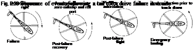 |
The drive failures were conducted in the relative safety of the DERA advanced flight simulator (see Chapter 7, Section 7.2.2). The trial was conducted within the broad framework of the flying qualities methodology with task performance judged by the pilot’s ability to land within the airframe limits, i. e., touchdown velocities and drift angle. Unlike a control failure, where the tail rotor continues to provide directional stability in forward flight, in a drive failure this stability augmentation reduces to zero as the tail rotor runs down. For failures from both hover and forward flight, survival is critically dependent on the pilot recognizing the failure and reducing the power to zero as quickly as possible. Figure 8.39 shows the sequence of events following a drive failure from a cruise condition. The aircraft will yaw violently to the right as tail
rotor thrust reduces. The study showed that a short pilot intervention time is critical here to avoid sideslip excursions beyond the structural limits of the aircraft. The pilot should reduce power to zero as quickly as possible by lowering the collective lever. Once the yaw transients have been successfully contained, and the aircraft is in a stable condition, the engines can be shut down and the aircraft retrimmed at an airspeed of about 80 knots. With the Lynx, this gives about a 20% margin above the speed where loss of yaw control is threatened. Any attempt to find a speed-power combination that enabled continued powered flight risked a yaw breakaway which could drive the aircraft into a flat spin. Gentle turns to right and left (more stable) were possible from the 80 knots autorotation. The pilot approaches the landing with the aircraft nose to starboard and, in this case, raising collective to cushion touchdown yaws the nose to port and aligns with the flight path.
Reference 8.44 describes typical examples of tail rotor failure that were in the database investigated. One such example involved a Lynx helicopter taking off on a test flight following the fitting of a new tail rotor gearbox. With the aircraft in a low hover, a ‘low power’ control failure occurred. To quote from Ref. 8.44,
As the aircraft lifted there was a slight yaw to the right which the pilot compensated for, but by the time the aircraft was established in a 10feet hover, a matter of only 2-3 seconds after launch, the aircraft was continuing to diverge to the right with full left pedal applied. The pilot called out full left pedal’, and the aircraft accelerated into a right hand spot turn over which the aircrew had no control. The aircrew recalled the AEO’s briefing and reduced the MR speed (which also reduced tail rotor speed and thrust), the yaw accelerated further, exacerbated by the fact that they were entering the downwind arc. The words of the briefing were then recalled ‘right hand turn equals low power setting, therefore increase NR’. The speed select lever was pushed forward to increase MR speed (and hence tail rotor speed and thrust), the yaw rate slowed down. The aircrew regained control of the aircraft and were able to land without further incident.
The Aircraft Engineering Officer (AEO) referred to here had actually led the tail rotor flight and simulation programme at DERA and is the first author of Ref. 8.43, and hence was very familiar with tail rotor failures. He had briefed the maintenance flight aircrew on actions to take in the event of a tail rotor failure. The advice proved crucial and the pilot’s actions averted a crash; the story is told in Ref. 8.45.
Reference 8.44 also identifies a number of candidate technologies that could mitigate the effects of tail rotor failure, e. g., warning systems, integrated with health and usage monitoring systems, emergency drag parachutes. This is an important line of development in the context of safety. The accident data highlight that drive failures on most types are not very survivable. The two illustrations used to describe the failure types show a straightforward transition from the failure through the recovery to the landing. In practice, however, the pilot is likely to be confused initially by what has happened (note above example where the pilot operated the speed select lever in the wrong direction initially) and can quickly become disoriented as the aircraft not only yaws, but also rolls and pitches, as sideslip builds up. Also, the accident/incident data show that on several occasions the pilot has successfully recovered from the failure but the aircraft has turned over during the landing. Tail rotor failures make undue demands on pilot skill and attention and the way forward has to be to ensure that designs have sufficiently reliable drive and control systems so that the likelihood of component failure is extremely remote in the life of a fleet. Reference 8.44 recommends that the Joint Aviation Requirements be revised to provide a two-path solution to ‘closing the regulatory gap’ in respect of tail rotor control systems. Firstly, fixed-wing aircraft levels of redundancy of flight critical components are required. Secondly, where redundancy may be impractical, ‘the design assessment should include a failure analysis to identify all failure modes that will prevent continued safe flight and landing and identification of the means provided to minimise the likelihood of their occurrence’.
Reference 8.44 also recommended that the ADS-33 approach of specifying failure transients (see next section) be adopted along with the collective to yaw coupling requirements and sideslip excursion limitations as a method of quantifying the effects of failure. Such criteria could also form the basis for evaluating the effectiveness of retrofit technologies, including contributions from the automatic flight control system. Tail rotor failures require the pilot to exercise supreme skill to survive what is, quite simply, a loss of control situation. If flying qualities degradation could be contained within the Level 3 regime, with controllability itself not threatened, then the probability of losing aircraft to such failures would be reduced significantly. Time will tell how effectively the recommendations of Ref. 8.44 are taken up by the Industry.
