Our heavyweight helicopter equal in the world does not have
In Rostov started production of the most load-lifting rotary-wing car The Russian holding «Helicopt[...]

Everything about aircrafts and helicopters. News and events in aviation worldwide. Civil, transportation, military helicopters and airplanes.

Everything about aircrafts and helicopters. News and events in aviation worldwide. Civil, transportation, military helicopters and airplanes.

Everything about aircrafts and helicopters. News and events in aviation worldwide. Civil, transportation, military helicopters and airplanes.

Everything about aircrafts and helicopters. News and events in aviation worldwide. Civil, transportation, military helicopters and airplanes.


Following simple sweep theory, we must examine the section design of an OFW for the normal component of velocity. At cruise conditions, the flow over an OFW is that behind the nearly conical shock wave emanating from the leading up. The wing is swept so that the component of this
flow normal to the wing’s leading edge will be sufficiently subsonic that a thick, shock-free airfoil may be found. We have assumed this sweep to be 60 degrees, and a frccstrcam Mach number of V2, giving a normal Mach number of 0.707. and a tangential component of 1.23.
Bocrstocl provides guidance on how thick a non-lifting airfoil might be if designed to be shock free (434). His results, and those of others, suggest it should be possible to design an 18% thick shock-free airfoil for a normal Mach number. Af*. of 0.76. This suggests to us that a 17% thick airfoil w ith a ct of 0.6. corresponding to a wing CL of 0.15. might be shock free for a Mach number of 0.7. The importance of a nearly shock-free design stems not from the wave drag of the cross-flow shock wave, but rather from the need to avoid separation arising from the adverse pressure gradient imposed on the boundary layer by this shock wave.
The normal component of the flow accelerates over the wing to become locally "supersonic.” The return of this component to "subsonic” cross flow is normally through a shock wave, just as it is on supercritical but not shock-free airfoils. This cross-flow shock wave adversely affects the boundary layer and. thereby, the wing’s lift and drag, just as it docs on subsonic. supercritical airfoils and wings [435].
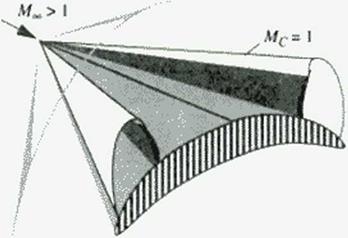
We cun fix our ideas for supersonic flow by considering supersonic conical flow past a wing with subsonic leading edges and conical camber. Such a wing will, unless designed using special tools, have a cross-flow shock wave like that depicted in Figure 146. While this flow is supersonic, the cross-flow plane equations arc mixed, being hyperbolic outside the conical shock wave and inside the local "supersonic” cross-flow region, but elliptic elsewhere
|
Figure 146 Embedded shock wave in a conical cross-flowr. |
The fictitious gas method for the design of supercritical airfoils, as discussed in Chapter 7. applies to conical supersonic flows as well. This extension to supersonic flows was first demonstrated by Snthuran [436]. Recently, wc have suggested that this method may apply to fully three-dimensional supersonic flows [437].
The axial component of the flow over the oblique wing causes a disturbance to the
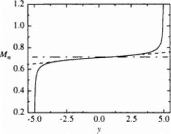
Mach number distribution of the normal component along the span. We may approximate this axial (low by that over a slender body of revolution whose cross-sectional area equals (hat of the wing, by using the linear theory. The resulting variation of the normal Mach number in the span direction is shown in Figure 147. We sec that (here is essentially a linear variation about the mid-chord value (y « 0) in the normal component of die Mach number, requiring different airfoil designs, or at least thickness, along the wing. We recognize, then, that the upper surface curvature and thickness of wing sections should be decreasing toward the w ing trailing lip. in order to avoid creating a cross-flow shock or increasing a shock’s strength if one has already formed. Our objective is to find out how well we might do in designing an OFW using supercritical airfoils that we develop and then appropriately blend to form the w ing.
|
Figure 147 Estimated variation in the normal Mach number component along the wing span; Mn • 0.707 at / = 0. Axial flow at 4, = 1.23, direction from left to right. |
As noted earlier, the OFW’ with the minimum (induced and wave) drag due to lift has an elliptic load. The OFW area distribution that minimizes the wave drag due to volume, or due to thtekness. is the Scars-Haack body for volume, and the Scars body for thickness. The former corresponds to a parabolic thickness distribution; the latter to a wing that has the same center section, but thinner outboard sections. In ihc studies reported here we have minimized the drag due to lift, and varied the thickness somewhat about a constant thickness to chord ratio. This corresponds to a nominal elliptic thickness distribution and results in more volume, and more wave drag, than necessary Thus these results should be considered very conservative, with perhaps twice the wave drag needed for the volume required for the passengers and fuel.