
Our heavyweight helicopter equal in the world does not have
In Rostov started production of the most load-lifting rotary-wing car The Russian holding «Helicopt[...]

Everything about aircrafts and helicopters. News and events in aviation worldwide. Civil, transportation, military helicopters and airplanes.

Everything about aircrafts and helicopters. News and events in aviation worldwide. Civil, transportation, military helicopters and airplanes.

Everything about aircrafts and helicopters. News and events in aviation worldwide. Civil, transportation, military helicopters and airplanes.

Everything about aircrafts and helicopters. News and events in aviation worldwide. Civil, transportation, military helicopters and airplanes.


Referring back to Table 8.7, showing the limits on attitudes and accelerations following a failure, the questions asked are – can this approach also apply to the response caused by external disturbances and are the same standards applicable? Table 8.11 shows the approximate pitch attitude transients at 3 s following the maximum pitch-up attitude. The values represent the changes in attitude from the maximum pitch-up rather than the initial pitch. This method leads to significantly greater transients in some cases but is justified because although the pilot would not be expected to allow the aircraft to pitch, he/she would have to apply forward cyclic to maintain the hover, which would exacerbate the pitch-down as the vortex core was crossed. The italicized numbers in Table 8.11 correspond to the cases where the Level 3 boundary is exceeded. SCAS disengaged results are also shown to illustrate the power of the SCAS and its positive impact on safety.
Similarly, Table 8.12 lists the 3-s perturbations in vertical acceleration. Only SCAS-off data are included; the SCAS does not change the level. In this case the reference conditions are the points where the larger negative bump begins (e. g., at 17.5 s for the FGR with the 5 ft/s crossing, Fig. 8.60).
If the pilot intervention time had been set at 1.5 s, the perturbations would have reduced to less than 50% of those in Tables 8.11 and 8.12 (with the possible exception of some SCAS-off cases); the italic cases would then be within the Level 3 boundary
Table 8.12 Transient vertical acceleration following the vortex encounter
Encounter velocity
![]() 5ft/s 10ft/s
5ft/s 10ft/s
|
Lynx SCAS off |
0.16 |
0.31 |
0.47 |
|
|
0.2 < nz < 0.4 |
||||
|
FGR SCAS off |
0.19 |
0.38 |
0.53 |
|
Aircraft |
|
Vertical acceleration in 3 seconds (g) |
|
ADS-33 Level 3 |
and most other cases would be Level 2. Combining the ADS-33 approach with the hazard categories in Fig. 8.44 leads to the following relationships:
• Handling qualities Level 1,2 – hazard category MINOR (safety of flight not compromised; slight reduction in safety margin or increase in pilot workload)
• Handling qualities Level 3 – hazard category MAJOR (safety of flight compromised; significant reduction in safety margins or increase in crew workload)
• Handling qualities Level >3 – hazard category HAZARDOUS (safety of flight compromised; large reduction in safety margin)
From this classification, and without considering control margins, it can be deduced that with a 3-s pilot intervention time the vortex encounter is HAZARDOUS, and with a 1.5-s intervention time the hazard category of the encounter is MAJOR. Both relate to the disturbance-induced flight path variations and the resulting risk of disorientation or loss of control. It should be noted that the largest attitude and acceleration changes occur after the initial pitch-up or negative bump. It could be argued that the pilot may at this stage be aware of the vortex encounter and the normal, full-attention, 0.5-s intervention time is more appropriate. The hazard category may then reduce to MINOR.
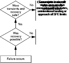
The effect of intervention time on the severity of the response can be investigated with the aid of the upset severity rating (USR) scale shown in Fig. 8.61. This scale is based on the pilot rating scale for failure transients described in Ref. 8.49 and already presented in modified form in Fig. 8.43. In summary, ratings A to E indicate tolerable severity and are awarded for cases where the disturbed excursions range from minimal, requiring no corrective action, to very objectionable, requiring immediate and intense pilot effort. For cases A through E, safety of flight is judged not to be compromised, and the hazard category is MINOR. Safety of flight is compromised with ratings of F through G, with excursions leading to possible encounter with obstacles, unintentional landing or exceedance of flight envelope limits; recovery is marginal and the hazard category is MAJOR (F) or HAZARDOUS (G). A rating of H means that the pilot judged recovery to be impossible with the hazard category CATASTROPHIC.
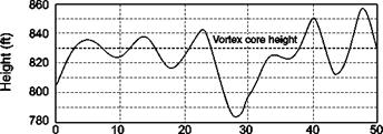
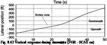
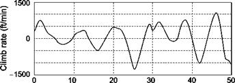
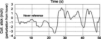
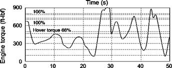
Figure 8.62 shows results from simulation trials at Liverpool with the FGR, with power, collective and vertical motion changes as the vortex is traversed at a nominal 10 ft/s. Also shown is the lateral track as a function of time with the core and outer boundaries indicated. The pilot reduces collective as the rotor enters the upwash of the advancing tail. The pilot is able to maintain height within ±10 ft during this phase of flight and reduces collective to command a very low engine torque, less than 20% of the hover setting. At about 25 s the vortex core is passed and as the helicopter moves into the downwash of the retreating tail, a descent rate of more than 1000 ft/min builds up in about 5 s, arrested by the pilot applying significantly more than the 106% transient torque limit. This transient overtorque limited the height loss to about 50 ft. Height and collective excursions when the helicopter experiences the downwash in the vortex tail are double those during the ‘upwash’ phase. The effect of the helicopter being rolled and accelerated to starboard during the core encounter, i. e., pushed out of the vortex, can be seen in the increased slope of the lateral position trace. An HQR of 7 and USR of F (MAJOR) were awarded for this case on the grounds that the torque limit was exceeded and the height excursion was beyond the adequate boundary of ±30 ft.
The ability to counteract the vertical motion induced by the vortex clearly depends on the available power and thrust margin. As shown in Fig. 8.62, the FGR was being flown with a power margin of more than 30%, reinforcing the point made earlier that the
 |
 |
|
Tolerable
 |
 |
|
Intolerable
Fig. 8.61 Upset severity rating scale
ADS-33 minimum standards for Level 1 performance margins in hover are insufficient in this respect. Another observation made by pilots during the trials related to the large changes in roll and yaw attitude during the encounter. Yaw motion can be induced by the lateral velocities in the lower and upper portions of the vortex. If the aircraft yaws by 90° then the pitch effects described earlier would transform into roll.
The solution to the wake vortex problem for runway-dependent aircraft approaching and departing along similar trajectories is to define minimum longitudinal separation distances. The severity of encounters can be catastrophic close to the ground, but the risk is lowered to an acceptable level by reducing the probability of occurrence through separation. When considering runway-independent aircraft and the associated
![]()
|
|
 |
concept of simultaneous, non-interfering operations (SNIOps), the problem is more complex and lateral separation of approach and departure flight paths also becomes a major issue. At any particular location, the positioning of a helicopter final approach and landing area can be optimized on the basis of prevailing winds and atmospheric conditions, fixed-wing aircraft landing and take-off patterns and the nature of the traffic at any particular time. Whether it will ever be acceptable to operate with this flexibility is another question, but the risk certainly needs to be carefully managed through flight path constraints and positioning of the terminal area ground operations. The most concerning result is the potential loss of height due to encounters with the downwash side of a vortex. Reference 8.64 documents an accident following a suspected encounter of a light helicopter with a vortex, and it was the vertical motion of the aircraft that most disturbed the crew prior to the loss of control and crash. Helicopters typically operate with fairly low power/thrust margins in hover (<10%). Although these may satisfy the handling standards for vertical performance, the results of both off-line and piloted simulations show that they may be wholly inadequate to overcome the effects of a vortex encounter. The situation will improve when some forward velocity has been gained and also when the helicopter has a rate of climb.
