Our heavyweight helicopter equal in the world does not have
In Rostov started production of the most load-lifting rotary-wing car The Russian holding «Helicopt[...]

Everything about aircrafts and helicopters. News and events in aviation worldwide. Civil, transportation, military helicopters and airplanes.

Everything about aircrafts and helicopters. News and events in aviation worldwide. Civil, transportation, military helicopters and airplanes.

Everything about aircrafts and helicopters. News and events in aviation worldwide. Civil, transportation, military helicopters and airplanes.

Everything about aircrafts and helicopters. News and events in aviation worldwide. Civil, transportation, military helicopters and airplanes.


At first we perform a preliminary airfoil design using the fictitious gas method. A 17.4% thick baseline airfoil is generated using the geometry tools described in Chapter 9 for a flow of Af * 0.707 with С/ = 0.6. For choosing the fictitious equations used in the Euler solver, we prescribe a new energy equation to change the equations inside a local supersonic region so that they remain elliptic there (413]. This results in a shock-free flow with a smooth sonic line, but the wrong gas law, inside the supersonic region. As described in Chapter 7. the correct mixed type structure of the transonic flow is recovered in the next step: supersonic flow recalculation by means of the method of characteristics, using the just calculated data on the sonic line for the initial values. This recomputation of the flow with the correct equations of state has a lower density in the supersonic flow and provides a modified, and thinner, airfoil design. The result is the slightly flattened section shown in Figure 6 of Chapter 7 with a thickness of 17%.
|
|
|
|
|
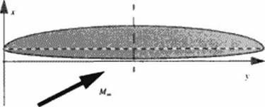
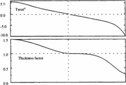
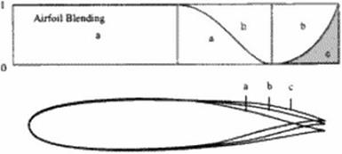
Figure 14# Wing geometry parameters: planform, twist distribution and thickness factor along span; support airfoils and their blending weight. |
We use this shock-free, redesigned airfoil as the center section for an OFW We take the planform to be comprised of two ellipses, as shown in Figure 148. w ith an overall 10:1 axis ratio providing an unswept aspect ratio of 12.7. Other airfoil sections are developed for slightly higher and lower Mach numbers based on the variation of the normal Mach number down the wing as determined previously using linear theory. We then use the geometry generator of Chapter 9 to determine a blending of candidate w ing sections. Numerical computations were performed using NASA Langley’s CFL3D (4381. И39]. To achieve the elliptic load distribution, twist is varied along the wing span. Die twist variation is linear near the center, strongly decreases at the trailing tip. and slightly increases at the leading tip But different Mach numbers and sweep angles require differing twists An elliptic loading is therefore best realized by bending the wing up at the tips. For simplicity we have used wing twist in our studies.
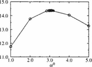
In Figure 148 we depict the blending of supercritical sections and the variation of twist used to achieve a nearly elliptic loading at the shock-free design point. Die twist was varied from – It) to -1-5.5 degrees; a wing section thickness factor varied from 0.3 to 1.5 from the trailing to the leading tip. Between the center section and trailing lip. the three support airfoils shown were blended to comprise the w ing This provided an inviscid L/D of 14.36 at a CL of 0.15 We explored the variation in L/D with angle of attack, as shown in Figure 149. We find the maximum l/D is 14.37 at а С/ of 0.146 Die inviscid pressure distributions at five span stations, the Spoil wise load distribution, and isotachs on three grid surfaces are depicted in Figure 84 These results correct those given earlier (437).
Using the skin friction estimate prov ided earlier gives a viscous L/D of 10.19. which is consistent with the result given in Chapter 19 Higher values are surely possible as the designed wing’s volume. 152,189 cubic feet, is considerably larger than that required.
|
L/D
Figure 149 Lift-u>-drag ratio as a function of angle of attack. • denotes the shock-free airfoil design point. |
|
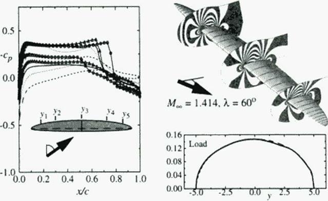
Figure 150 Pressure distributions at five span stations (y,-dashed. Vydotted,.Гд-solid,,v4- triangle,>’5«ctrde), and Isotachs on three grid surfaces for OFW with elliptic load distribution obtained with varying wing sections and nonlinear twist distribution. |
20.2 Conclusions
The advantages of the OFW are its low aerodynamic drag at all speeds, and its low structural weight. The variable geometry afforded by changing the wing sweep from. say. 45 degrees at take-off. to 60 degrees or higher in supersonic cruise, provides excellent subsonic, transonic and supersonic performance, low airport noise, and less concern about emissions in supersonic flight because it would fly at lower altitudes than an SCT (HSCT) in supersonic flight.
Because of its aerodynamic efficiency at transonic and supersonic speeds, it also offers the prospects of a 504 or more increase in speed on overwater routes, and as much as a 204 increase on over land routes. And it may do this at no more than current subsonic transport total operating costs because of its increased productivity. A large OFW could ultimately capture 254 of the revenue passenger miles 1440).
The OFW‘s disadvantages arc the multiple new technologies that would be introduced, its match to existing certification requirements and runway widths, the non-ideal shape for the structure required to contain cabin pressurization, the need for active control, the limited speed of Mach 1.6 or less, and the psychological impact of an unsymmctrica! configuration.
Much remains to be determined about the OFW’s aerodynamics, stmetures, and control. leading edge computational technologies should make it possible to address the acro – servo-elasticity of an OFW. If promising results arc obtained to the technical challenges of the OFW. then an experimental aircraft program is warranted to verify these findings and explore related issues. The world-wide excess military’ aircraft production capability could make an experimental aircraft program less expensive than it might otherwise be.
Adam Brown has pointed out that. “… as the size of an aircraft is increased, economies of scale can be obtained. But at some point, the engineer’s dreaded ‘square/cube’ law takes over and increasing size actually results in worse structural efficiency. The Very Large Aircraft appears to be close to this cross-over point” (441). This suggests, then, that we must side-step this dreaded law by considering new geometries Among them, the OFW’ is the aerodynamic and structural optimum. The larger an OFW’ is. the higher its aspect ratio may be. increasing further its aerodynamic performance. Thus the OFW’ appears to be an ideal candidate for a new large transport.
It is unlikely that such a radical change in aircraft design would first occur in a large commercial aircraft. Thus an OFW’ is more likely to be first introduced as a military cargo or tanker aircraft, or as a smaller supersonic transport. Because of its high efficiency and productivity. and the requirement for active control, a commercial OFW might first enter service as a cargo aircraft in order to demonstrate its safety for commercial passenger service.
Acknowledgments:
This work was partially funded by the German Alexander-Von-Humboldt Foundation through a 1991 Max Planck Research Award, and by a grant from the late W. Edwards Deming. The author thanks the DLR Gottingen for their kind hospitality. April through June. 1995.
[1] The total number of deprectairon hours cannot exceed the aulrarne umctwa) life.
[2] 15 °’ [!т+т]
The engine labor cost arc related to the mean time between repairs for the powerplant. The mean time between repairs is relaicd to length of the flight cycle (number of takeoffs) and the maximum turbine entry temperature expressed in degrees Kelvin.
[3] Instead of utm; (tic actual пий of the hydraulics as used in the American Aulines method, see use Town – beck’* expression which relates И to the empty weight of I he configuration
[4] Peter Thomsen "Concorde Reaches Middle Age" World Pits» Renew June IW0
[5] Thu it m* nue if і be pricing of the aircraft were determined b> the nurici tneclurucm. rather than the actual production cost plus profit
[6] inoperative engines with high lever arms in supersonic flight; if this determines control surface loads (mainly rudder, but also aileron, elevator) special surfaces may provide improved solutions
• after a sudden pressure loss
• special devices or differently sized devices to produce high drag may enable rapid
[7] Separation limits pressure recovery This adds pressure drag On unswept wings, nose separation produces sudden, unstable flow conditions which provide unstable flight conditions. Thu must be avoided for safety reasons. Controlled trailing edge separation – e g. on flaps – can be used to increase drag, e. g for a steper glide path or deceleration dunng approach
• On highly swept wings, leading edge separation is controlled and produces additional vortex lift which is used to increase Concorde’s lift. But these lifting leading edge vortices arc positioned above the wing at strongly reduced lifung span compared to the wing span
[8] The original A140 design was not a single point design and included (hr requirement for a communal АЗЗО/A340 wing
[9] Environmental constraints. All the designs in the study meet the FAR 36 stage 3 levels with tradeoffs as formulated in ICAO an. 16 3.5. No sonic boom or ozone depletion constraints were imposed. Sonic boom can noi be avoided, the aircraft is therefore constrained to flying over water. No adverse effects on sea mammals due to overwater flights have been recorded.
[10] The oblique wing body is unsuitable for speeds over Mach 1.4. payloads over 200 passengers and ranges in excess of 6000 km. Both its aerodynamics and structures arc too poor for higher transport performance.
[11] Bow shock over pressures between 50 to 80 N/ depending on aircraft size and mission segment.
• The aft-shock is canceled due to favorable volume-lift interference.
• The lateral distribution of the sonic boom signature is distinctively asymmetric.
The sonic boom is still too loud for unrestricted (light. The best way to improve the sonic boom is to eliminate it completely by flying below Mach 1.2. Unlike other proposed HSCTs the variable geometry oblique flying wing can cruise at these speeds with very high fuel efficiency. In terms of the overall operational loudness, the larger OFW’s provide an improvement over the smaller OFW’s because of the reduction of the number of sonic booms for the same production of scat kilometers.