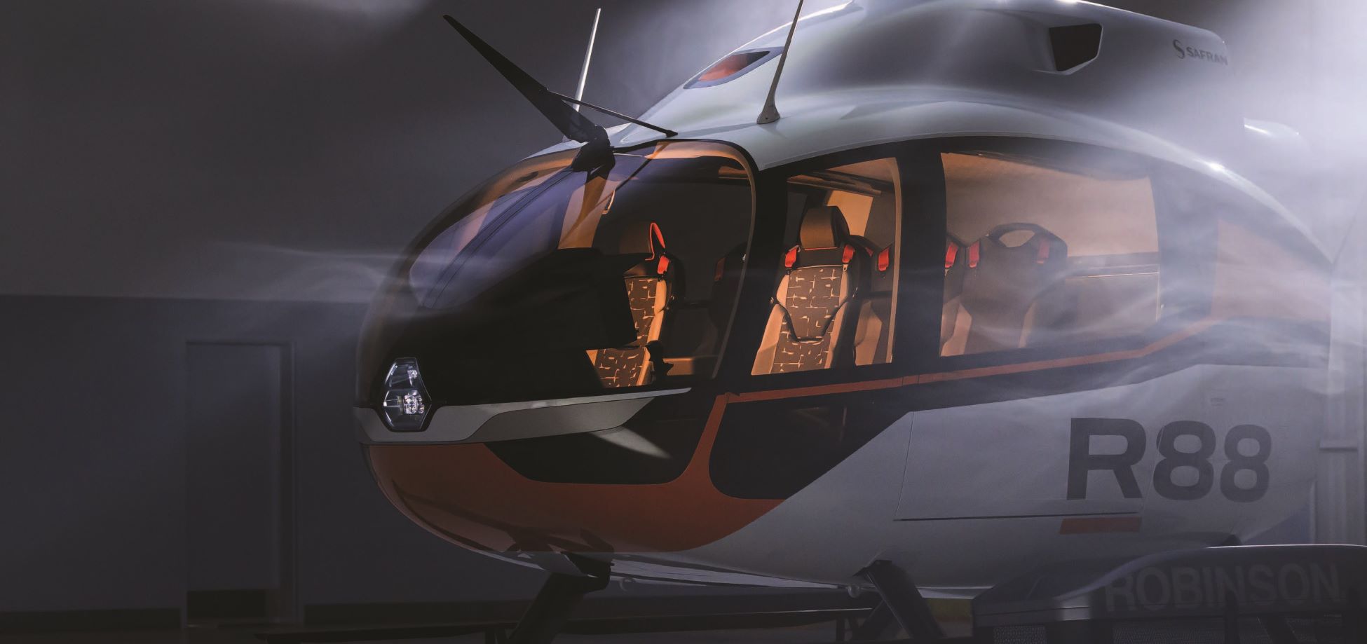
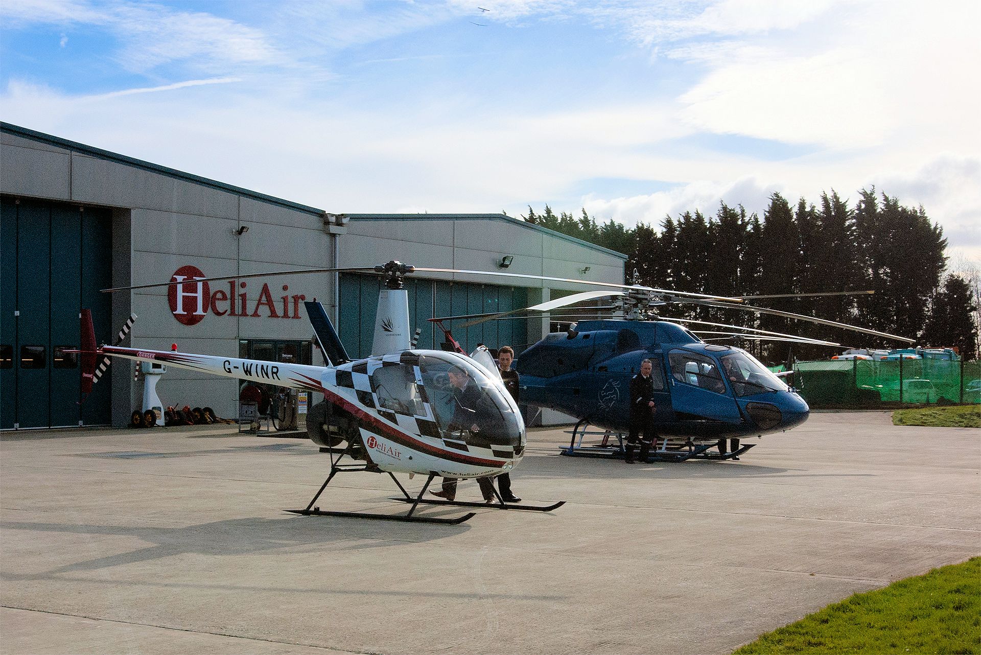
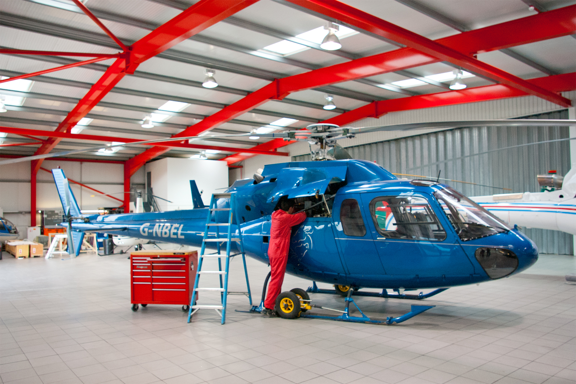
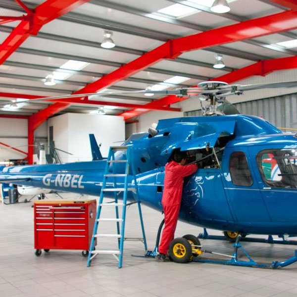
Heli Air provides the complete helicopter solution to its customers, focusing delivering the highest level of quality and value in all areas. Our unique ‘in house’ structure wraps our helicopter sales, training, engineering, charter and utility services into the complete helicopter solution for you.
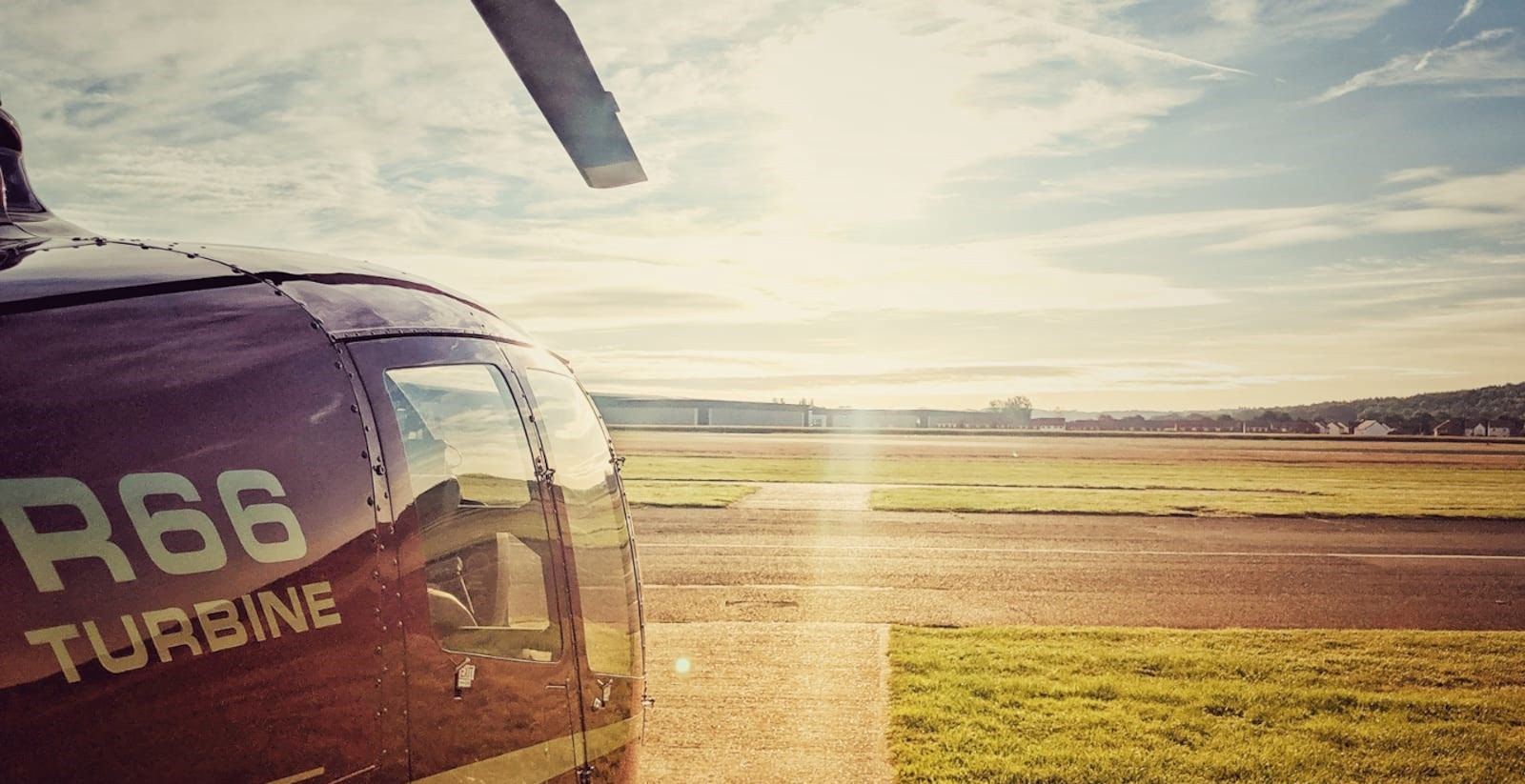
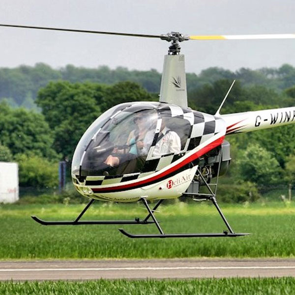
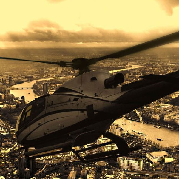
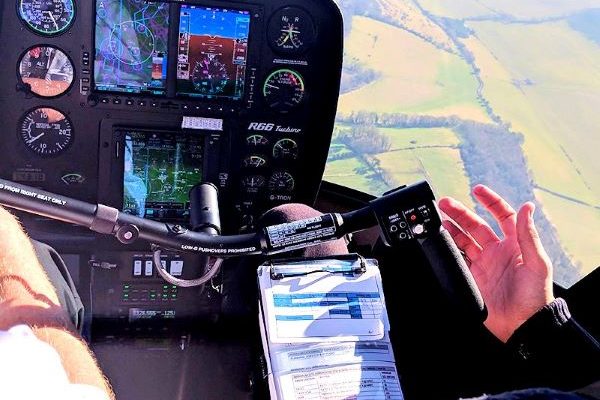
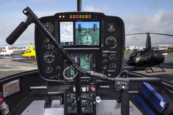
Headquartered at our own London airfield, Wycombe Air Park, Heli Air provides private helicopter pilot training, commercial helicopter flight training, new and used Robinson helicopters for sale, helicopter maintenance and spare parts, helicopter charter and more.
New: FE(H)澳洲5幸运官网结果168预测记录查询- 中国福彩澳洲5历史记录查询官网+五分彩结果直播 Examiner Seminar
Helicopter Flight Examiner (FEH) refresher seminars hosted and delivered by Heli Air’s experienced facilitators.
Specialising

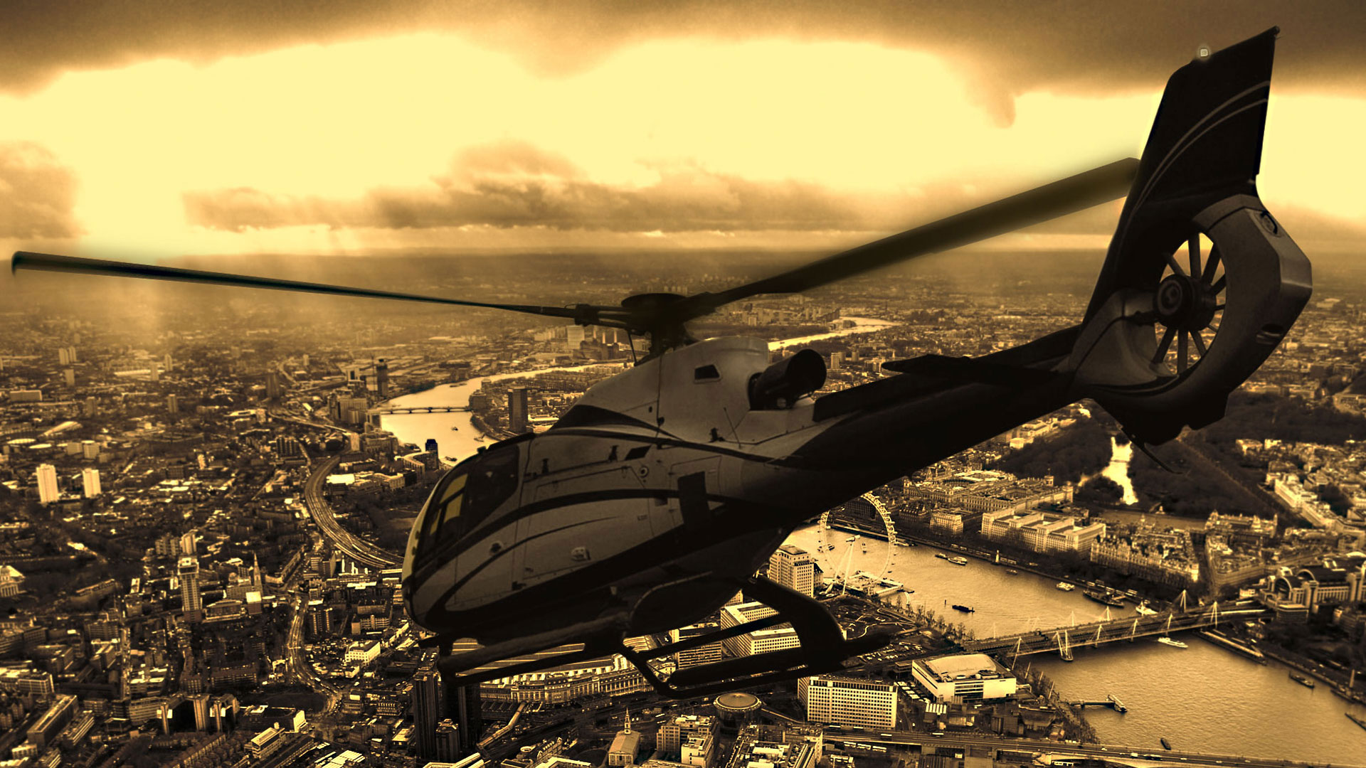
Buy Helicopter Experiences
News
Combine Helicopter Training with an Honours Degree
Heli Air work in partnership with Bucks New University providing a unique, helicopter and aviation degree programme. The BSc (Hons) degree allows you to gain your pilot’s licence whilst training towards hour honours degree. Get in touch for more information, and how training with Heli Air can enhance your helicopter career prospects.
Convenient Locations
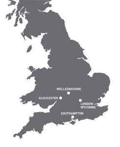
Heli Air’s services are available from various convenient locations, including near London from our own airfield, Wycombe Air Park. Get in touch to find out more.
You can also reach our head office on +44 (0) 1789 470476