FLUTTER OF A THREE-DIMENSIONAL WING
As a concrete example, let us consider an unswept cantilever wing with its root fixed in space while an airstream flows over it. We shall assume that the wing has an elastic axis that is a straight line, which is then chosen as the reference line for measuring the wing deflections. Assume that the wing deformation of each chordwise section can be described by three quantities: the bending (positive downward) of the elastic axis, the pitching (positive nose up) about the elastic axis, and the rotation (positive trailing edge down) of the aileron about the aileron hinge line. Let these
be denoted, for a section located at the spanwise coordinate y, and at time t, by h{y, t), a(y, t), fly, t), respectively. A complete description of the arbitrary functions fly, t), <x(y, t), and fly, t) requires a complete set of generalized coordinates. As is usual in the vibration analysis, however, let us choose a few, say three, generalized coordinates as representative of the fluttering wing. As an example, let
![]() КУ, t) = flt) fly) fly, t) = flt) ф{у) fly, t) = flt)g(y)
КУ, t) = flt) fly) fly, t) = flt) ф{у) fly, t) = flt)g(y)
where flt), a(/), and Д(г) are unknown functions of time, whereas f(y), ф(у), g(y) are three assumed functions of y. By fixing fly), ф(у), g(y), the deformation pattern of the wing is restricted.*
If Ay)> ФІУ)> g(y) were suitably chosen, a good approximation of the true flutter speed can be obtained. These functions are termed semirigid modes of deformation, or simply modes, on the basis of which the generalized coordinates flt), a(/), flt) are defined. We shall assume that the functions flt), v.(/), flt) have the dimensions of h, a, and fl respectively, so that f(y), ф(у), g(y) are nondimensional functions.
Generally, the functions fly), ф(у), and g(y) may be chosen as the uncoupled modes of free vibrations of the wing. f For ease of computation, they may also be chosen as polynomials or other elementary functions approximating the uncoupled vibration modes. The boundary conditions specifying the end constraints must be satisfied. As examples, the
* Usually the control surface may be regarded as a rigid body, and g(y) can be taken as a constant. A sufficient condition for this is that the fundamental torsional frequency of the surface, with the control lever rigidly attached to the wing, shall be well above the flutter frequency (see Duncan7,25). This is one reason why the control lever should be located at, or near, the middle of the span of the control surface. For the same reason the balancing masses should be located near the control lever, or at least not far away from it.
t Better results can be obtained by using the normal modes of free vibration of the wing. For example, if the first three normal modes are represented by the columns
|
|
![]() Ky, t) = 94(0/1(2/) + 92(0/2(2/) + 9з(0/з(2/) «(2/, 0 = 9i(0 ‘МгО + 9г(0 Фг(у) + 9з(0 Фз(У) Р(У, 0 = 1i(<)gi(y) + 92(0^2(2/) + 9з(0^з(2/)
Ky, t) = 94(0/1(2/) + 92(0/2(2/) + 9з(0/з(2/) «(2/, 0 = 9i(0 ‘МгО + 9г(0 Фг(у) + 9з(0 Фз(У) Р(У, 0 = 1i(<)gi(y) + 92(0^2(2/) + 9з(0^з(2/)
where 9j(0, 9г(0, 9з(0 are generalized coordinates.
following sets of functions may give a fair representation of a cantilever wing with the root section fixed in space:
![]() (2)
(2)
f(y), Ф(у) given by Eqs. 11 and 12 of § 6.4, g(y) = 1 (3)
If more than three generalized coordinates were taken, we have lengthier expressions. Thus, instead of Eqs. 1 we may write
Ky, t) = K(t)A(y) + h2(t)fM + • • • + hn(t)fn(y) (4)
etc., where fx(y), • • •,fn{y) are modes, on the basis of which the generalized coordinates h^t), ■ ■ •, hn(t) are defined. A comparison of the flutter speed obtained by using n generalized coordinates with that obtained by using n – f 1 generalized coordinates will give some indication of the degree of accuracy achieved. A rigorous proof of convergence by successively increasing the number of degrees of freedom, however, is rarely undertaken.
Let us take Eqs. 1 as an explicit example for the application of the method of generalized coordinates. Let m(y), Ia{y), Sa(y), Ip(y), S^(y), b(y), Cj)(y), and ah(y) be the mass per unit length, moment of inertia per unit length, etc., at the spanwise station y, corresponding to the same symbols used in § 6.10 (p. 223). We can write the kinetic energy per unit span for a section at у as
T'(y) = m{y) hii) + ШУ) *Ку) + Ш ky) КУ)
+ ‘S’a(y) %) %) + {Sp(y)[cf,(y) – ah(y)]b(y) + Tp(y)} fi(y) %) (5)
Substituting h, a, /3 from Eqs. 1 and integrating with respect to у over the wing span, we obtain the total kinetic energy of the wing:
t = mK + + де + 8$ + sM + pjtf (6)
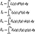
m = f m(y)P(y) dy
|
Pap =| {РрШсрІУ) ~ b(y) + K(y)s 4>(y)g(y) dy
The symbol / denotes the semispan of the wing, and 1Ъ /2 denote, respectively, the spanwise locations of the inner and outer ends of the aileron. m, Ia, etc., are called the generalized mass, generalized mass moment of inertia, etc.
The strain energy stored in the wing is
|
The Lagrange’s equations of motion are d (3T ЭК dt Эqj + dqt * |
|
Using Eqs. 6 and 13, we obtain the equations of motion: m h + BJi + Sp(i + mcofh = Qh BXR + /хЙ + Papfi + 7«W«2* = Qa Bp h + Pxpoi + Ір’/І + Ip<op2fi = Qp |
![]()
 |
|
 |
|
|
|
|
|
|
|
|
|
|
|
|
|
|
|
|
|
|
![]()
![]()
![]()
At the critical flutter condition, the wing motion is simple harmonic. We may write, in complex representation, (§ 1.8)
h{t) = h^ ЦІ) = /3(0 – (15)
Such a simple-harmonic solution is possible if we assume that the amplitude of oscillation is very small, because then the generalized forces Qh, Qa, Qp are linear functions of ft, a, /3, and Eqs. 14 become a system of linear equations. A solution of the form of Eqs. 15, with h0, a0, /?0 complex valued, is admissible for such a system of equations. When we substitute Eqs. 15 into Eqs. 14 and canceling the factor еш, the time-free equations of motion are obtained. If, in these equations, the elastic-
restoring-force terms are multiplied by factors of the form (1 + ig) to
represent the structural damping forces, in phase with the velocity and opposing the motion (see § 6.9), we obtain
— mmh + Д*a + 8ф) – f (1 + ig^rrtmff = Qh
— <x>Sji + 7aa + Дхд/З) + (1 + igffojfd. = Qol (16)
— m2(Sph + Дцз& + їф) + (1 + igp)Ipa>p2fi — Qp
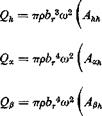
The generalized forces Qh, Qx, Qfl must be computed. The aerodynamic forces and moments at a section at у are given by Eqs. 15 of §6.10. For a three-dimensional wing, however, the coefficients Lh, La, Mh, Ma, etc., are not only functions of the Mach number M and the reduced frequency k, but also of the aspect ratio of the wing, the wing geometry (taper ratio, sweep angle, etc.), the wing deflection mode (the nodal-line location and the shape of the deflection curve), as well as the spanwise location y. To simplify the calculation, the strip assumption is often introduced, which states that the aerodynamic force acting at any section is the same as if that section were a part of a two-dimensional wing. Furthermore, the induced downwash due to trailing vortices is neglected. Therefore, the coefficients Lh, La, etc., are given by the same tables as those for the two-dimensional case.
Since к = ab/U is proportional to the semichord b, it generally varies across the span. If a particular cross section of the wing is defined as a reference cross section, of which the semichord and the corresponding “reference” reduced frequency are denoted by br and kr — mbfU, respectively, then any other cross section with a chord b(y) will have the reduced frequency
|
|
The coefficients Ьъ, Lx, etc., being functions of k, can thereafter be comprehended as functions of y, with the reference reduced frequency kr as a parameter.
The generalized force Qh for the oscillating bending motion is obtained by considering the virtual work due to a variation of the generalized coordinate 8h, which corresponds to a virtual displacement 8hf(y). This gives*
Q„(t)bh = – J’le. a.fy, t)8hf(y)dy
i. e.,
Qi,(t) = – f LKJ1(y, t)f(y)dy (17)
J 0
Similarly,
Qa(t) = J Мея(у, t) ф{у) dy, Qp(t) = ТшреІУ, t)g(y) dy (18)
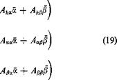
Substituting Eqs. 15 of § 6.10 into the above equations, we obtain

 R
R
* In Eq. 7 of § 1.6, the generalized coordinate qn and the generalized force Q„ are real valued; then the virtual work 6W is simply S Q„8q„ If the motion q„ is sinusoidal, Q„ is also sinusoidal, and qn, Q„ can be represented by complex representations. As is shown in Eq. 5a of § 5.4, a simple multiplication Q„ 6qn does not represent the virtual work. However, it is readily shown (Nilsson and Langefors7-50) that the sum of the product of Qn with the complex conjugate of 6q„
SfV 8q*n
represents a complex invariant with respect to coordinate transformation from the physical (real) coordinates to the generalized coordinates. The real and imaginary parts of &Wcan be interpreted physically as the “active” and “reactive” energy.
Let qn = q„oeimt, where qn0 is a real number, and Qn = (QnR + iQni)el°d then
8W= (S„r + гQ„i) ■ 6qn0
This equation can be used to compute the proper form of the generalized force Q„, since the complex invariant 6 W can be calculated in the rectangular Cartesian coordinates. Equations 17 and 18 are based on this argument.
where br is the semichord at a reference section, and
Ahh = Jo (j) Piy) Lh(y) dy A* =Jo f(y) ф(у) [-£» ~ (^ + dy An =| (j) f(y)g(y) An ~ A ~ e?)Lz] dy Ah = Jo f{y) m Mh ~ dy
A« =£(^-)4 ФЧУ) Ma – (I + efc) (A + Mh)
+ A dy
![]() An =| ^ Ф(у) g(y) мр – (^ + Lp – (cp – ep)Mz
An =| ^ Ф(у) g(y) мр – (^ + Lp – (cp – ep)Mz
+ (cp – ep) [X – + Lzj dy
|
(J+ e*) (Cfi ~ |
Ah =f’(^)3/(2/) g(y)[Th – {Cp – ep)Ph] dy Aa =| Ф(У) g(y) A – (cp – ep)PX — Q-+ a)j Th
Combining Eqs. 16 and 19, we obtain the equations of motion at the critical flutter condition. Comparing these equations with Eqs. 19 of § 6.10, we see that they are of the same form, except that the mass, moment of inertia, and aerodynamic coefficients must all be interpreted as the generalized quantities. The solution of the final determinantal equation can be obtained by the same methods used in § 6.11.
We have assumed in the above analysis (1) the existence of an unswept straight elastic axis, and (2) the strip assumption for aerodynamic action. Let us consider now cases in which these assumptions must be relaxed.
If the structure does not behave like a simple beam (in the sense that the formulas listed in § 1.1 hold), but its chordwise sections can be regarded as rigid, then the simplest procedure is to choose any convenient straight line as a reference line; the vertical deflection of a point on this line may be denoted by h, and the rotations of a cross section normal to the reference line in its own plane may be denoted by a. The expressions of the kinetic energy T and the generalized forces Qh, Qa, etc., take the same form as those presented above, except that the word “elastic axis” must now be interpreted as the “reference line.” The strain energy, however, cannot be obtained from Eq. 8 or 13, whose validity depends on the concepts of shear center and elastic axis. Nevertheless, from the general principles of elasticity, we can conclude that the strain energy must be expressible as a quadratic function of elastic displacements. (By Castigliano’s theorem the elastic displacements are linearly proportional to the loading only if the strain energy expression is quadratic.) In the present case, the strain energy is a quadratic function of h, a, and /5. A practical way of deriving such a strain energy expression is to use the stiffness influence coefficients, as shown in Eq. 7 of § 1.4.
For a monocoque wing with cutouts or with restrained cross-sectional warping, it is necessary to solve the shear lag problem in order to obtain the “flexibility” influence coefficients, from which the stiffness influence coefficients can be derived by a matrix inversion. If a structure is available for testing, the influence coefficients can be measured directly. The use of stiffness influence coefficients avoids differentiation of the assumed semirigid modes in computing the strain energy, and thus is favorable for numerical accuracy.
If the chordwise sections cannot be regarded as rigid, the deflection surface must be described by a continuous function in more than one dimension. For example, if a wing occupies a region on the (x, y) plane, the deflection w(x, y; t) may be expressed as
w(x, y, t)= q{t)f(x, y) + q2(t)f2(x, «/) + •••+ qn(t)fn(x, y)
where fx(x, y), f2(x, y), etc., are the modes on which the generalized coordinates qx, q2, ■ ■ •, etc., are defined. The calculation of the kinetic energy presents no difficulty. The strain energy can be expressed in terms of stiffness-influence coefficients. The aerodynamic force, however, would have to be calculated from the general theory of oscillating airfoils.
When the strip assumption for aerodynamic action is relaxed, it is necessary to solve the three-dimensional oscillating-airfoil problem for the oscillation mode of each generalized coordinate. This can be done in principle, but so far no convenient table of aerodynamic coefficients
exists. For low-aspect ratio wings, the wing-fuselage interference effect can also become important.
It is evident that in all cases Lagrange’s equations reduce to a set of linear equations in the generalized coordinates, and the methods of § 6.11 are sufficient to derive the flutter conditions.


