Our heavyweight helicopter equal in the world does not have
In Rostov started production of the most load-lifting rotary-wing car The Russian holding «Helicopt[...]

Everything about aircrafts and helicopters. News and events in aviation worldwide. Civil, transportation, military helicopters and airplanes.

Everything about aircrafts and helicopters. News and events in aviation worldwide. Civil, transportation, military helicopters and airplanes.

Everything about aircrafts and helicopters. News and events in aviation worldwide. Civil, transportation, military helicopters and airplanes.

Everything about aircrafts and helicopters. News and events in aviation worldwide. Civil, transportation, military helicopters and airplanes.


The effects of turbulence on the reading of a static tube are complex. In the case of isotropic turbulence, it is estimated that the reading error is 1% when the intensity of turbulence is 10%. There are difficulties only in the zones of separation and wakes.
2.4.2 Effect of size and shape of holes
Each hole in a wall alters the boundary conditions producing a curvature of the streamlines and hence a pressure change, these effects decrease with the decreasing size of the holes. Usually the streamlines entering the
Influence of size and shape of holes on pressure readings
hole raise the pressure. In some cases the separation of the stream on the leading edge of the hole causes a decrease in pressure.
The size of the holes of static pressure must therefore be the smallest possible (see Figure 2.17, which also indicates the effect of the shape of the hole) but this is not consistent with the need not to increase excessively the inertia of the system static hole-connection pipe-pressure gage.
Typical diameters of holes in experiments at low speeds are 0.5-1 mm; in the experiments at higher speed, the size of the hole is usually chosen as the smallest that can be achieved with a power drill, e. g. 0.02 mm.
By increasing the Mach number of the undisturbed stream, a critical value is reached (Mcr = 0.7) for which M > 1 is generated on the tube, and upstream of the holes the first shock waves change the static pressure; with the growing Mach number the supersonic zone extends and the shock waves moving downstream step over the holes which are therefore in a supersonic flow. When this happens, reading the pressure becomes independent of the position of the support and the distribution of velocity on the front of the tube differs appreciably from that which occurs at low speeds.
Under these conditions, therefore, a static tube designed to operate at low speed can result in appreciable errors. This is illustrated in Figure 2.15 which shows the results obtained with a tube in which the phenomena are accentuated by the blunt shape of the head. By using tubes with a very slender head, a critical Mach number can be increased up to values close to 1.
At supersonic speeds, the head of the tube should be conical: the opening angle must be less than that for which a detached shock wave is
 |
Influence of compressibility on the readings of a blunt static probe at different angles of attack
 |
Effect of position of holes in a static pressure supersonic probe
formed and static holes should be placed at least ten diameters after the beginning of the cylindrical tube (Figure 2.16) where the effects of shock waves are offset by the expansion that occurs at the beginning of the cylinder.
The presence of a velocity gradient in a boundary layer does not involve a gradient of static pressure but the gradient of stagnation pressure produces a deviation of streamlines towards the lowest speed and then induces variations in the pressure read by the probe. A similar phenomenon occurs for the downwash on the support of the probe. The proximity of a wall increases the speed and decreases the pressure on one side of the probe; errors less than 1% in detecting the static pressure are made only if the probe is kept at a distance of at least 5 diameters from the wall.
Both phenomena actually discourage the use of static probes for measurements in the boundary layer: since static pressure is constant in the layer, it can be measured in a hole in the wall.
The measured pressure is appreciably influenced by the position of the taps with respect to the head and to the stem (Figure 2.13): downstream of the head an increase in speed will be generated with a consequent decrease in pressure, the presence of the stem introduces an error of the opposite sign. The position of the orifices should be chosen such that the error due to the presence of the head is approximately equal and opposite of that due to the stem. Using this technique, Prandtl made a very compact probe (Figure 2.12) where the taps were located at 2.9 D from the head (error = -1%), and 9.6 D from the stem (error = 1%). In a more reliable probe, built at NPL, the taps are positioned at 8 D from the head (error = – 0.5%) and 16 D from the stem (error = 0.5%).
2.4.1 Effects of non-alignment
If the static probe is not aligned with the direction of the velocity, there is a distortion of streamlines, or even separation with consequent
 |
Errors in static pressure due to the position of taps

 |
Influence of the angle of attack on the readings of a static probe
pressure changes. The influence of angle of attack on the reading of the static tube, as shown in Figure 2.14, is larger than that for the Pitot tube (Figure 2.4). To reduce the effects of the angle of attack, from 4 to 8 orifices are drilled, depending on the pipe diameter, distributed on a circle: the presence of several orifices causing flows inside the tube tends to average in some way the values read by the various orifices.
The local static pressure, equal to that prevailing outside the boundary layer, can be measured in an orifice on the surface of a body immersed in a stream. If, in particular, the static pressure of undisturbed stream, pm, is to be measured, an orifice can be drilled where, from a theoretical point of view, the pressure reaches this value, e. g. in the presence of the boundary layer (Figure 2.2) on a cylinder of circular cross-section in the locations at ±35°. Small deviations from these points, however, lead to large changes in pressure, so, as in the case of stagnation pressure, the use of slender bodies, like tubes, which introduce small disturbances in the stream, is preferred.
The basic concept is that in the absence of curvature of streamlines there is not a centrifugal force to be balanced with a gradient of pressure: keeping streamlines straight equals cancelling the variation in pressure normal to the streamlines themselves. Strictly speaking, only on a flat plate pm could be measured through orifices on the surface because any body disturbs the stream: in practice, a slim body can be used if the pressure is read in a position where the initial disturbances are sufficiently damped and streamlines are straight and parallel to the main flow.
The instrument used, designed by Prandtl, consists of a thin tube aligned with the stream with a closed-end upstream, and backed by a stem perpendicular to it (Figure 2.12). The pressure is detected in a number of orifices in the pipe wall.
 |
Static pressure probes: top, the Prandtl tube; bottom, the NPL tube
Assuming that the motion is nearly steady and that the lateral components of turbulence are so low that they have a negligible effect on the angle of incidence, the resulting velocity U equals the sum of the average speed, U, and the fluctuating component u: the Pitot tube then reads
If velocity is constant in value but varies widely in direction, it is expected that the tube will detect a pressure lower than real because, for angles other than zero, the measured pressure is less than the stagnation pressure.
The current state of knowledge is very unsatisfactory, particularly as regards the use of Pitot tube in jets with strong turbulence, but it is hard to believe that a simple formula can give the corrections to be made to measurements in turbulent flows without knowledge of extensive data on the turbulence itself; if measures of turbulence are needed as primary data, they must be obtained with a hot wire or a laser-Doppler or a 2-focus laser anemometer.
For Reynolds numbers lower than 1000 (based on the diameter of the orifice), corrections are required due to the presence of a completely viscous flow; Figure 2.11 shows the calibration curve for very low Reynolds numbers. For Reynolds numbers less than 50, the error increases rapidly and the curve tends to become
pOI _ p = 1 + 112
q Red
Such small values of the Reynolds number are typical of measurements made in the boundary layer, where speeds are low (down to zero) and
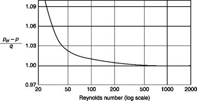 |
Effects of low Reynolds numbers on the readings of a Pitot tube (d/D = 0.64)
Pitot tubes are very small to avoid both the displacement of the virtual centre in the presence of velocity gradients and the effects of proximity to the wall.
For a probe perfectly aligned with the stream, the reading is independent of the Mach number up to Mach numbers close to 1 (Figure 2.10). At supersonic speeds in front of the tube, a detached shock wave is generated, which is locally normal to the axis of the tube, so that the pressure detected by the Pitot tube is the stagnation pressure downstream of a
normal shock wave. The measured pressure (subscript 2) can be used to calculate the Mach number of the stream (M1 > 1), if the stagnation pressure upstream of the shock wave (subscript 1) is known, through the equation, known as the Rayleigh formula:
Y 1
![]()
![]()
 |
(Y – 1)Mi + 2 Y-1 ( 2y M2 – Y-1 Y-1
(y + 1)Mj2 lr +1 1 Y + 1J
The stagnation pressure upstream of the shock wave must be measured independently, as the pressure in the stagnation chamber that feeds the de Laval nozzle that generated the supersonic stream.
The Mach number can also be calculated, if the static pressure upstream
![]()
 |
Effects of the Mach number on the readings of a Pitot tube with a hemispherical head (d/D = 0.3)
of the shock wave is known, by Equation (2.6) obtained by dividing Equation (2.5) by Equation (2.1):
Y 1
![]()
![]() ___ 2___ Y-1 (JY_ M2 _ Y-1Y-1
___ 2___ Y-1 (JY_ M2 _ Y-1Y-1
(y + 1)M Iy + 1 Y + 1)
The static pressure upstream of the shock wave can be measured on a wall at the entrance of the test chamber.
The correction to the reading of a Pitot tube placed near a wall are less immediate than the corrections for the gradient of stagnation pressure since the error depends on the whole speed profile between the tube and the wall. A process of successive approximations could be developed to deduce the true profile from the profile measured but this procedure would require a large amount of experimental work. As said above, for
![]()
 |
Pitot probes for boundary layer
measurements in thin boundary layers very small tubes are used for which the correction for the effect of proximity to a wall can be ignored; for cylindrical tubes the effect tends to zero at distances greater than 2 diameters from the wall (Figure 2.9); the correction for a flattened tube is more uncertain since the effect of the wall is to prevent the deviation of the streamlines induced by the presence of the Pitot tube and a flattened tube deforms the streamlines more than a circular pipe.
In a viscous layer, the variation of speed, and hence of stagnation pressure, along the opening of the tube causes two effects:
■ first, the tube senses the average of the squared speed that is greater than the square of the speed on the axis of the tube;
■ second, the deviation of the stream towards the region of lower stagnation pressure brings down the streamlines with a stagnation pressure higher than that corresponding to the axis of the tube.
 |
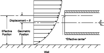
The experimental results show that the pressure detected by a Pitot tube is equal to the pressure existing at a stagnation point moved about
Displacement of the effective center of the Pitot tube in the presence of a shear layer
|
|
0.18 d from the axis of the tube in the direction of increasing speed (Figure 2.7).
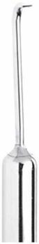
For this reason, to perform measurements in the boundary layer or other viscous layers (the stagnation pressure in many flows is constant outside these layers), appropriate Pitot tubes available on the market (Figure 2.8) are used, ending with very small tubes (with a diameter of 0.6 mm with the end flattened) to minimize both the effect of shifting the “effective center” and the effect of proximity of a solid wall. Probes for the boundary layer can easily be made in the laboratory from suitably truncated hypodermic tubes, bent at 90° and made flat.
Flattened tubes are very sensitive to the angle of incidence and are not suitable for use in highly turbulent flows because of the considerable delay (of the order of seconds) that they introduce in the transmission of pressure signals.