Our heavyweight helicopter equal in the world does not have
In Rostov started production of the most load-lifting rotary-wing car The Russian holding «Helicopt[...]

Everything about aircrafts and helicopters. News and events in aviation worldwide. Civil, transportation, military helicopters and airplanes.

Everything about aircrafts and helicopters. News and events in aviation worldwide. Civil, transportation, military helicopters and airplanes.

Everything about aircrafts and helicopters. News and events in aviation worldwide. Civil, transportation, military helicopters and airplanes.

Everything about aircrafts and helicopters. News and events in aviation worldwide. Civil, transportation, military helicopters and airplanes.


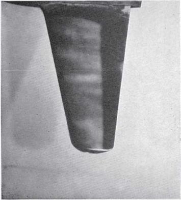
In high speed wind tunnels, the china clay method has been replaced by methods based on the sublimation of a solid. The sublimating solid is diluted in a spraying solution in a highly volatile liquid that evaporates before the test. In continuous supersonic tunnels, a solid is used with a slow sublimation rate such as azobenzene; in intermittent supersonic wind tunnels, a solid with a fast sublimating rate like exachloroethane is used. In subsonic and transonic wind tunnels, solids with an average rate of sublimation like acenaphthene are widely used. Suitable solvents are benzene and xylene. The method has the disadvantage of providing images with a poor contrast (Figure 6.13).
![]() Boundary layer transition visualized with a sublimating material
Boundary layer transition visualized with a sublimating material
Transition
I
 |
Laminar Flow Turbulent Flow
This is the most effective evaporative method, developed at the National Physics Laboratory in the UK during the Second World War: the model is sprayed with a transparent cellulose adhesive containing suspended powdered kaolin (china clay); when the glue is dry, the model surface is accurately smoothed and becomes permanently white. If a liquid with a similar refractive index is sprayed onto the kaolin (with refractive index n = 1.56), the refraction of light in crystals that make up the layer is inhibited and the layer is therefore transparent. Turbulent zones, where the evaporation of the liquid is increased, turn white faster than the laminar zones (Figure 6.12). The choice of liquid is made according to its evaporation rate and the speed of the tunnel: at low speeds, methyl ethyl
 |
Boundary layer transition visualized with the china clay method
salicylate (n = 1.56) was successfully used; for speeds of few m/s, acetone was also used. As mentioned, the coverage of the model with the kaolin is permanent and can be used repeatedly for different tests.
 |
The use of a film of a non-volatile liquid is based on the principle that the film moves in the direction of the tangential stresses acting on the model.
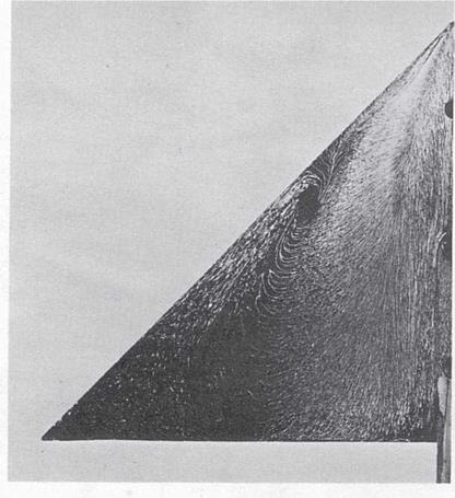
The technique is particularly suitable in visualizing surface streamlines (Figure 6.9) and flow separation (Figure 6.10). The transition can be detected as the surface stresses may be able to remove the fluid in the turbulent zone, while the laminar zone remains wet (Figure 6.11). Alternatively, before the liquid is swept away by the turbulent region, a difference can be observed in the shape of the waves on the surface of the liquid with respect to those formed in the laminar region: the wavelength is greater in the turbulent region. The latter method can be used in tests of short duration in intermittent tunnels.
The viscosity of the liquid should be chosen as a function of the speed of the tunnel and the duration of the test: the maximum viscosity is
Streamlines on a delta wing visualized with an oil film (lampblack + kerosene)
|
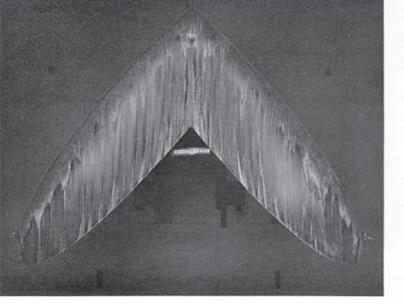
Flow separation on a sweptback wing of an orbiter model visualized with an oil film
Boundary layer transition on a double delta wing visualized with oil and titanium dioxide
|
required in tests in continuous supersonic wind tunnels. At low speeds wind tunnels are most suitable, in order of increasing viscosity: kerosene, light diesel oil, light oil for transformers. In high speed wind tunnels, often the static pressure in the test chamber is so low that liquids with high vapor pressure tend to evaporate; in these cases, oil for vacuum pumps must be used. In cryogenic wind tunnels, liquids with a low freezing point such as propane must be used.
The heavy mineral oils suitable for high speed wind tunnels are naturally fluorescent and can therefore be observed with a good contrast illuminating them with ultraviolet lamps; lighter oils can be made more observable using fluorescent additives.
An alternative is the addition of pigments: lampblack on clear models, white pigments such as titanium dioxide (Figure 6.11) or kaolin on dark models. An additive, e. g. oleic acid to titanium dioxide, is usually used to control the flocculation of the paint. One advantage in using the oil— lampblack mixture is the fact that it can be stored in bottles for an indefinite time. The mixture of titanium dioxide or kaolin and oil is instead a real paint: it tends to dry in the air and therefore it must be prepared just in time for each test.
To avoid the parallax error that would be made if photographing curved surfaces, the model can be covered with a self-adhesive plastic – coated white paper on which the oil-lampblack mixture is applied; after the test, the paper is removed and made plane before photographing. Alternatively, on completion of the test, the produced pattern is removed with a transparent adhesive sheet that is then photographed and possibly stored for later analysis.
If a difference of potential is applied between a metallic wire immersed in a stream of water and a metal plate on the bottom of the channel, by
|
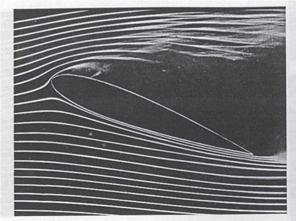
Stall of an airfoil visualized with smoke filaments
|
electrolysis of water from the wire, a continuous stream of bubbles of hydrogen or oxygen is generated, depending on the sign of the difference of potential applied. It is preferred that the wire is the cathode since the amount of bubbles of hydrogen produced is twice that of oxygen. Wires with a diameter of the order of hundredths of millimeters are used so that the bubbles, which have a size comparable to the diameter of the wire, do not rise too quickly to the surface. Adding an electrolyte to water is not strictly needed because the usual presence of salts dissolved in tap water is sufficient; anyway sodium chloride or sodium sulfate can be added to water. The applied voltages are 100-200 V.
If the cathode is a thin wire normal to the direction of the stream and a short electrical pulse is applied, a line of hydrogen bubbles is generated along the wire (Figure 6.7).
With a power supply pulsed with a constant frequency, successive lines of bubbles are obtained separated by a constant time interval (time lines). These lines are carried by the stream and deform according to the profiles of local speed.
Also, if the wire is partially covered with an insulating varnish, emission of bubble packs can be achieved which provide an indication of the speed profiles in the stream (Figure 6.8). The time period during which the
 |
Time lines generated with hydrogen bubbles
bubbles survive in the stream is limited. The spread of bubbles increases with the Reynolds number and is very rapid in turbulent flow. The application of the method is therefore limited to very slow streams, with speeds of the order of 20-30 cms-1.
The smoke consists of a suspension of solid and/or liquid particles in a gas. The required characteristics of smoke in wind tunnel applications are:
■ must not form deposits on the model or in the pipes that lead to the injectors;
■ must have a density similar to that of air: in this way, the effect of buoyancy is null;
■ must be clearly visible, non-poisonous, and non-corrosive;
■ must be inexpensive, easily produced and controllable.
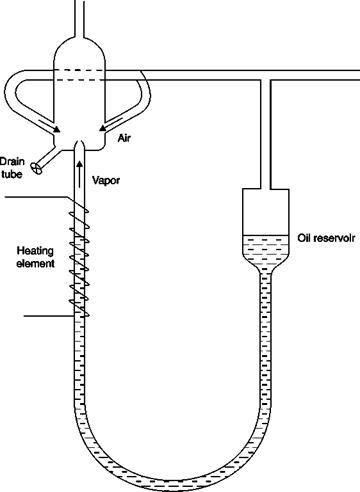
The most common methods used to produce smoke are based on the combustion of organic materials or the evaporation of a liquid. Combustion involves long preparation time and the production of solid particles forming deposits. The preferred option is the evaporation of mineral oil (e. g. kerosene) that is heated by the Joule effect in an apparatus designed by Preston and Sweeting (Figure 6.4), which is operational in
A mineral oil vapor generator
|
Mist of ▲ condensed vapor droplets
|
about 5 minutes. The adjustment of the flow of smoke to be sent to the injector is achieved by regulating the flow of air that feeds the apparatus. Sometimes the air supply is drawn from the stream in order to obtain the automatic adjustment of the injection rate of smoke to the varying speed of the stream.
The main problem presented by the technique of injecting a thread of smoke or vapor into a stream of air, or ink in a stream of water, is the
 |
need not to disturb the flow. On the other hand, if well-defined filaments are needed, it is necessary that the injection speed be equal to that of the stream and at the same time that the wake produced by the injector not be turbulent. The latter requirement limits the applicability of the method at very low speeds in order to keep the Reynolds number of the injector below the critical value.
In air, the technique is used in special smoke tunnels, used for pedagogical purposes (Figure 6.5): to obtain a good contrast with the smoke filaments, one of the side walls of the test chamber is black and a system of lamps illuminates the model from above and from below. The streamlines on a stalled airfoil visualized with this technique are reported in Figure 6.6. In this case, the smoke is injected through a comb of injectors upstream of the test chamber.
Many basic aerodynamic experiments were conducted by Prandtl and co-workers by moving the models in tanks containing water. Very fine particles of aluminum or coffee or lycopodium may be used to visualize streamlines, separation of boundary layer and eddies that are generated on the model partly submerged in the liquid. The vortices that are generated downstream of a cylinder moving in a liquid, photographed with a long exposure, are shown in Figure 6.3.
 |
Vortices downstream of a cylinder visualized with aluminum powder
6.1.1 Wool or silk tufts
Wool, silk or nylon tufts 5 f 15 mm long are glued at one end on the surface of the model and the other end is left free. If the position of the tufts has to be often changed, scotch tape can be used to fix the tufts to the model. The presence of the tufts can be a trigger for a premature transition so the tufts should be placed gradually from the trailing edge, checking whether the inclusion of new rows of tufts affects the downstream conditions.
 |
|
If the tufts are short enough not to interfere with the external field, it is easy to interpret their behavior: the presence of a turbulent boundary layer is highlighted by a lively movement of the tufts, the separation of the boundary layer is highlighted by the tendency of the tufts to move violently and to rise from the wall pointing upstream (Figure 6.1 b).
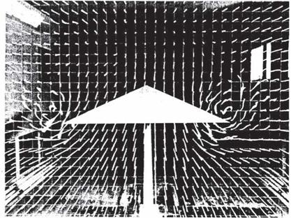
Vortices downstream of a delta wing visualized with tufts mounted on a grid across the test chamber
|
Source: NASA |
In order to visualize the external flow, the tufts must be supported by a grid perpendicular to the stream: in Figure 6.2, the free vortices downstream of a delta wing at incidence are shown.
The density variations in a fluid can be visualized using the optical methods (shadowgraph, Schlieren and interferometry), which highlight the changes in the refractive index of the fluid. These methods furthermore allow measurements of density (especially interferometry). These optical methods, besides being non-intrusive and giving a global view of the flow field, as do all methods of visualization, have peculiar advantages and disadvantages:
■ The inertia of the system is practically zero, the study of unsteady motions is possible with the temporal discrimination allowed by the speed of the shut-off system (camera, video camera). This feature is particularly useful in supersonic wind tunnels and even more in hypersonic ones in which the duration of the tests is very short.
■ Optical methods are able not only to visualize streams at Mach numbers lower than those considered typical of compressible aerodynamics, but can also visualize changes in fluid density due to heat transfer or mass diffusion.
■ All optical methods give the value of the density variations integrated along the optical path; increasing difficulties are encountered in
interpreting the images going from two-dimensional plane fields to axially symmetric fields and to three-dimensional fields.
■ Limits on these methods are low density hypersonic motions and low density gradients.
Apart from the study of laminar profiles, the main reason for the interest in knowledge of the transition is in monitoring the effectiveness of transition strips. Diffusive flows of mass, momentum and energy in the boundary layer increase more or less abruptly in the transition from the laminar to the turbulent regime.
In the zones of separation tangential stresses (diffusive flows of momentum) decrease to zero and become negative.
■ The variations in tangential stresses can be highlighted by covering the body with a film of non-volatile liquid.
■ The different diffusion of mass in laminar and turbulent zones may be shown by making use of the sublimation of a solid, such as naphthalene, or the evaporation of a liquid, as in the china clay method.
■ The different diffusion of energy can be highlighted with heat-sensitive coatings.
In three-dimensional flows, streamlines near a solid surface can be very different from those of the external stream. Surface streamlines can also be very complicated in the zone of the boundary layer, separation and near obstacles on the surface and below a vortex.
Particles or wool tufts can be used as for the external stream but it is much more appropriate to spread a non-volatile liquid (oil), possibly with the addition of dyes, on the surface: oil moves under the action of tangential stresses and then in the direction of streamlines that appear as streaks in the oil film.