Category Aerodynamics for Engineering Students

Aerofoil section made up of unequal circular arcs

A convenient aerofoil section to consider as a first example is the biconvex aerofoil used by Stanton* in some early work on aerofoils at speeds near the speed of sound. In his experimental work he used a conventional, i. e. round-nosed, aerofoil (RAF 31a) in addition to the biconvex sharp-edged section at subsonic as well as supersonic speeds, but the only results used for comparison here will be those for the biconvex section at the supersonic speed M = 1.72.

Подпись: and
Aerofoil section made up of unequal circular arcs

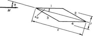
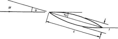
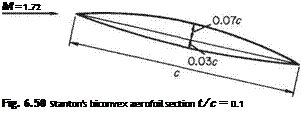
Example 6.11 Made up of two unequal circular arcs a profile has the dimensions shown in Fig. 6.50. The exercise here is to compare the values of lift, drag, moment and centre of pressure coefficients found by Stanton* with those predicted by Ackeret’s theory. From the geometric data given, the tangent angles at leading and trailing edges are 16° = 0.28 radians and 7° = 0.12 radians for upper and lower surfaces respectively. Then, measuring x from the leading edge, the local deflections from the free-stream direction are

Подпись: M = 1.72 Fig. 6.50 Stanton's biconvex aerofoil section t/c = 0.1

for upper and lower surfaces respectively.

Подпись: *T. E. Stanton, A high-speed wind channel for tests on aerofoils, ARCR and 1130,

Aerofoil section made up of unequal circular arcs

Aerofoil section made up of unequal circular arcs

Incidence degrees

0

2-5

5-0

7-5

CL

calculated

0

0-125

0-25

0-375

observed

-0-064

0-096

0-203

0-342

cD

calculated

0-044

0-0495

0-066

0-093

observed

0-052

0-054

0-070

0-093

—Cm

calculated

0-039

0-101

0-164

0-226

observed

-0-002

0-068

0-114

0-178

kcp

calculated

00

0-81

0-65

0-60

observed

0-03

0-69

0-54

0-49

LID

calculated

0

2-5

3-8

4-0

observed

-1-2

1-8

2-9

3-5

Fig. 6.51

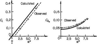
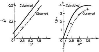
It will be noted again that the calculated and observed values are close in shape but the latter are lower in value, Fig. 6.51. The differences between theory and experiment are probably explained by the fact that viscous drag is neglected in the theory.

Symmetrical double wedge aerofoil in supersonic flow

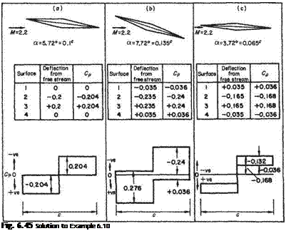
Example 6.10 Plot the pressure distribution over the symmetrical double-wedge, 10 per cent thick supersonic aerofoil shown in Fig. 6.44 when the Mach 2.2 flow meets the upper surface (a) tangentially; and (b) and (c) at incidence 2° above and below this. Estimate also the lift, drag, and pitching moment coefficients for these incidences.

The semi-wedge angle e0 = arc tan 0.1 = 5.72° = 0.1 radians

M = 2.2; M2 = 4.84; Vm2 – 1 = 1.96

Symmetrical double wedge aerofoil in supersonic flow

and for the incidence а = єо = 0.1°. Using Eqn (6.146), the distribution is completed in tabular and graphical forms in Fig. 6.45.

Подпись: Fig. 6.45 Solution to Example 6.10

For the lift drag and moment a more general approach can be adopted. If a chordwise element 6x, x from the leading edge be taken, the net force normal to the chord is

(Pl ~Pu)6x = (CpL – CpV)^pV26x

Total normal force = lift (since a is small)

L = CLl-pV2c = jcpL – Cpv)PV4x (6.148)

In this case Eqn (6.148) integrates to give

Clc 2 (Сй — Сй) + 2 —

and on substituting CP2 = 2e[VM2 — 1, etc.,

Cl = ~7m2 ^£з-£1+£4-£21 (6.149)

But for the present configuration

£l = £o — Є2 — —£o — &■> 63 = £o + £4 = —£0 + &

when Eqn (6.149) becomes

Symmetrical double wedge aerofoil in supersonic flow Подпись: (6.150)

CL = ^ [(є0 + a) – (є0 – a) + (-є0 + a) + (єо – a)]

In the present example

Силі = 0.132, Cl5.72 = 0.204, Cum = 0-275

The contribution to drag due to a chordwise element of lower surface, say, is

1 .

Pl£lSx = Cpl – pV2£L^x + po£LSx

where po is the free-stream static pressure which integrates to zero and may be neglected throughout. Again using Cpl = lEypjM2 — 1, the elemental contribution to drag becomes

Подпись: pV2Sx2ej 1

VM2 – l2f

The corresponding contribution from the upper surface is

Подпись: VM2 - 1 2^-~pV4x

Symmetrical double wedge aerofoil in supersonic flow Подпись: (6.151)

The total wave drag becomes

It is now seen that aerofoil thickness contributes to the wave drag, which is a minimum for a wing of zero thickness, i. e. a flat plate. Alternatively, for other than the flat plate, minimum wave drag occurs at zero incidence. This is generally true for symmetrical sections although the magnitude of the minimum wave drag varies. In the present example the required values are

Symmetrical double wedge aerofoil in supersonic flow Подпись: (6.152)

Сд,72 = 0.029, CDil2 = 0.0408, CDlll = 0.0573 Lift to wave drag ratio. Directly from Eqns (6.150), and (6.151):

Now LjD is a maximum when DjL = a 4- {tjc)2 fa is a minimum and this occurs when the two terms involved are numerically equal, i. e. in this case, when a = tjc. Substituting back gives the maximum LjD ratio as

t/c

>(-Г2©

For the present example, with tjc = 0.1, [Z,/D]max = 5 occurring at 5.72° of incidence, and

Подпись:= 4.8

M 7.72

Moment about the leading edge Directly from the lift case above, the force normal to the chord from an element Sx of chord x from the leading edge is (CPL — Cpu)^pV2Sx and this produces the negative increment of pitching moment

AM=-(CPL-CPu)x^pV26x

Integrating gives the total moment

-M = J‘(CPL – CPl])^pV2xdx = – CMl-pV4

Making the appropriate substitution for Cp:

which for the profile of the present example gives

-Cm = ^2 I Iа _ єо – (єо – x)] — + [(eo + a) + (a 4- e0)] j

Подпись: [2x]‘ VM2-!

Symmetrical double wedge aerofoil in supersonic flow Symmetrical double wedge aerofoil in supersonic flow

i. e.

and this is independent of Mach number and (for symmetrical sections) of incidence.

Symmetrical biconvex circular arc aerofoil in supersonic flow

While still dealing with symmetrical sections it is of use to consider another class of profile, i. e. one made up of biconvex circular arcs. Much early experimental work

Symmetrical double wedge aerofoil in supersonic flow

Fig. 6.46

was done on these sections both with symmetrical and cambered profiles and this is readily available to compare with the theory.

Подпись: -Pu Подпись: VM2-! Подпись: , і , 2x “ OL + £() ( 1 Подпись: (6.155)

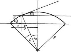
Consider the thin symmetrical aerofoil section shown in Fig. 6.46. On the upper surface x from the leading edge and the deflection of the flow from the free – stream direction is єи, and єи — —a + £o[l — (2x/c)],* so that the local pressure coefficient is

Symmetrical double wedge aerofoil in supersonic flow
Подпись: Fig. 6.47

6D =

Подпись: CD Подпись: v/M2- 1 Подпись: az+-

and integrating gives after substituting for Єу and

Symmetrical double wedge aerofoil in supersonic flow

Now, by geometry, and since єо is small, є0 = 2(t/c), giving

The lift/drag ratio is a maximum when, by division, D/L = a+ [^(t/c)2/a] is a minimum, and this occurs when

Подпись: 3 cJ a4 /t 21

Then

Подпись: a

Symmetrical double wedge aerofoil in supersonic flow Подпись: t/c

1 y/3 c 0.433

For a 10% thick section (L/D)mzx = 4at a = 6.5°

Moment coefficient and kcp

Подпись: M Symmetrical double wedge aerofoil in supersonic flow Подпись: (6.157)

Directly from previous work, i. e. taking the moment of 8L about the leading edge:

Symmetrical double wedge aerofoil in supersonic flow

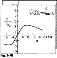
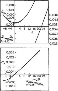
and the centre of pressure coefficient = -(См/Cl) = 0.5 as before. A series of results of tests on supersonic aerofoil sections published by A. Ferri[32] serve to compare with the theory. The set chosen here is for a symmetrical bi-convex aerofoil section of f/c = 0.1 set in an air flow of Mach number 2.13. The incidence was varied from — 10° to 28° and also plotted on the graphs of Fig. 6.48 are the theoretical values of Eqns (6.156) and (6.157).

Examination of Fig. 6.48 shows the close approximation of the theoretical values to the experimental results. The lift coefficient varies linearly with incidence but at some slightly smaller value than that predicted. No significant reduction in Cl, as is common at high incidences in low-speed tests, was found even with incidence >20°.

The measured drag values are all slightly higher than predicted which is under­standable since the theory accounts for wave drag only. The difference between the two may be attributed to skin-friction drag or, more generally, to the presence of viscosity and the behaviour of the boundary layer. It is unwise, however, to expect the excellent agreement of these particular results to extend to more general aerofoil sections – or indeed to other Mach numbers for the same section, as severe limitations on the use of the theory appear at extreme Mach numbers. Nevertheless, these and other published data amply justify the continued use of the theory.

General aerofoil section

Retaining the major assumptions of the theory that aerofoil sections must be slender and sharp-edged permits the overall aerodynamic properties to be assessed as the sum of contributions due to thickness, camber and incidence. From previous sections it is known that the local pressure at any point on the surface is due to the magnitude and sense of the angular deflection of the flow from the free-stream direction. This deflection in turn can be resolved into components arising from the separate geometric quantities of the section, i. e. from the thickness, camber and chord incidence.

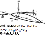
The principle is shown figuratively in the sketch, Fig. 6.49, where the pressure p acting on the aerofoil at a point where the flow deflection from the free stream is є may be considered as the sum ofpt +pc+ pa. If, as is more convenient, the pressure coefficient is considered, care must be taken to evaluate the sum algebraically. With the notation shown in Fig. 6.49;

Cp = CPt + CPc + CPa (6.158)

Symmetrical double wedge aerofoil in supersonic flow Подпись: (6.159)

or

– —2 , . 6x

oCl, ~ (£t + ec + єа) —

Vm2 -1 c

Подпись: e=6,+ec+ea Ср= Cp t+CPo+ CPa z.=z.,+z.0+z.„=z.e 0=4,+De+Da Symmetrical double wedge aerofoil in supersonic flow Symmetrical double wedge aerofoil in supersonic flow
Symmetrical double wedge aerofoil in supersonic flow

which is made up of terms due to thickness, camber and incidence. On integrating round the surface of the aerofoil the contributions due to thickness and camber vanish leaving only that due to incidence. This can be easily shown by isolating the contribution due to camber, say, for the upper surface. From Eqn (6.148)

Fig. 6.49

i’£‘d*=f(©Id”i’d*=w=o

Подпись: fc dx iJo Є° c
Подпись: Си
Подпись: y/M2
Подпись: but

Therefore

Similar treatment of the lower surface gives the same result, as does consideration of the contribution to the lift due to the thickness.

Symmetrical double wedge aerofoil in supersonic flow

This result is also borne out by the values of Cl found in the previous examples, i. e.

Now єа (upper surface) = —a and ea (lower surface) = +a

Подпись: y/M2- cCL =

Подпись:Подпись: CL4a

sjM1- 1

Drag (wave) The drag coefficient due to the element of surface shown in Fig. 6.49 is

SCd = Cpe2 — c

which, on putting є = є1+єс+єа etc., becomes

6Cd = ) =. — (fit + ЄС + Ea) —

VM2 – 1 C

Symmetrical double wedge aerofoil in supersonic flow Подпись: + £1 + & — Подпись: (6.161)

On integrating this expression round the contour to find the overall drag, only the integration of the squared terms contributes, since integration of other products vanishes for the same reason as given above for the development leading to Eqn (6.160). Thus

Now

2 <j) £2dx = AoJc

Подпись: and Подпись: 2 У є^йх — к^ ^

and for a particular section

Подпись: І

Symmetrical double wedge aerofoil in supersonic flow

2 ф є2 dx = kc(32c

where t/c and /3 are the thickness chord ratio and camber, respectively, and kt, kc are geometric constants.

Lift/wave drag ratio It follows from Eqns (6.160) and (6.161) that

D, Ht/cf + кф2

T = a з————– л———–

L 4 a

which is a minimum when

q2 = fct {t/cf + кф2

Moment coefficient and centre of pressure coefficient Once again the moment about the leading edge is generated from the normal contribution and for the general element of surface x from the leading edge

Подпись: SCMx dx Vm2 – 1J c£ c

_ -2 /. . x djc

Cm — , – Ф {єа + £t + єс)–

VM2 -l J с c

Now

Подпись: /x d*

£t——-

c c

Symmetrical double wedge aerofoil in supersonic flow

is zero for the general symmetrical thickness, since the pressure distribution due to the section (which, by definition, is symmetrical about the chord) provides neither lift nor moment, i. e. the net lift at any chordwise station is zero. However, the effect of camber is not zero in general, although the overall lift is zero (since the integral of the slope is zero) and the influence of camber is to exert a pitching moment that is negative (nose down for positive camber), i. e. concave downwards. Thus

Подпись: /M2- 1

The centre of pressure coefficient follows from

Подпись: a

fccp = 0.5(+^

and this is no longer independent of incidence, although it is still independent of Mach number.
. Supersonic linearized theory (Ackeret’s rule)

Before proceeding to considerations of solution to the supersonic form of the simplified (small perturbation) equation of motion, Eqn (6.118), i. e. where the Mach number is everywhere greater than unity, it is pertinent to review the early work of Ackeret[31] in this field. Notwithstanding the intrinsic historical value of the work a fresh reading many decades later still has interest in the general development of first-order theory.

Making obvious simplifications, such as assuming thin sharp-edged wings of small camber at low incidence in two-dimensional frictionless shock-free supersonic flow, briefly Ackeret argued that the flow in the vicinity of the aerofoil may be likened directly to that of the Prandtl-Меуег expansion round a corner. With the restrictions imposed above any leading-edge effect will produce two Mach waves issuing from the sharp leading edge (Fig. 6.39) ahead of which the flow is undisturbed. Over the upper surface of the aerofoil the flow may expand according to the two-dimensional solution of the flow equations originated by Prandtl and Meyer (see p. 314). If the same restrictions apply to the leading edge and lower surface, then providing the inclinations are gentle and no shock waves exist the Prandtl-Meyer solution may still be used by employing the following device. Since the undisturbed flow is supersonic it may be assumed to have reached that condition by expanding through the appropriate angle vp from sonic conditions, then any isentropic compressive deflection 6 will lead to flow conditions equivalent to an expansion of (vp – 6) from sonic flow conditions.

Thus, providing that nowhere on the surface will any compressive deflections be large, the Prandtl-Meyer values of pressure may be found by reading off the values1^ appropriate to the flow deflection caused by the aerofoil surface, and the aerody­namic forces etc. obtained from pressure integration.

Referring back to Eqn (6.118) with > 1:

Подпись: (6.141)

Подпись: мт

(M2

(M°° ‘W dy2 0


. Supersonic linearized theory (Ackeret&#39;s rule)

Fig. 6.39


. Supersonic linearized theory (Ackeret&#39;s rule)

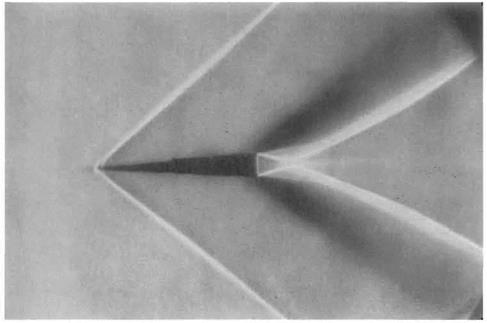
Fig. 6.40 Supersonic flow over as wedge: The schlieren method was used to obtain this flow visualization. A parallel light beam is refracted by the density differences in the flow field. It is then focused on to a knife edge and gives a flow visualization in the image on the photographic film, which takes the form of bright or dark patterns, depending on the direction the beam is bent by refraction. The main features of the flow field are the oblique bow shock wave which is slightly rounded at the nose (see Fig. 7.54, page 479), the expansion fans at the trailing edge, followed by recompression shock waves which form downstream in the wake. These last are slightly curved owing to the interaction with the expansion waves from trailing edge. (The photograph was taken by D. J. Buckingham at the School of Engineering, University of Exeter, UK.)


. Supersonic linearized theory (Ackeret&#39;s rule)

This wave equation has a general solution

ф = Fi{x – – 1 y)+F2{x + yjM2, – 1 y)

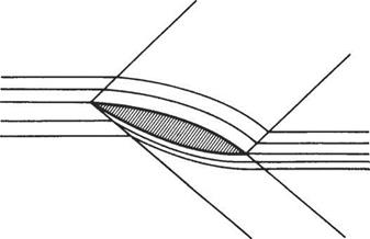
where F and F2 are two independent functions with forms that depend on the boundary conditions of the flow. In the present case physical considerations show that each function exists separately in well-defined regions of the flow (Figs 6.40, 6.41 and 6.42).

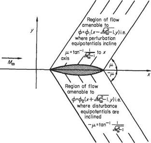
By inspection, the solution ф = F(x- y/M*, – 1 y) allows constant values of ф along the lines x – у/Ml, – 1 у = C, i. e. along the straight lines with an inclination of arc tan – 1 to the x axis (Fig. 6.42). This means that the disturbance originat­

ing on the aerofoil shape (as shown) is propagated into the flow at large, along the straight lines x = y/M – 1 у + C. Similarly, the solution ф = F2{x + T y)

. Supersonic linearized theory (Ackeret&#39;s rule)

allows constant values of ф along the straight lines x = —yjM^ — 1 y + C with inclinations of

to the axis.

It will be remembered that Mach lines are inclined at an angle

. Supersonic linearized theory (Ackeret&#39;s rule)fj, = arc tan

to the free-stream direction and thus the lines along which the disturbances are propagated coincide with Mach lines.

. Supersonic linearized theory (Ackeret&#39;s rule) Подпись: (6.142)

Since disturbances cannot be propagated forwards into supersonic flow, the appropriate solution is such that the lines incline downstream. In addition, the effect of the disturbance is felt only in the region between the first and last Mach lines and any flow conditions away from the disturbance are a replica of those adjacent to the body. Therefore within the region in which the disturbance potential exists, taking the positive solution, for example:

and

Подпись: ду д(х — y/Ml, - 1 у) ду^ дф dFy Э(х-Ум^Ту)

Подпись: (6.143)v = – yjMi – if;

. Supersonic linearized theory (Ackeret&#39;s rule)

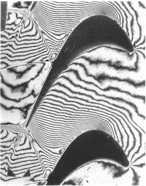
Fig. 6.41 Transonic flow through a turbine cascade: The holographic interferogram shows fringes corresponding to lines of constant density. The flow enters from the right and exits at a Mach number of about 1.3 from the left. The convex and concave surfaces of the turbine blades act as suction and pressure surfaces respectively. Various features of the flow field may be discerned from the interferogram: e. g. the gradual drop in density from inlet to outlet until the formation of a sharp density gradient marking a shock wave where the constant-density lines fold together. The shock formation at the trailing edge may be compared with Fig. 7.51 on page 476. (The phototgraph was taken by P. J. Bryanston-Cross in the Engineering Department, University of Warwick, UK.)

. Supersonic linearized theory (Ackeret&#39;s rule)

Fig. 6.42

. Supersonic linearized theory (Ackeret&#39;s rule) Подпись: (6.144)

Now the physical boundary conditions to the problem are such that the velocity on the surface of the body is tangential to the surface. This gives an alternative value for V, i. e.

where df(x)/dx is the local surface slope, f(x) the shape of the disturbing surface and Ux the undisturbed velocity. Equating Eqns (6.143) and (6.144) on the surface where у = 0:

Подпись: Ґ(х)[^l]v = 0 —

or

On integrating:

ф = № =)-^=f(x – JmI – 1 y) (6.145)

VM^-1 V

With the value of ф (the disturbance potential) found, the horizontal perturbation velocity becomes on the surface, from Eqn (6.142):

– Uoo dfx

At x from the leading edge the boundary conditions require the flow velocity to be tangential to the surface

Подпись: =k l Подпись: -U=o

Equating Eqns (6.143) and (6.144) on the surface where у = 0, Eqn (6.145) gives:

)

where є may be taken as +ve or —ve according to whether the flow is compressed or expanded respectively. Some care is necessary in designating the sign in a particular case, and in the use of this result the angle є is always measured from the undisturbed stream direction where the Mach number is M, and not from the previous flow direction if different from this.

Application to swept wings

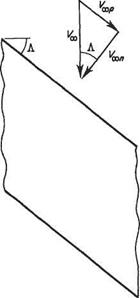
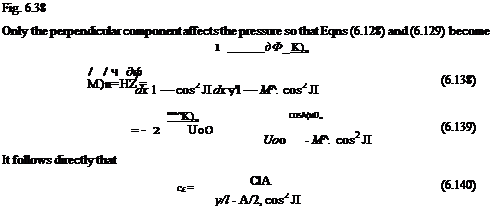
In the same way as for the incompressible case (see Section 5.7), the compressible flow over an infinite-span swept (or sheared) wing can be considered to be the superposition of two flows. One component is the flow perpendicular to the swept leading edge. The other is the flow parallel to the leading edge. The free-stream velocity now consists of two components, see Fig. 6.38. For the component perpen­dicular to the leading edge Eqn (6.118) becomes

Divide through by а2ж for the condition when V = a = a*, M^ etc.

and on substituting for p*jpoo in Eqn (6.134)

Application to swept wingsПодпись:Application to swept wings

Подпись: But Application to swept wings
Подпись: 27/(7-1)
Подпись: On rearranging

(6.137)

Application to swept wings

Application to swept wings

Application to swept wings

Example 6.8 For the NACA 4 digit series of symmetrical aerofoil sections in incompressible flow the maximum disturbance velocity (u’/Foc)maJt (corresponding to (СД^п) varies in the following way with thickness-to-chord ratio, t/c:


NACA AEROFOIL DESIGNATION

tic

(косіша*

NACA0006

0.06

0.107

NACA0008

0.08

0.133

NACA0010

0.10

0.158

NACA0012

0.12

0.188

NACA0015

0.15

0.233

NACA0018

0.18

0.278

NACA0021

0.21

0.325

NACA0024

0.24

0.374


Use this data to determine the critical Mach number for

(i) A straight wing of infinite span with a NACA 0010 wing section; and

(ii) An infinite-span wing with a 45° sweepback with the same wing section perpendicular to the leading edge.

All the 4-digit NACA wing sections are essentially the same shape, but with different thickness – to-chord ratios, as denoted by the last two digits. Thus a NACA 0010 wing section at a given freestream Mach number Mx is equivalent to a 4-digit NACA series in incompressible flow having a thickness of

(t/c)i = 0.100-MJ,

The maximum disturbance velocity, [(u//Koc)max]i for such a wing section is obtained by using linear interpolation on the data in the table given above. The maximum perturbation velocity in the actual compressible flow at Мх is given by

Подпись: (a){d/VcxOma* — j _ [(“V^xOn

Подпись: Mmax — ‘ Подпись: ■(«On Подпись: , = 2« Л +(^таЛ = м Л +МпаЛ (b) aoo  r OC J  T oc J

The maximum local Mach number is given approximately by

Equations (a) and (b) and linear interpolation of the table of data can be used to determine Мщах for a specified Moo• The results are set out in the table below

Linear interpolation between Moo = 0.75 and 0.8 gives the critical value of Mx ~ 0.78 (i. e. corresponding to Mmax = 1.0).

For the 45° swept-back wing

{t/c = 0.10^/1 – M£, cos2 Л = 0.100.0-0.5 M£,

Koo must be replaced by (Foo)„, i. e. Koo cos Л, so the maximum disturbance velocity is given by

The maximum local Mach number is then obtained from

Подпись:Application to swept wings

Thus in a similar way as for the straight wing the following table is obtained.

Constant chordwise ordinates

If the aerofoil is thin, and by definition this must be so for the small-disturbance conditions of the theory from which Eqn (6.118) is derived, the implication of this restriction is that the aerofoils are of similar shape in both planes. Take first the case of C = 1, i. e. £ = x. This gives D = В = y/l — M^ from Eqn (6.125). A solution of

Laplace plane Velocity potential

Ф=(/|~М*)ф

Подпись: Compressible xy plane Velocity potential ф Подпись: 7] = (У—м£)у

Fig. 6.35

Eqns (6.118) or (6.119) is found by applying the transformation rj = л/1 — M2 у (see Fig. 6.35). Then Eqns (6.122) and (6.123) give

дф

В

дФ

Ру.

y=о A

.9n.

V = U ^ =

c °°dx

7) = 0

= — XJ AUc°dt

but D — B, since D/C = В and C = 1.

Подпись: The transformed potential is thus
Constant chordwise ordinates Подпись: (6.126) (6.127) (6.127) (6.129)

For similar aerofoils, it is required that dy/dx = dry/d£ at corresponding points, and, for this to be so:

the relationship between lift coefficients in compressible and equivalent incompress­ible flows follows that of the pressure coefficients, i. e.

Подпись: (6.130)

Подпись: CL = -

ЖЖ

This simple use of the factor у/1 — Mj, is known as the Prandtl-Glauert rule or law and ^/1 — Mj, is known as Glauert’s factor.

Constant normal ordinates (Fig. 6.36)

Glauert,* however, developed the affine transformation implicit in taking a transformed plane distorted in the ^-direction. The consequence of this is that, for a thin aerofoil, the transformed section about which the potential Ф exists has its chordwise lengths altered by the factor 1/C.

With D = 1, i. e. Tj = y, Eqn (6.131) gives

Ч=7т=їгг (6131)

Thus the solution to Eqn (6.118) or (6.119) is found by applying the transformation and, for this and the geometrical condition of Eqns (6.122) and (6.123) to apply, A can be found. Eqn (6.122) gives

Подпись:<=u~t

By substituting Ф = Аф, Eqn (6.121), у = rf, Eqn (6.131), but from Eqn (6.122)

Подпись: A dC A dx, = UndT)= U^dy c A dC A dxV 00

To preserve the identity, A = yj — Mand the transformed potential Ф = y/X – MIq ф, as previously shown in Eqn (6.127). The horizontal flow perturb­ations, pressure coefficients and lift coefficients follow as before.

Glauert explained the latter transformation in physical terms by appealing to the fact that the flow at infinity in both the original compressible plane and the trans­formed, ideal or Laplace plane is the same, and hence the overall lifts to the systems are the same. But the chord of the ideal aerofoil is greater (due to the £ = x/y/l — distortion) than the equivalent compressible aerofoil and thus for

Constant chordwise ordinates

an identical aerofoil in the compressible plane the lift is greater than that in the ideal (or incompressible) case. The ratio Lc/Lj is as before, i. e. (1 — A/^)_1/2.

Fig. 6.36

* H. Glauert, The effect of compressibility on aerofoil lift, ARCR and M, 1135, 1927.

Critical pressure coefficient

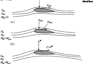
The pressure coefficient of the point of minimum pressure on an aerofoil section, using the notation of Fig. 6.37b, is

Подпись: (6.132)_ Pmin Рос

Ртпіп “I __

1,1 ,

Подпись: ~'P min Подпись: ртш .Poo Подпись: . іЩс Подпись: (6.133)

but since 2#»^oo = 2^P°°^oo’ Eqn (6.132) may be written

Подпись: ''Peril Подпись: £-1 Подпись: 7Mcrit Подпись: (6.134)

The critical condition is when first reaches the sonic pressure p* and Mx becomes Mcri, (see Fig. 6.37c). is then the critical pressure coefficient of the aerofoil section. Thus

An expression for p*lpoc in terms of Merit may be readily found by recalling the energy equation applied to isentropic flow along a streamline (see Section 6.2) which in the present notation gives

Подпись: Vl at V2 . a2OO і ЭО______ і _____

Constant chordwise ordinates

2 7-1 27-1

Constant chordwise ordinates(6.135)

In this expression Merit is the critical Mach number of the wing, and is the parameter that is often required to be found. CPcrit is the pressure coefficient at the point of maximum velocity on the wing when locally sonic conditions are just attained, and is usually also unknown in practice; it has to be predicted from the corresponding minimum pressure coefficient (CPi) in incompressible flow. CPi may be obtained from pressure-distribution data from low-speed models or, as previously, from the solu­tion of the Laplace equation of a potential flow.

The approximate relationship between ^7>crit and CPi was discussed above for two­dimensional wings. The Prandtl-Glauert rule gives:

Constant chordwise ordinates(6.136)

A simultaneous solution of Eqns (6.135) and (6.136) with a given Сл yields values of critical Mach number Merit-

The equations of motion of a compressible fluid

The equation of continuity may be recalled in Cartesian coordinates for two-dimen­sional flow in the form

Подпись:dp d(pu) d(pv) _ dt dx dy

since, in what follows, analysis of two-dimensional conditions is sufficient to demon­strate the method and derive valuable equations. The equations of motion may also be recalled in similar notation as

du du du 1 dp’

Подпись:Подпись: (6.110)dt^ Udx^~ Vdy p dx

dv dv dv 1 dp

ch Udx^ Vdy p dy.

and for steady flow

Combining Eqns (6.114b) and (6.115a) gives an expression in terms of the local velocity potential.

Even without continuing the algebra beyond this point it may be noted that the resulting nonlinear differential equation in фі is not amenable to a simple closed solution and that further restrictions on the variables are required. Since all possible restrictions on the generality of the flow properties have already been made, it is necessary to consider the nature of the component velocities themselves.

Small disturbances

So far it has been tacitly assumed that the flow is steady at infinity, and the local flow velocity has components и and v parallel to coordinate axes x and у respectively, the origin of coordinate axes furnishing the necessary datum. Let the equations now refer to a class of flows in which the velocity changes only slightly from its steady value at infinity and the velocity gradients themselves are small (thin wings at low incidence, etc). Further, identify the x axis with the undisturbed flow direction (see Fig. 6.33). The local velocity components и and v can now be written:

и — Uoo + г/. v = v’

where ti and V are small compared to the undisturbed stream velocity, and are termed the perturbation or disturbance velocities. These may be expressed non­dimensionally in the form

Similarly, дііjdx, dV/dy are small.

Making this substitution, Eqn (6.115) becomes

The equations of motion of a compressible fluid

Подпись: 2 7-І 2

(f/3C+t/)2 + /2 | a1 _ |

When the squares of small quantities are neglected this equation simplifies to

similarly

The equations of motion of a compressible fluid

я2 = aL ~ (7- )U^

Also, 1 — (У/Uoo)2— 1 from the small disturbance assumption.

Now, if the velocity potential ф is expressed as the sum of a velocity potential due to the flow at infinity plus a velocity potential due to the disturbance, i. e. Ф = Фоо + Ф, Eqn (6.114b) becomes, with slight re-arrangement:

(1-0H+S Ml

Подпись:(6.116)

where ф is the disturbance potential and 1/ = дф/дх, V = дф/ду, etc.

The right-hand side of Eqn (6.116) vanishes when М» = 0 and the coefficient of the first term becomes unity, so that the equation reduces to the Laplace equation, i. e. when Mac = 0, Eqn (6.116) becomes

Подпись:The equations of motion of a compressible fluid
&Ф і &Ф-Г) дх2 dy2

Since velocity components and their gradients are of the same small order their products can be neglected and the bracketed terms on the right-hand side of Eqn (6.116) will be negligibly small. This will control the magnitude of the right – hand side, which can therefore be assumed essentially zero unless the remaining quantity outside the bracket becomes large or indeterminate. This will occur when

M2

l-(7-l )M2ojr

L’OO

i. e. when 7 — l)i/jUoo —> 1. It can be seen that by assigning reasonable values to u’/Ux and 7 the equality will be made when Mx — 5, i. e. put rfjUoo = 0.1, 7 = 1.4, then — 25.

Within the limitations above the equation of motion reduces to the linear equation

Подпись: (6.118)<>-<>0+0-

A further limitation in application of Eqn (6.116) occurs when Мж has a value in the vicinity of unity, i. e. where the flow regime may be described as transonic. Inspection of Eqn (6.116) will also show a fundamental change in form as Mx approaches and passes unity, i. e. the quantity (1 — M^) changes sign, the equation changing from an elliptic to a hyperbolic type.

As a consequence of these restrictions the further application of the equations finds its most use in the high subsonic region where 0.4 < M00 < 0.8, and in the supersonic region where 1.2 < Mx < 5.

To extend theoretical investigation to transonic or hypersonic Mach numbers requires further development of the equations that is not considered here.

Prandtl-Glauert rule – the application of linearized theories of subsonic flow

Consider the equation (6.118) in the subsonic two-dimensional form:

(1_M-)0 + 0 = ° W6-118))

For a given Mach number M00 this equation can be written

*0+0- <««>

where В is a constant. This bears a superficial resemblance to the Laplace equation:

Подпись:д2Ф &Ф W+ dr?~0

and if the problem expressed by Eqn (6.118), that of finding ф for the subsonic compressible flow round a thin aerofoil, say, could be transformed into an equation such as (6.120), its solution would be possible by standard methods.

Figure 6.34 shows the thin aerofoil occupying, because it is thin, in the definitive sense, the Ox axis in the real or compressible plane, where the velocity potential ф exists in the region defined by the xy ordinates. The corresponding aerofoil in the Laplace or incompressible £77 plane has a velocity potential Ф. If the simple relations:

Ф = Аф, £ = Cx and 77 = Dy (6.121)

are assumed, where A, C and D are constants, the transformation can proceed.

The boundary conditions on the aerofoil surface demand that the flow be locally tangential to the surface so that in each plane respectively

Подпись: V

Compressible xy plane

‘Laplace’ £75 plane

О


x


Fig. 6.34


and


The equations of motion of a compressible fluidThe equations of motion of a compressible fluidThe equations of motion of a compressible fluid

The equations of motion of a compressible fluid

The equations of motion of a compressible fluid(6.123)

where the suffices c and і denote the compressible and incompressible planes respec­tively.

Using the simple relationships of Eqn (6.121) gives

дФ _ д{Аф) _Адф &Ф _ А &ф д£ ~д(Сх)~Сдх’ д?~С1дх2

and

дФ_Адф &Ф А &ф

dr/ D dy’ drf – D2 dy2

Thus Eqn (6.120) by substitution and rearrangement of constants becomes

The equations of motion of a compressible fluid(6.124)

Comparison of Eqns (6.124) and (6.119) shows that a solution to Eqn (6.120) (the left-hand part of Eqn (6.124)) provides a solution to Eqn (6.119) (the right-hand part of Eqn (6.119)) if the bracketed constant can be identified as the B2, i. e. when

The equations of motion of a compressible fluid(6.125)

Without generalizing further, two simple procedures emerge from Eqn (6.125). These are followed by making C or D unity when D = В от 1/C = В respectively. Since C and D control the spatial distortion in the Laplace plane the two procedures reduce to the distortion of one or the other of the two ordinates.

Subcritical flow, small perturbation theory (Prandtl-Glauert rule)

In certain cases of compressible flow, notably in supersonic flow, exact solutions to the equations of motion may be found (always assuming the fluid to be invisdd) and when these are applied to the flow in the vicinity of aerofoils they have acquired the soubriquet of exact theories. As described, aerofoils in motion near the speed of sound, in the transonic region, have a mixed-flow regime, where regions of subsonic and supersonic flow exist side by side around the aerofoil. Mathematically the analysis of this regime involves the solution of a set of nonlinear differential equations, a task that demands either advanced computational techniques or some degree of approximation.

Compressible flaw 335

The most sweeping approximations, producing the simplest solutions, are made in the present case and result in the transformation of the equations into soluble linear differential equations. This leads to the expression linearized theory associated with aerofoils in, for example, high subsonic or low supersonic flows. The approximations come about mainly from assuming that all disturbances are small disturbances or small perturbations to the free-stream flow conditions and, as a consequence, these two terms are associated with the development of the theory.

Historically, H. Glauert was associated with the early theoretical treatment of the compressibility effects on aerofoils approaching the speed of sound, and developed what are, in essence, the linearized equations for subsonic compressible flow, in R and M, 305 (1927), a note previously published by the Royal Society. In this, mention is made of the same results being quoted by Prandtl in 1922. The significant compressibility effect in subsonic flow has subsequently been given the name of the Prandtl-Glauert rule (or law).

Furthermore, although the theory takes no account of viscous drag or the onset of shock waves in localized regions of supersonic flow, the relatively crude experimental results of the time (obtained from the analysis of tests on an airscrew) did indicate the now well-investigated critical region of flight where the theory breaks down. Glauert suggested that the critical speed at which the lift falls off depends on the shape and incidence of the aerofoil, and this has since been well-substantiated.

In what follows, attention is paid to the approximate methods of satisfying the equations of motion for an invisdd compressible fluid. These depend on the simultaneous solution of the fundamental laws of conservation and of state. Initially a single equation is desired that will combine all the physical requirements. The complexity of this equation and whether it is amenable to solution will depend on the nature of the particular problem and those quantities that may be conveniently minimized.

Wings in compressible flow

In this section the compressible-flow equations in their various forms are considered in order to predict the behaviour of aerofoil sections in high sub – and supersonic flows. Except in the descriptive portions the effects of viscosity are largely neglected.

6.8.1 Transonic flow, the critical Mach number

When the air flows past a body, or vice versa, e. g. a symmetrical aerofoil section at low incidence, the local airspeed adjacent to the surface just outside the boundary layer is higher or lower than the free-stream speed depending on whether the local static pressure is less or greater than the ambient. In such a situation the value of the velocity somewhere on the aerofoil exceeds that of the free stream. Thus as the free- stream flow speed rises the Mach number at a point somewhere adjacent to the

surface reaches sonic conditions before the free stream. This point is usually the minimum-pressure point which in this case is on the upper surface. The value of the free-stream Mach number (Moo) at which the flow somewhere on the surface first reaches M = 1 is called the critical Mach number, Mc. Typically for a slender wing section at low incidence Mc may be about 0.75. Below that critical Mach number the flow is subsonic throughout.

Above the critical Mach number the flow is mixed, part supersonic part subsonic. As Moo is increased progressively from low numbers to Mc the aerodynamic char­acteristics of the aerofoil section undergo progressive and generally smooth changes, and for thin aerofoil shapes at low incidences these changes may be predicted by the small-perturbation or linearized theory outlined below due to Prandtl and Glauert.

As Moo is increased progressively beyond Mc a limited region in which the flow is supersonic develops from the point where the flow first became sonic and grows outwards and downstream, terminating in a shock wave that is at first approximately normal to the surface. As ¥„ increases the shock wave becomes stronger, longer and moves rearwards. At some stage, at a value of Mx > Mc, the velocity somewhere on the lower surface approaches and passes the sonic value, a supersonic region termin­ating in a shock wave appears on the lower surface, and that too grows stronger and moves back as the lower supersonic region increases.

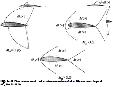
Eventually at a value of Мж close to unity the upper and lower shock waves reach the trailing edge. In their rearward movement the shock waves approach the trailing edge in general at different rates, the lower typically starting later and ahead of the upper, but moving more rapidly and overtaking the upper before they reach the trailing edge. When the free-stream Mach number has reached unity a bow shock wave appears at a small stand-off distance from the rounded leading edge. For higher Mach numbers the extremes of the bow and trailing waves incline rearwards to approach the Mach angle. For round-nosed aerofoils or bodies the bow wave is a ‘strong’ wave and always stands off, and a small subsonic region exists around the front stagnation point. The sequence is shown in Fig. 6.31. For sharp leading edges the bow shock waves are plane, and usually ‘weak’, with the downstream flow still, at a lower Mach number, supersonic. This case is dealt with separately below.

The effect on the aerofoil characteristics of the flow sequence described above is dramatic. The sudden loss of lift, increase in drag and rapid movement in centre of pressure are similar in flight to those experienced at the stall and this flight regime became known as the shock stall. Many of the effects can be minimized or delayed by design methods that are beyond the scope of the present volume.

To appreciate why the aerofoil characteristics begin to change so dramatically we must recall the properties of shock waves the first appearance of which signals the start of the change. Across the shock wave, which is the only mechanism for a finite pressure increase in supersonic flow, the pressure rise is large and sudden. Moreover the shock wave is a process accompanied by an entropy change which manifests itself as an immediate rise in drag, i. e. an irreversible conversion of mechanical energy to heat (which is dissipated) takes place and sustaining this loss results in the drag. The drag increase is directly related to the strengths of the shock waves which in turn depend on the magnitude of the supersonic regions ahead. Another contribution to the drag will occur if the boundary layer at the foot of the shock separates as a consequence of accommodating the sudden pressure rise.

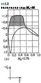
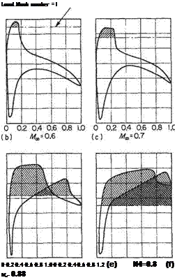
The lift on the other hand continues to rise smoothly with increase in Mx > Mc as a consequence of the increased low-pressure area on the upper surface. The sequence is seen in Fig. 6.32. The lift does not begin to decrease significantly until the low-pressure area on the lower surface becomes appreciably extensive owing to the

Wings in compressible flow

growth of the supersonic region there; Fig. 6.32c. The presence of the shock wave can be seen by the sharp vertical pressure recovery terminating the supersonic regions (shaded areas in Fig. 6.32). It is apparent that the marked effect on the lift is associated more with the growth of the shock wave on the lower surface. Movement of the centre of pressure also follows as a consequence of the varying pressure distributions and is particularly marked as the lower shock wave moves behind the upper at the higher Mach numbers approaching unity.

It may also be noted from the pressure distributions (e) and (f) that the pressure recovery at the trailing edge is incomplete. This is due to the flow separation at the feet of the shock waves. This will lead to buffeting of any control surface near the trailing edge. It is also worth noting that even if the flow remained attached the pressure information that needs to be propagated to the pressure distribution by a control movement (say) cannot be propagated upstream through the supersonic region so that the effectiveness of a trailing-edge control surface is much reduced. As the free-stream Mach number Mx becomes supersonic the flow over the aerofoil,

Wings in compressible flow Подпись: Local Mach number = I 0 0.2 0.4 0.6 0.8 1.0 0 0.2 0.4 0.6 0.8 1.2 (e) И4=0.8 (f) Ma- 0.88

Fig.6.32 Pressure distribution on two-dimensional aerofoil (Mait = 0.57) as Mx increases through Mait

except for the small region near the stagnation point, is supersonic, and the shock system stabilizes to a form similar to the supersonic case shown last in Fig. 6.31.

Two-dimensional supersonic flow past a wedge

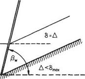
This can be described bearing the shock polar in mind. For an attached plane wave the wedge semi-vertex angle Д, say, Fig. 6.28, must be less than or equal to the maximum deflection angle (5max given by point F of the polar. The shock wave then sets itself up at the angle given by the weaker-shock case. The exit flow is uniform and parallel at a lower, in general supersonic, Mach number but with increased entropy compared with the undisturbed flow.

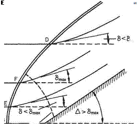
If the wedge angle Д is increased, or the free-stream conditions altered to allow Д > /3max, the shock wave stands detached from the tip of the wedge and is curved

Two-dimensional supersonic flow past a wedgeц> I

wminmmwwmwiwmwmm

Fig. 6.28

Fig. 6.29

from normal to the flow at the dividing streamline, to an angle approaching the Mach angle a long way from the axial streamline (Fig. 6.29).

All the conditions indicated by the closed loop of the shock polar can be identified:

В – on the axis the flow is undeflected but compressed through an element of normal shock to a subsonic state.

E – a little way away from the axis the stream deflection through the shock is less than the maximum possible but the exit flow is still subsonic given by the stronger shock. F – further out the flow deflection through the shock wave reaches the max­imum possible for the free-stream conditions and the exit flow is still subsonic. Beyond this point elements of shock wave behave in the weaker fashion giving a supersonic exit for streamlines meeting the shock wave beyond the intersection with the broken sonic line.

D – this point corresponds to the weaker shock wave. Further away from the axis the inclination of the wave approaches the Mach angle (the case given by point A in Fig. 6.27).

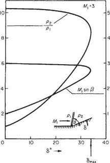
It is evident that a significant variable along the curved wave front is the product M sin /3, where /3 is the inclination of the wave locally to the incoming streamline. Uniform undisturbed flow is assumed for simplicity, but is not a necessary restric­tion. Now i < j3 < 7t/2 and M sin j3, the Mach number of the normal to the wave inlet component velocity, is thus the effective variable, that is a maximum on the axis, reducing to a minimum at the extremes of the wave (Fig. 6.30). Likewise all the other properties of the flow across the curved wave that are functions of M sin /3, will vary along the shock front. In particular, the entropy jump across the shock, which from Eqn (6.48) is

Подпись: (6.107)

Two-dimensional supersonic flow past a wedge
Подпись: /Ц>1

де 27(7 — 1) [М sin2/3 — l)3

K(7+l f 3

will vary from streamline to streamline behind the shock wave.

Two-dimensional supersonic flow past a wedge

Fig. 6.30

An entropy gradient in the flow is associated with rotational flow and thus a curved shock wave produces a flow in which vorticity exists away from the surface of the associated solid body. At low initial Mach numbers or with waves of small curvature the same approximations as those that are the consequences of assuming AS— 0 may be made. For highly curved strong shock waves, such as may occur at hypersonic speed, the downstream flow contains shock-induced vorticity, or the entropy wake as it is sometimes called, which forms a large and significant part of the flow in the immediate vicinity of the body associated with the wave.

The shock polar

Although in practice plane-shock-wave data are used in the form of tables and curves based upon the shock relationships of the previous section, the study of shock waves is considerably helped by the use of a hodograph or velocity polar diagram set up for a given free-stream Mach number. This curve is the exit velocity vector displacement curve for all possible exit flows downstream of an attached plane shock in a given undisturbed supersonic stream, and to plot it out requires rearrangement of the equations of motion in terms of the exit velocity components and the inlet flow conditions.

The shock polar

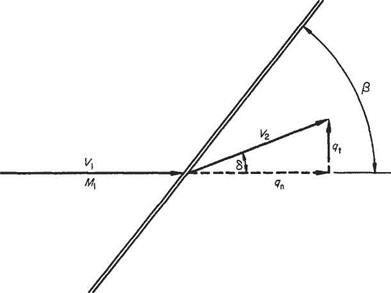
Reference to Fig. 6.25 shows the exit component velocities to be used. These are qt and qn, the radial and tangential polar components with respect to the free stream V direction taken as a datum. It is immediately apparent that the exit flow direction is given by arctan(<7t/<7n). For the wave angle /3 (recall the additional notation of

Fig. 6.25

Fig. 6.23), linear conservation of momentum along the wave front, Eqn (6.72), gives vi = V2, or, in terms of geometry:

Подпись:V cos /3 = V2 cos(/3 — 6) Expanding the right-hand side and dividing through:

V = V2 [cos S + tan /3 sin 6 or, in terms of the polar components:

y> =

The shock polar Подпись: (6.91)

which rearranged gives the wave angle

To express the conservation of momentum normal to the wave in terms of the polar velocity components, consider first the flow of unit area normal to the wave, i. e.

Подпись:Подпись: (6.93)Pi +PlM? – P2 + Pl^i

Then successively, using continuity and the geometric relations:

P2 =P + Pi V sin/3[Fi sin/3 – qn sin/3 + qn cos 0 tan <5] P2=Pi+ Pi V sin/3[(V — qn) sin/3 + cos/3]

and, using Eqn (6.89):

P2 =Pi +PV{V – qa)

Again from continuity (expressed in polar components):

pi Vi sin /3 = p2 V2 sin(/3 – S) = p2?n(sin /3 — cos /3 tan <5)

The shock polar Подпись: (6.94)

or

Подпись: (6.95)Подпись: + {Vi-qn)Again recalling Eqn (6.91) to eliminate the wave angle and rearranging: P2 Vi – qn pi

P2 Viqn – ql-qi P1V1

Finally from the energy equation expressed in polar velocity components: up to the wave

The shock polar(6.96)

and downstream from the wave

The shock polar(6.97)

Substituting for these ratios in Eqn (6.93) and isolating the exit tangential velocity component gives the following equation:

Подпись:(6.98)

that is a basic form of the shock-wave-polar equation.

To make Eqn (6.98) more amenable to graphical analysis it may be made non­dimensional. Any initial flow parameters, such as the critical speed of sound a*, the ultimate velocity c, etc., may be used but here we follow the originator A. Busemann* and divide through by the undisturbed acoustic speed a:

The shock polar(6.99)

Подпись: 7+1
Подпись: Мі-Йп-Мі)
Подпись: (6.100)

where q% = (qt/ai)2, etc. This may be further reduced to

where

The shock polar(6.101)

Inspection of Eqn (6.99) shows that the curve of the relationship between qi and qn is uniquely determined by the free-stream conditions (Mi) and conversely one shock-polar curve is obtained for each free stream Mach number. Further, since

A. Busemann, Stodola Festschrift, Ziirich, 1929.

the non-dimensional tangential component qt appears in the expression as a squared term, the curve is symmetrical about the qD axis.

Singular points will be given by setting qt = 0 and oo. For qt = 0,

(M, – qn)2(£ -Mi) = 0

giving intercepts of the qn axis at A:

qn = M (twice) (6.102)

The shock polar Подпись: (6.103)

at В

For qt oo, at C,

Подпись: (6.104)qn = -4тМ і +Mi = Mi+ —2 — 7+1 (7+l)Afi

For a shock wave to exist Mi > 1. Therefore the three points B, A and C of the qD axis referred to above indicate values of qn < Mi, = Mi, and > Mi respectively. Further, as the exit flow velocity cannot be greater than the inlet flow velocity for a shock wave the region of the curve between A and C has no physical significance and attention need be confined only to the curve between A and B.

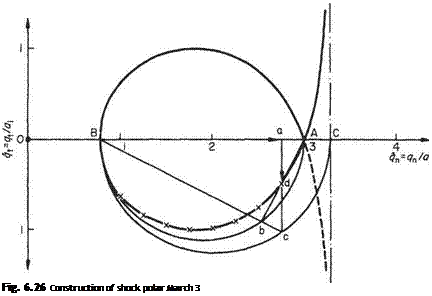
Подпись: Fig. 6.26 Construction of shock polar March 3

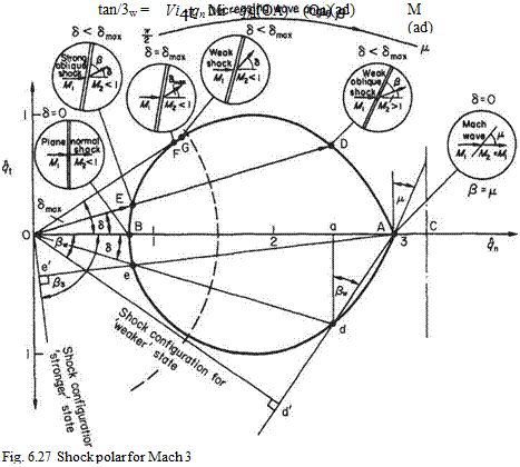
Plotting Eqn (6.98) point by point confirms the values A, В and C above. Fig. 6.26 shows the shock polar for the undisturbed flow condition of Mi — 3. The upper

branch of the curve in Fig. 6.26 is plotted point by point for the case of flow at a free stream of Mi = 3. The lower half, which is the image of the upper reflected in the qa axis shows the physically significant portion, i. e. the closed loop, obtained by a simple geometrical construction. This is as follows:

(i) Find and plot points A, В and C from the equations above. They are all explicitly functions of Mi.

(ii) Draw semi-circles (for a half diagram) with AB and CB as diameters.

(iii) At a given value qn (Oa) erect ordinates to meet the larger semi-circle in c.

(iv) Join c to В intersecting the smaller semi-circle at b.

(v) The required point d is the intercept of bA and ac.

Geometrical proof Triangles Aad and acB are similar. Therefore

ad _ aA aB ac

i. e.

The shock polar(6.105)

Again, from geometrical properties of circles,

(ac)2 = aB x aC

which substituted in Eqn (6.105) gives

Подпись: (6.106)(ad)2 = (aA)2

Introduction of the scaled values, ad = qu

aB = Oa – OB = qa – Mi, aA — OA – Oa = Mi – qn, aC = OC – Oa = [2/(7 + l)]Mi +Mj – qn

The shock polar

reveals Eqn (6.100), i. e.

Consider the physically possible flows represented by various points on the closed portion of the shock polar diagram shown in Fig. 6.27. Point A is the upper limiting value for the exit flow velocity and is the case where the free stream is subjected only to an infinitesimal disturbance that produces a Mach wave inclined at p to the free stream but no deflection of the stream and no change in exit velocity. The Mach wave angle is given by the inclination of the tangent of the curve at A to the vertical and this is the limiting case of the construction required to find the wave angle in general.

Point D is the second point at which a general vector emanating from the origin cuts the curve (the first being point E). The representation means that in going through a certain oblique shock the inlet stream of direction and magnitude given by OA is deflected through an angle 6 and has magnitude and direction given by vector OD (or Od in the lower half diagram). The ordinates of OD give the normal and tangential exit velocity components.

The shock polar

The appropriate wave angle Д* is determined by the geometrical construction shown in the lower half of the curve, i. e. by the angle Ada. To establish this recall Eqn (6.99):

Подпись: i.e. /3w = adA.
The wave angle may be seen in better juxtaposition to the deflection 6, by a small extension to the geometrical construction. Produce Ad to meet the perpendicular from О in d’. Since AaAdlHA^d’O,

Aod’ = Ada = /?w

Of the two intercepts of the curve the point D yields the weaker shock wave, i. e. the shock wave whose inclination, characteristics, etc., are closer to the Mach wave at A. The other physically possible shock to produce the deflection 6 is represented by the point E.

Point E; by a similar construction the wave angle appropriate to this shock condition is found (see Fig. 6.27), i. e. by producing Ae to meet the perpendicular
from О in e’. Inspection shows that the wave is nearly normal to the flow, the velocity drop to OE from OA is much greater than the previous velocity drop OD for the same flow deflection and the shock is said to be the stronger shock.

The shock polar

As drawn, OE is within the sonic line, which is an arc of centre О and radius [?Jat2 = 1, i-e. of radius

Point F is where the tangent to the curve through the origin meets the curve, and the angle so found by the tangent line and the qn axis is the maximum flow deflection possible in the given supersonic stream that will still retain an attached shock wave. For deflections less than this maximum the curve is intersected in two physically real points as shown above in D and E. Of these two the exit flows OE corresponding to the strong shock wave case are always subsonic. The exit flows OD due to the weaker shocks are generally supersonic but a few deflection angles close to <5max allow of weak shocks with subsonic exit flows. These are represented by point G. In practice weaker waves are experienced in uniform flows with plane shocks. When curved detached shocks exist, their properties may be evaluated locally by reference to plane-shock theory, and for the near-normal elements the strong shock representation OE may be used. Point В is the lower (velocity) limit to the polar curve and represents the normal (strongest) shock configuration in which the incident flow of velocity OA is com­pressed to the exit flow of velocity OB.

There is no flow deflection through a normal shock wave, which has the maximum reduction to subsonic velocity obtainable for the given undisturbed conditions.