Category Aerodynamics for Engineering Students

Plane oblique shock relations

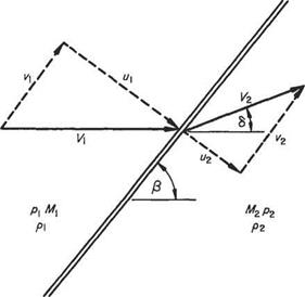
Let a datum be fixed relative to the shock wave and angular displacements measured from the free-stream direction. Then the model for general oblique flow through a plane shock wave may be taken, with the notation shown in Fig. 6.23, where V is the incident flow and V2 the exit flow from the shock wave. The shock is inclined at an angle /3 to the direction of Vi having components normal and tangential to the wave front of щ and vi respectively. The exit velocity V2 (normal м2, tangential V2 components) will also be inclined to the wave but at some angle other than /3. Relative to the incident flow direction the exit flow is deflected through 6. The equation of continuity for flow normal to the shock gives

pm = P2U2 (6.70)

Conservation of linear momentum parallel to the wave front yields

pmvi = P2U2V2 (6.71)

i. e. since no tangential force is experienced along the wave front, the product of the mass entering the wave per unit second and its tangential velocity at entry must equal

Plane oblique shock relations

Fig. 6.23

the product of the mass per second leaving the wave and the exit tangential velocity. From continuity, Eqn (6.71) yields

Подпись: Vi = v2(6.72)

Thus the velocity component along the wave front is unaltered by the wave and the model reduces to that of the one-dimensional flow problem (cf. Section 6.4.1) on which is superimposed a uniform velocity parallel to the wave front.

Now the normal component of velocity decreases abruptly in magnitude through the shock, and a consequence of the constant tangential component is that the exit flow direction, as well as magnitude, changes from that of the incident flow, and the change in the direction is towards the shock front. From this it emerges that the oblique shock is a mechanism for turning the flow inwards as well as compressing it. In the expansive mechanism for turning a supersonic flow (Section 6.6) the angle of inclination to the wave increases.

Подпись: ai a 1 MI

Since the tangential flow component is unaffected by the wave, the wave properties may be obtained from the one-dimensional flow case but need to be referred to datum conditions and direction are different from the normal velocities and direc­tions. In the present case:

or

Plane oblique shock relationsPlane oblique shock relations(6.73)

Similarly

(6.74)

The results of Section 6.4.2 may now be used directly, but with M replaced by M sin /3, and М2 by М2 sin (/3 — S). The following ratios pertain:

Plane oblique shock relations Plane oblique shock relations

Static pressure jump from Eqn (6.43):

Подпись:Подпись: (6.78)p2 _ (7+ l)Mf sin2/9

pi 2 + (7 – 1 )M sin2 /3

or from Eqn (6.46)

p_ (7 + 1 )M sin2(/? – 6)

Pi 2 + (7 — )M% sin2(/3 — 6)

Static temperature change from Eqn (6.47):

Подпись: (6.79)Tj _ 27M sin2 /3 — (7 — 1) 2 + (7 — 1 )M sin2 /3 T 7+1 (7 + )M] sin2/3

Plane oblique shock relations Подпись: (6.80)

Mach number change from Eqn (6.49):

The equations above contain one or both of the additional parameters /3 and (5 that must be known for the appropriate ratios to be evaluated.

An expression relating the incident Mach number M, the wave angle /3 and flow deflection 8 may be obtained by introducing the geometrical configuration of the flow components, i. e.

— = tan/3, — = tan(/3 — 8) Vi v2

but

Подпись: Vi = V2and ^ = K M2 Pi

Подпись: P2 Pi Подпись: tan/3 tan(/3 - (5) Подпись: (6.81)

by continuity. Thus

Equations (6.77) and (6.81) give the different expressions for pi/pi, therefore the right-hand sides may be set equal, to give:

Подпись: (6.82)tan /3 _ (7 + 1 )M sin2 /3

Plane oblique shock relations Подпись: (6.83)

tan(/3 – 8) ~ 2 + (7 – 1 )M sin2 /3

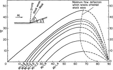
Plotting values of /3 against 8 for various Mach numbers gives the carpet of graphs shown in Fig. 6.24.

It can be seen that all the curves are confined within the M1 = 00 curve, and that for a given Mach number a certain value of deflection angle 8 up to a maximum value 8m may result in a smaller (weak) or larger (strong) wave angle /3. To solve Eqn (6.83) algebraically, i. e. to find /3 for a given M1 and 8, is very difficult. However, Collar* has shown that the equation may be expressed as the cubic

Подпись: (6.84)x3 – Cx2 — Ax + (B — AC) = 0

* A. R. Collar, JRAeS, Nov 1959.

Plane oblique shock relations

Fig. 6.24


/3°

where

x = cot Д A = M2 — 1, В = ^ ^ * М tan 5

and

C= + tan<5

Plane oblique shock relations

He further showed that the first root may be obtained from the iterative process

Plane oblique shock relationsand a suitable first approximation is x

The iteration completed yields the root xq = cot Ду where Ду is the wave angle corresponding to the weak wave, i. e. Ду is the smaller value of wave angle shown graphically above (Fig. 6.24). Extracting this root (xo) as a factor from the cubic equation (6.84) gives the quadratic equation

Подпись:x2 + (C + x0)x + [x0(C + xq) — A] — 0 having the formal solution

Now xo — cot/3w is one of the positive roots of the cubic equations and one of the physically possible solutions. The other physical solution, corresponding to the strong shock wave, is given by the positive root of the quadratic equation (6.87).

Plane oblique shock relations Plane oblique shock relations Подпись: (6.88)

It is thus possible to obtain both physically possible values of the wave angle providing the deflection angle S < <5max may be found in the normal way by differentiating Eqn (6.83) with reference to /3, with M constant and equating to zero. This gives, for the maximum value of tan 6:

Substituting back in Eqn (6.82) gives a value for tan<5n

Shock waves

The generation of the flow discontinuity called a shock wave has been discussed in Section 6.4 in the case of one-dimensional flow. Here the treatment is extended to plane oblique and curved shocks in two-dimensional flows. Once again, the thickness of the shock wave is ignored, the fluid is assumed to be inviscid and non-heat-conducting. In practice the (thickness) distance in which the gas stabilizes its properties of state from the initial to the final conditions is small but finite. Treating a curved shock as consisting of small elements of plane oblique shock

wave is reasonable only as long as its radius of curvature is large compared to the thickness.

With these provisos, the following exact, but relatively simple, extension to the one-dimensional shock theory will provide a deeper insight into those problems of shock waves associated with aerodynamics.

Mach wave interference

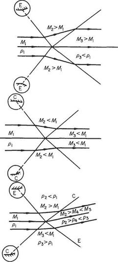
Waves of the same character and strength intersect one another with the same configuration as those of reflections from the plane surface discussed above, since the surface may be replaced by the axial streamline, Fig. 6.22a and b. When the intersecting wavelets are of opposite sign the axial streamline is bent at the point of intersection in a direction away from the expansive wavelet. This is shown in Fig. 6.22c. The streamlines are also changed in direction at the intersection of waves of the same sign but of differing turning power.

Mach wave interference

(a) Expansive wavelets


(b) Compressive wavelets


(c) Wavelets of opposite strength


Fig. 6.22 Interference of wavelets


Mach wave interference

Mach wave reflection

Mach wave reflection

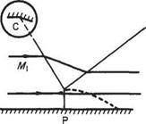
In certain situations a Mach wave, generated somewhere upstream, may impinge on a sohd surface. In such a case, unless the surface is bent at the point of contact, the wave is reflected as a wave of the same sign but at some other angle that depends on the geometry of the system. Figure 6.18 shows two wavelets, one expansive and the other compressive, each of which, being generated somewhere upstream, strikes a plane wall at P along which the supersonic stream flows, at the Mach angle

appropriate to the upstream flow. Behind the wave the flow is deflected away from the wave (and wall) in the expansive case and towards the wave (and wall) in the compressive case, with appropriate increase and decrease respectively in the Mach number of the flow.

The physical requirement of the reflected wave is contributed by the wall downstream of the point P that demands the flow leaving the reflected wave parallel to the wall. For this to be so, the reflected wave must turn the flow away from itself in the former case, expanding it further to М3 > My, and towards itself in the compressive case, thus additionally compressing and retarding its down­stream flow.

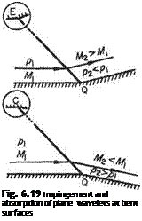
If the wall is bent in the appropriate sense at the point of impingement at an angle of sufficient magnitude for the exit flow from the impinging wave to be parallel to the wall, then the wave is absorbed and no reflection takes place, Fig. 6.19. Should the wall be bent beyond this requirement a wavelet of the opposite sign is generated.

A particular case arises in the impingement of a compressive wave on a wall if the upstream Mach number is not high enough to support a supersonic flow after the two compressions through the impinging wave and its reflection. In this case the impinging wave bends to meet the surface normally and the reflected wave forks from the incident wave above the normal part away from the wall, Fig. 6.20. The resulting wave system is Y-shaped.

On reflection from an open boundary the impinging wavelets change their sign as a consequence of the physical requirement of pressure equality with the free atmo­sphere through which the supersonic jet is flowing. A sequence of wave reflections is shown in Fig. 6.21 in which an adjacent solid wall serves to reflect the wavelets onto the jet boundary. As in a previous case, an expansive wavelet arrives from upstream and is reflected from the point of impingement Pi while the flow behind it is expanded to the ambient pressure p and deflected away from the wall. Behind the reflected wave from Pi the flow is further expanded to ps in the fashion discussed above, to bring the streamlines back parallel to the wall.

On the reflection from the free boundary in Qi the expansive wavelet P1Q1 is required to compress the flow from p-у back to p again along Q1P2. This compression

Подпись:Expansive wavelet

Compressive wavelet

Mach wave reflection

Fig. 6.20

Mach wave reflection

Fig. 6.21 Wave reflection from an open boundary

deflects the flow towards the wall where the compressive reflected wave from the wall (P2Q2) is required to bring the flow back parallel to the wall and in so doing increases its pressure to pi (greater than p). The requirement of the reflection of P2Q2 in the open boundary is thus expansive wavelet Q2P3 which brings the pressure back to the ambient value p again. And so the cycle repeats itself.

The solid wall may be replaced by the axial streamline of a (two-dimensional) supersonic jet issuing into gas at a uniformly (slightly) lower pressure. If the ambient pressure were (slightly) greater than that in the jet, the system would commence with a compressive wave and continue as above (Q1P2) onwards.

In the complete jet the diamonds are seen to be regions where the pressure is alternately higher or lower than the ambient pressure but the streamlines are axial, whereas when they are outside the diamonds, in the region of pressure equahty with the boundary, the streamlines are alternately divergent or convergent.

The simple model discussed here is considerably different from that of the flow in a real jet, mainly on account of jet entrainment of the ambient fluid which affects the reflections from the open boundary, and for a finite pressure difference between the jet and ambient conditions the expansive waves are systems of fans and the compressive waves are shock waves.

Mach waves

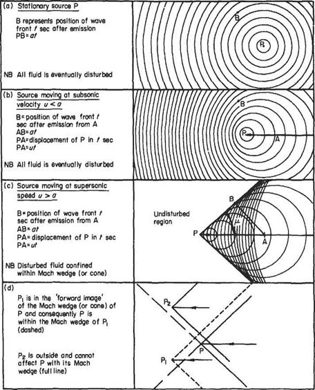
Figure 6.11 shows the wave pattern associated with a point source P of weak pressure disturbances: (a) when stationary; and (b) and (c) when moving in a straight line.

(a) In the stationary case (with the surrounding fluid at rest) the concentric circles mark the position of successive wave fronts, at a particular instant of time. In three-dimensional flow they will be concentric spheres, but a close analogy to the

Mach waves

Fig. 6.11

two-dimensional case is the appearance of the ripples on the still surface of a pond from a small disturbance. The wave fronts emanating from P advance at the acoustic speed a and consequently the radius of a wave t seconds after its emission is at. If t is large enough the wave can traverse the whole of the fluid, which is thus made aware of the disturbance.

(b) When the intermittent source moves at a speed и less than a in a straight line, the wave fronts adopt the different pattern shown in Fig. 6.11b. The individual waves remain circular with their centres on the line of motion of the source and are eccentric but non-intersecting. The point source moves through a distance ut in the time the wave moves through the greater distance at. Once again the waves signalling the pressure disturbance will move through the whole region of fluid, ahead of and behind the moving source.

(c) If the steady speed of the source is increased beyond that of the acoustic speed the individual sound waves (at any one instant) are seen in Fig. 6.11c to be eccentric intersecting circles with their centres on the line of motion. Further the circles are tangential to two symmetrically inclined lines (a cone in three dimensions) with their apex at the point source P.

While a wave has moved a distance at, the point P has moved ut and thus the semi­vertex angle

.at. 1

a = arc sin— = arc sin— (6.58)

ut M v ‘

M, the Mach number of the speed of the point P relative to the undisturbed stream, is the ratio и/a, and the angle ц is known as the Mach angle. Were the disturbance continuous, the inclined lines (or cone) would be the envelope of all the waves produced and are then known as Mach waves (or cones).

It is evident that the effect of the disturbance does not proceed beyond the Mach lines (or cone) into the surrounding fluid, which is thus unaware of the disturbance. The region of fluid outside the Mach lines (or cone) has been referred to as the zone of silence or more dramatically as the zone of forbidden signals.

It is possible to project an image wedge (or cone) forward from the apex P, Fig. 6.1 Id, and this contains the region of the flow where any disturbance Pb say, ahead would have an effect on P, since a disturbance P2 outside it would exclude P from its Mach wedge (or cone); providing always that Pi and P2 are moving at the same Mach number.

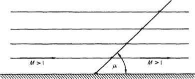
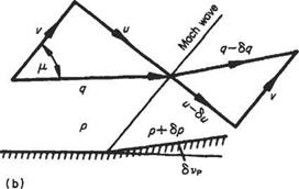
If a uniform supersonic stream M is superimposed from left to right on the flow in Fig. 6.11c the system becomes that of a uniform stream of Mach number M > 1 flowing past a weak disturbance. Since the flow is symmetrical, the axis of symmetry may represent the surface of a flat plate along which an inviscid supersonic stream flows. Any small disturbance caused by a slight irregularity, say, will be communicated to the flow at large along a Mach wave. Figure 6.12 shows the Mach wave emanating from a disturbance which has a net effect on the flow similar to a pressure pulse that leaves the downstream flow unaltered. If the pressure change across the Mach wave is to be permanent, the downstream flow direction must change. The converse is also true.

Mach waves

It is shown above that a slight pressure change in supersonic flow is propagated along an oblique wave inclined at p to the flow direction. The pressure difference is across, or normal to, the wave and the gas velocity will alter, as a consequence, in its component perpendicular to the wave front. If the downstream pressure is less, the flow velocity component normal to the wave increases across the wave so that the resultant downstream flow is inclined at a greater angle to the wave front, Fig. 6.13a. Thus the flow has been expanded, accelerated and deflected away from the wave front. On the other hand, if the downstream pressure is greater, Fig. 6.13b, the flow component across the wave is reduced, as is the net outflow velocity, which is now inclined at an angle less than p to the wave front. The flow has been compressed, retarded and deflected towards the wave.

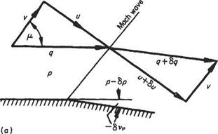
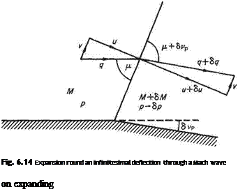
Quantitatively the turning power of a wave may be obtained as follows: Figure 6.14 shows the slight expansion round a small deflection <5vp from flow conditions p, p, M, q, etc., across a Mach wave set at p to the initial flow direction. Referring to the velocity components normal and parallel to the wave, it may be recalled that the final velocity q + 6q changes only by virtue of a change in the normal velocity component и to и + би as it crosses the wave, since the tangential velocity remains uniform throughout the field. Then, from the velocity diagram after the wave:

(q + 8q)2 = (u + Su)2 + v2

Mach waves

Mach waves

q + 2q6q + (6q)2 = u2 + 2 иёи + (6u)2 + v2 and in the limit, ignoring terms of the second order, and putting i? + v2 = q2:

qdq = udu (6.59)

Equally, from the definition of the velocity components:

и. . 1 dM v.

и = arc tan – and du =—————- , — = ~^au

v 1 + (u/v)2 v q2

but the change in deflection angle is the incremental change in Mach angle. Thus

Подпись: dvp = d /л — -^rdu ГПодпись: (6.60)v

Combining Eqns (6.59) and (6.60) yields

Подпись: 1

Подпись: Fig. 6.14 Expansion round an infinitesimal deflection through a Mach wave on expanding

dq и. и

-— = q – since – = arc tan u =

dvp v v JM2 1

T’ = ±’7^=T = ±dvptan/x ^6’61^

Ч у M2 — 1

where q is the flow velocity inclined at vp to some datum direction. It follows from Eqn (6.10), with q substituted for ji, that

Mach waves Mach waves

Fig. 6.15

or in pressure-coefficient form

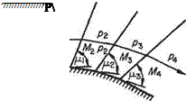
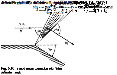
The behaviour of the flow in the vicinity of a single weak wave due to a small pressure change can be used to study the effect of a larger pressure change that may be treated as the stun of a number of small pressure changes. Consider the expansive case first. Figure 6.15 shows the expansion due to a pressure decrease equivalent to three incremental pressure reductions to a supersonic flow initially having a pressure p and Mach number M. On expansion through the wavelets the Mach number of the flow successively increases due to the acceleration induced by the successive pressure reductions and the Mach angle (p = arc sin l/M) successively decreases. Consequently, in such an expansive regime the Mach waves spread out or diverge, and the flow accelerates smoothly to the downstream conditions. It is evident that the number of steps shown in the figure may be increased or the generating wall may be continuous without the flow mechanism being altered except by the increased number of wavelets. In fact the finite pressure drop can take place abruptly, for example, at a sharp comer and the flow will continue to expand smoothly through a fan of expansion wavelets emanating from the comer. This case of two-dimensional expansive supersonic flow, i. e. round a corner, is known as the Prandtl-Meyer expansion and has the same physical mechanism as the one-dimensional isentropic supersonic accelerating flow of Section 6.2. In the Prandtl-Meyer expansion the streamlines are turned through the wavelets as the pressure falls and the flow accelerates. The flow velocity, angular deflection (from some upstream datum), pressure etc. at any point in the expansion may be obtained, with reference to Fig. 6.16.

Mach waves

Algebraic expressions for the wavelets in terms of the flow velocity be obtained by further manipulation of Eqn (6.61) which, for convenience, is recalled in the form:

Introduce the velocity component v = q cos fj, along or tangential to the wave front (Fig. 6.13). Then

Mach waves(6.64)

It is necessary to define the lower limiting or datum condition. This is most con­veniently the sonic state where the Mach number is unity, a = a*, vp = 0, and the

Mach waves Mach waves

wave angle fj, = 7t/2. In the general case, the datum (sonic) flow may be inclined by some angle a to the coordinate in use. Substitute dvp for (ljq)dqj tan/л from Eqn (6.61) and, since <7 sin/і = a, Eqn (6.64) becomes dvp — d/x = dv/a. But from the energy equation, with c = ultimate velocity, a2/(7 — 1) + (q2/2) = (c2/2) and with q2 = (v2 + a2) (Eqn (6.17)):

which allows the flow deflection in Eqn (6.67) to be expressed as a function of Mach angle, i. e.

Подпись: Vp - CL = f(/i) (6.68)

or (6.68a)

Mach waves

In his original paper Meyer[30] used the complementary angle to the Mach wave (ф) = [(тг/2) – д] and expressed the function

as the angle ф to give Eqn (6.68a) in the form

Подпись:vp — a = ф — ф

The local velocity may also be expressed in terms of the Mach angle /і by rearranging the energy equation as follows:

Подпись: 2 7- 1 2

q2 a2 c2 V + r = —

but a2 = q2 sin2 /і. Therefore or

Mach waves(6.69)

Equations (6.68) and (6.69) give expressions for the flow velocity and direction at any point in a turning supersonic flow in terms of the local Mach angle fi and hence the local Mach number M.

Values of the deflection angle from sonic conditions (vp – a), the deflection of the Mach angle from its position under sonic conditions ф, and velocity ratio q/c for a given Mach number may be computed once and for all and used in tabular form thereafter. Numerous tables of these values exist but most of them have the Mach number as dependent variable. It will be recalled that the turning power of a wave is a significant property and a more convenient tabulation has the angular deflection (vp — a) as the dependent variable, but it is usual of course to give a the value of zero for tabular purposes.1′

Mach waves

Fig. 6.17

Compression flow through three wavelets springing from the points of flow deflection are shown in Fig. 6.17. In this case the flow velocity is reducing, M is reducing, the Mach angle increases, and the compression wavelets converge towards a region away from the wall. If the curvature is continuous the large number of wavelets reinforce each other in the region of the convergence, to become a finite disturbance to form the foot of a shock wave which is propagated outwards and through which the flow properties change abruptly. If the finite compressive deflec­tion takes place abruptly at a point, the foot of the shock wave springs from the point and the initiating system of wavelets does not exist. In both cases the presence of boundary layers adjacent to real walls modifies the flow locally, having a greater effect in the compressive case.

Mach waves and shock waves in two-dimensional flow

A small deflection in supersonic flow always takes place in such a fashion that the flow properties are uniform along a front inclined to the flow direction, and their only change is in the direction normal to the front. This front is known as a wave and for small flow changes it sets itself up at the Mach angle (p) appropriate to the upstream flow conditions.

For finite positive or compressive flow deflections, that is when the downstream pressure is much greater than that upstream, the (shock) wave angle is greater than the Mach angle and characteristic changes in the flow occur (see Section 6.4). For finite negative or expansive flow deflections where the downstream pressure is less, the turning power of a single wave is insufficient and a fan of waves is set up, each inclined to the flow direction by the local Mach angle and terminating in the wave whose Mach angle is that appropriate to the downstream condition.

For small changes in supersonic flow deflection both the compression shock and expansion fan systems approach the character and geometrical properties of a Mach wave and retain only the algebraic sign of the change in pressure.

Pitot tube equation

The pressure registered by a small open-ended tube facing a supersonic stream is effectively the ‘exit’ (from the shock) total pressure />02, since the bow shock wave may be considered normal to the axial streamline, terminating in the stagnation region of the tube. That is, the axial flow into the tube is assumed to be brought to rest at pressure />02 from the subsonic flow p2 behind the wave, after it has been compressed from the supersonic region p ahead of the wave, Fig. 6.10. In some applications this pressure is referred to as the static pressure of the free or undis­turbed supersonic stream p and evaluated in terms of the free stream Mach number, hence providing a method of determining the undisturbed Mach number, as follows.

From the normal shock static-pressure ratio equation (6.43)

/>2 _ 27M – (7 ~ 1)

P 7+1

From isentropic flow relations,

/>02

P2


Pea. I


M p p щ


Pitot tube equation

Pitot tube equationPitot tube equation

Pitot tube equation

Dividing these expressions and recalling Eqn (6.49), as follows:

Подпись: № P Подпись: 7 + 1Pitot tube equation(6.57)

This equation is sometimes called Rayleigh’s supersonic Pitot tube equation.

The observed curvature of the detached shock wave on supersonic Pitot tubes was once thought to be sufficient to bring the assumption of plane-wave theory into question, but the agreement with theory reached in the experimental work was well within the accuracy expected of that type of test and was held to support the assumption of a normal shock ahead of the wave.[29]

Total pressure change across the normal shock

From the above sections it can be seen that a finite entropy increase occurs in the flow across a shock wave, implying that a degradation of energy takes place. Since, in the flow as a whole, no heat is acquired or lost the total temperature (total enthalpy) is constant and the dissipation manifests itself as a loss in total pressure. Total pressure is defined as the pressure obtained by bringing gas to rest isentropically.

Now the model flow of a uniform stream of gas of unit area flowing through a shock is extended upstream, by assuming the gas to have acquired the conditions of suffix 1 by expansion from a reservoir of pressure poi and temperature To, and downstream, by bringing the gas to rest isentropically to a total pressurepo2 (Fig. 6.8)

Total pressure change across the normal shock Подпись: (6.53)

Isentropic flow from the upstream reservoir to just ahead of the shock gives, from Eqn (6.18a):

Fig. 6.8

Подпись:(7+1)2 3.

For values of Mach number close to unity (but greater than unity) the sum of the terms involving M2 is small and very close to the value of the first term shown, so that the proportional change in total pressure through the shock wave is

Apo рої – poi _ 27 (Mj – l)3

Poi Po (7+1)2 3

Total pressure change across the normal shock
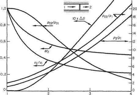
It can be deduced from the curve (Fig. 6.9) that this quantity increases only slowly from zero near Mi = 1, so that the same argument for ignoring the entropy increase (Section 6.4.6) applies here. Since from entropy considerations M> , Eqn (6.55) shows that the total pressure always drops through a shock wave. The two phenomena,

Total pressure change across the normal shock

Total pressure change across the normal shock

Mi

Fig. 6.9


i. e. total pressure drop and entropy increase, are in fact related, as may be seen in the following.

Recalling Eqn (1.32) for entropy:

eAs/c, ^Pi (Рі_Рча (Pm Pi KpiJ Poi P02

since

etc.

Pi Яві ‘

But across the shock To is constant and, therefore, from the equation of state Poi/Poi — Р02ІР02 and entropy becomes

7-1

Total pressure change across the normal shock

Now for values of Mi near unity /З 1 and

Подпись: A/>o _ 27 (M? - l)3 />oi (7 +1)2 3
Подпись: (as before, Eqn (6.55))

A/>o __ />Q1 -/>02 _ ^ _ />01 />01

Velocity change across the normal shock

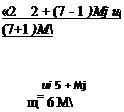
Подпись: or for air Подпись: «2 _ 2 + (7 - 1 )Mj щ (7+1 )M ui 5 + Mj щ= 6 M Velocity change across the normal shock

The velocity ratio is the inverse of the density ratio, since by continuity u2ju = рі/рг. Therefore, directly from Eqns (6.45) and (6.45a):

Velocity change across the normal shock Подпись: Cp7o - I ahead of the shock

Of added interest is the following development. From the energy equations, with cpT replaced by [7/(7 – l)]p/p, pi/pi and pijpi are isolated:

and

Подпись: downstream of the shockP2 7 V 2

Velocity change across the normal shock

The momentum equation (6.37) is rearranged with рщ = piui from the equation of continuity (6.36) to

Disregarding the uniform flow solution of щ = u2 the conservation of mass, motion and energy apply for this flow when

Подпись:2(7-1) m

uu2=——– rr-CpTo

7+1

cpTo = a*

Подпись: 2(7-1) 7+1

i. e. the product of normal velocities through a shock wave is a constant that depends on the stagnation conditions of the flow and is independent of the strength of the shock. Further it will be recalled from Eqn (6.26) that

where a* is the critical speed of sound and an alternative parameter for expressing the gas conditions. Thus, in general across the shock wave:

Подпись: щи2 a(6.52)

This equation indicates that щ > a* > u2 or vice versa and appeal has to be made to the second law of thermodynamics to see that the second alternative is inadmissible.

Mach number change across the normal shock

Mach number change across the normal shock Mach number change across the normal shock

Multiplying the above pressure (or density) ratio equations together gives the Mach number relationship directly:

2_ Ml + 5_

Подпись:

Подпись: For air Подпись: For Mi —► oo Mi —► ^ For M —► 1 Mi —> 1 Подпись: (l//7 = 0.378 for air)

Inspection of these last equations shows that Mi has upper and lower limiting values:

Thus the exit Mach number from a normal shock wave is always subsonic and for air has values between 1 and 0.378.