For the development of this theory it is assumed that the maximum aerofoil thickness is small compared to the chord length. It is also assumed that the camber-line shape only deviates slightly from the chord line. A corollary of the second assumption is that the theory should be restricted to low angles of incidence.
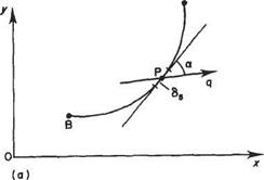
Consider a typical cambered aerofoil as shown in Fig. 4.10. The upper and lower curves of the aerofoil profile are denoted by yu and vi respectively. Let the velocities in the. v and г directions be denoted by и and v and write them in the form:
и = U cos a + и
v — U sin a + v’
|

Fig. 4.10
|
|
u’ and v’ represent the departure of the local velocity from the undisturbed free stream, and are commonly known as the disturbance or perturbation velocities. In fact, thin-aerofoil theory is an example of a small perturbation theory.
The velocity component perpendicular to the aerofoil profile is zero. This constitutes the boundary condition for the potential flow and can be expressed mathematically as:
—и sin /3 + v cos /3 = 0 at у = yu and y
Dividing both sides by cos /3, this boundary condition can be rewritten as
—(t/cosa + m’)^+ t/sina + v’ = 0 at y = yu and yi (4.11)
By making the thin-aerofoil assumptions mentioned above, Eqn (4.11) may be simplified. Mathematically, these assumptions can be written in the form
Note that the additional assumption is made that the slope of the aerofoil profile is small. These thin-aerofoil assumptions imply that the disturbance velocities are small compared to the undisturbed free-steam speed, i. e.
u’ and v4t/
Given the above assumptions Eqn (4.11) can be simplified by replacing cos a and sin a by 1 and a respectively. Furthermore, products of small quantities can be neglected, thereby allowing the term u! dy/dx to be discarded so that Eqn (4.11) becomes
 (4.12)
One further simplification can be made by recognizing that if _yu and yi c then to a sufficiently good approximation the boundary conditions Eqn (4.12) can be applied at у = 0 rather than at у = yu or y.
Since potential flow with Eqn (4.12) as a boundary condition is a linear system, the flow around a cambered aerofoil at incidence can be regarded as the superposition of two separate flows, one circulatory and the other non-circulatory. This is illustrated in Fig. 4.11. The circulatory flow is that around an infinitely thin cambered plate and the non-circulatory flow is that around a symmetric aerofoil at zero incidence. This superposition can be demonstrated formally as follows. Let
yu=yc+yt and yi=yc-yt
у = _yc(x) is the function describing the camber line and у = yt = (yu — yi)/2 is known as the thickness function. Now Eqn (4.12) can be rewritten in the form
where the plus sign applies for the upper surface and the minus sign for the lower surface.
Thus the non-circulatory flow is given by the solution of potential flow subject to the boundary condition v’ = ±Udyt/dx which is applied at у = 0 for 0 < x < c. The solution of this problem is discussed in Section 4.9. The lifting characteristics of the aerofoil are determined solely by the circulatory flow. Consequently, it is the solution of this problem that is of primary importance. Turn now to the formulation and solution of the mathematical problem for the circulatory flow.
It may be seen from Sections 4.1 and 4.2 that vortices can be used to represent lifting flow. In the present case, the lifting flow generated by an infinitely thin cambered plate at incidence is represented by a string of line vortices, each of infinitesimal strength, along the camber line as shown in Fig. 4.12. Thus the camber line is replaced by a line of variable vorticity so that the total circulation about the chord is the sum of the vortex elements. This can be written as

(4.13)
where к is the distribution of vorticity over the element of camber line 6s and circulation is taken as positive in the clockwise direction. The problem now becomes one of determining the function k{x) such that the boundary condition
is satisfied as well as the Kutta condition (see Section 4.1.1).
There should be no difficulty in accepting this idealized concept. A lifting wing may be replaced by, and produces forces and disturbances identical to, a vortex system, and Chapter 5 presents the classical theory of finite wings in which the idea of a bound vortex system is fully exploited. A wing replaced by a sheet of spanwise vortex elements (Fig. 5.21), say, will have a section that is essentially that of the replaced camber line above.
The leading edge is taken as the origin of a pair of coordinate axes x and y; Ox along the chord, and Оу normal to it. The basic assumptions of the theory permit the variation of vorticity along the camber line to be assumed the same as the variation along the Ox axis, i. e. 6s differs negligibly from 6x, so that Eqn (4.13) becomes


 Г = f kdx
Jo
Hence from Eqn (4.10) for unit span of this section the lift is given by
l = pUT = pU f kdx Jo
Alternatively Eqn (4.16) could be written with pUk = p:
1=1 pUk dx = pdx Jo Jo
Now considering unit spanwise length, p has the dimensions of force per unit area or pressure and the moment of these chordwise pressure forces about the leading edge or origin of the system is simply
Note that pitching ‘nose up’ is positive.
The thin wing section has thus been replaced for analytical purposes by a line discontinuity in the flow in the form of a vorticity distribution. This gives rise to an overall circulation, as does the aerofoil, and produces a chordwise pressure variation.
For the aerofoil in a flow of undisturbed velocity U and pressure po, the insert to Fig. 4.12 shows the static pressures pi and pj above and below the element 6s where the local velocities are U + щ and U + м2, respectively. The overall pressure difference p is p2 — p. By Bernoulli:
Pi +2^(^ + Mi)2 —Po + 2 pU2 Pi—^p(JJ + м2)2 = po —^pU2
1 m2 , /«12 ( Рг-P^jpU + -(■
and with the aerofoil thin and at small incidence the perturbation velocity ratios щ jU and uijU will be so small compared with unity that (щ/U)2 and (щ/U)2 are neglected compared with щ/U and щ! U, respectively. Then
P=P2~P =ри(щ – u2) (4.19)
The equivalent vorticity distribution indicates that the circulation due to element 6s is к 6x (6x because the camber line deviates only slightly from the Ox axis). Evaluating the circulation around 6s and taking clockwise as positive in this case, by taking the algebraic sum of the flow of fluid along the top and bottom of 6s, gives
k6x = +(U + щ)6х — (U + ui)6x = (mj — U2)6x (4-20)
Comparing (4.19) and (4.20) shows that p = pUk as introduced in Eqn (4.17).
For a trailing edge angle of zero the Kutta condition (see Section 4.1.1) requires mi = м2 at the trailing edge. It follows from Eqn (4.20) that the Kutta condition is satisfied if
к = 0 at x = c (4-21)
The induced velocity v in Eqn (4.14) can be expressed in terms of k, by considering the effect of the elementary circulation кбх at x, a distance x — x from the point considered (Fig. 4.13). Circulation кбх induces a velocity at the point x equal to
1 кбх 2ж x — x
from Eqn (4.5).
The effect of all such elements of circulation along the chord is the induced velocity v’ where
, _ J_ Ґ kdx 2nJo x-xi

|
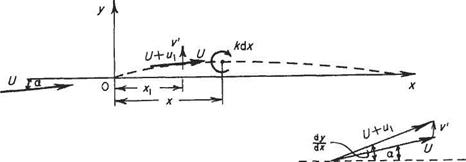
Fig. 4.13 Velocities at Xi from 0: U + iq, resultant tangential to camber lines; induced by chordwise variation in circulation; U, free stream velocity inclined at angle a to Ox
|
|

The solution for к d. v that satisfies Eqn (4.22) for a given shape of camber line (defining dVc/d. v) and incidence can be introduced in Eqns (4.17) and (4.18) to obtain the lift and moment for the aerofoil shape. The characteristics С/. and C. v/Lt follow directly and hence kep, the centre of pressure coefficient, and the angle for zero lift.
![]()


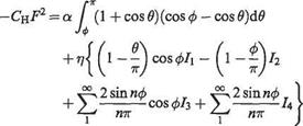


 7Г 7Г
7Г 7Г


