Category Aerodynamics for Engineering Students

The Kutta condition

How can potential flow be adapted to provide a reasonable theoretical model for the flow around an aerofoil that generates lift? The answer lies in drawing an analogy between the flow around an aerofoil and that around a spinning cylinder (see Section 3.3.10). For the latter it can be shown that when a point vortex is superimposed with a doublet on a uniform flow, a lifting flow is generated. It was explained in Section 3.3.9 that the doublet and uniform flow alone constitutes a non-circulatory irrota – tional flow with zero vorticity everywhere. In contrast, when the vortex is present the vorticity is zero everywhere except at the origin. Thus, although the flow is still irrotational everywhere save at the origin, the net effect is that the circulation is non­zero. The generation of lift is always associated with circulation. In fact, it can be shown (see Eqn 3.52) that for the spinning cylinder the lift is directly proportional to the circulation. It will be shown below that this important result can also be extended to aerofoils. The other point to note from Fig. 3.25 is that as the vortex strength, and therefore circulation, rise both the fore and aft stagnation points move downwards along the surface of the cylinder.

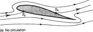
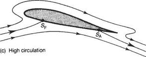
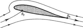
Now suppose that in some way it is possible to use vortices to generate circulation, and thereby lift, for the flow around an aerofoil. The result is shown schematically in Fig. 4.1. Figure 4.1a shows the pure non-circulatory potential flow around an aerofoil at an angle of incidence. If a small amount of circulation is added the fore and aft stagnation points, SF and SA, move as shown in Fig. 4.1b. In this case the rear stagnation point remains on the upper surface. On the other hand, if the circulation is relatively large the rear stagnation point moves to the lower surface, as shown in Fig. 4.1c. For all three of these cases the flow has to pass around the trailing edge. For an inviscid flow this implies that the flow speed becomes infinite at the trailing edge. This is evidently impossible in a real viscous fluid because viscous effects ensure that such flows cannot be sustained in nature. In fact, the only position for the rear stagnation point that is sustainable in a real flow is at the trailing edge, as illustrated in Fig. 4.Id. Only with the rear stagnation point at the trailing edge does

The Kutta condition

The Kutta condition

(b) Low circulation

The Kutta condition

The Kutta condition

(d) Circulation such that Kutta condition is satisfied

Fig. 4.1 Effect of circulation on the flow around an aerofoil at an angle of incidence

the flow leave the upper and lower surfaces smoothly at the trailing edge. This is the essence of the Kutta condition first introduced by the German mathematician Kutta.[11] Imposing the Kutta condition gives a unique way of choosing the circulation for an aerofoil, and thereby determining the lift. This is extremely important because otherwise there would be an infinite number of different lifting flows, each corres­ponding to a different value of circulation, just as in the case of the spinning cylinder

The Kutta condition

(a)


The Kutta condition

(b)

V^V^Q


‘Vi


Fig. 4.2 for which the lift generated depends on the rate of spin. In summary, the Kutta condition can be expressed as follows.

• For a given aerofoil at a given angle of attack the value of the circulation must take the unique value which ensures that the flow leaves the trailing edge smoothly.

• For practical aerofoils with trailing edges that subtend a finite angle – see Fig. 4.2a – this condition implies that the rear stagnation point is located at the trailing edge.

All real aerofoils are like Fig. 4.2a, of course, but (as in Section 4.2) for theoretical reasons it is frequently desirable to consider infinitely thin aerofoils, Fig. 4.2b. In this case and for the more general case of a cusped trailing edge the trailing edge need not be a stagnation point for the flow to leave the trailing edge smoothly.

• If the angle subtended by the trailing edge is zero then the velocities leaving the upper and lower surfaces at the trailing edge are finite and equal in magnitude and direction.

Two-dimensional wing theory

Preamble

Here the basic fluid mechanics outlined previously is applied to the analysis of the flow about a lifting wing section. It is explained that potential flow theories of themselves offer little further scope for this problem unless modified to simulate certain effects of real flows. The result is a powerful but elementary aerofoil theory capable of wide exploitation. This is derived in the general form and applied to a number of discrete aeronautical situations, including the flapped aerofoil and the jet flap. The ‘reverse’ problem is also presented: to determine the rudimentary aerofoil shape that produces certain aerodynamic performance requirements. This theory is essentially relevant to thin aerofoils but thickness parameters are added to enhance the practical applications of the method. Classical mathematical solutions are referred to, also the solutions offered towards the end of the chapter that employ computational panel methods.

4.1 Introduction

By the end of the nineteenth century the theory of ideal, or potential, flow (see Chapter 3) was extremely well-developed. The motion of an inviscid fluid was a well – defined mathematical problem. It satisfied a relatively simple linear partial differen­tial equation, the Laplace equation (see Section 3.2), with well-defined boundary conditions. Owing to this state of affairs many distinguished mathematicians were able to develop a wide variety of analytical methods for predicting such flows. Their work was and is very useful for many practical problems, for example the flow around airships, ship hydrodynamics and water waves. But for the most important practical applications in aerodynamics potential flow theory was almost a complete failure.

Potential flow theory predicted the flow field absolutely exactly for an inviscid fluid, that is for infinite Reynolds number. In two important respects, however, it did not correspond to the flow field of real fluid, no matter how large the Reynolds number. Firstly, real flows have a tendency to separate from the surface of the body. This is especially pronounced when the bodies are bluff like a circular cylinder, and in such cases the real flow bears no resemblance to the corresponding potential flow. Secondly, steady potential flow around a body can produce no force irrespective of the shape. This result is usually known as d’Alembert’s paradox after the French mathematician who first discovered it in 1744. Thus there is no prospect of using

potential flow theory in its pure form to estimate the lift or drag of wings and thereby to develop aerodynamic design methods.

Flow separation and d’Alembert’s paradox both result from the subtle effects of viscosity on flows at high Reynolds number. The necessary understanding and knowledge of viscous effects came largely from work done during the first two decades of the twentieth century. It took several more decades, however, before this knowledge was fully exploited in aerodynamic design. The great German aeronaut­ical engineer Prandtl and his research team at the University of Gottingen deserve most of the credit both for explaining these paradoxes and showing how potential flow theory can be modified to yield useful predictions of the flow around wings and thus of their aerodynamic characteristics. His boundary-layer theory explained why flow separation occurs and showed how skin-friction drag could be calculated. This theory and its later developments are described in Chapter 7 below. He also showed how a theoretical model based on vortices could be developed for the flow field of a wing having large aspect ratio. This theory is described in Chapter 5. There it is shown how a knowledge of the aerodynamic characteristics, principally the lift coefficient, of a wing of infinite span – an aerofoil – can be adapted to give estimates of the aerodynamic characteristics of a wing of finite span. This work firmly estab­lished the relevance of studying the two-dimensional flow around aerofoils that is the subject of the present chapter.

A computational routine in FORTRAN 77

In order to see how the calculation of the influence coefficients works in practice, a computational routine written in standard FORTRAN 77 is given below, with a descrip­tion of each step.

SUBROUTINE INFLU (XC, YC, AN, AT, NHAT, THAT, N, NM)

On exit XC and YC are column matrices of length N containing the co-ordinates of the col locat ion point s; AN and AT are the N*N inf luence coef f icient mat rices; and NHAT and THAT are the N*2 matrices containing the co-ordinates of the unit normal and tangent vectors, the f irst and second columns contain the x and у co-ordinates respectively. N is the number of panels and NM і s the maximum number of panels.

PARAMETER(NMAX=200,PI=3.141592654)

REAL NHAT, NTIJ, NNIJ

DIMENSION XC (NM), YC (NM), AN (NM, NM), AT (NM, NM)

DIMENSION XP (NMAX),YP (NMAX), NHAT (NM, 2 ),

& THAT(NM,2), S(NMAX)

OPEN ( 7 , FILE = ‘ POINTS. DAT ‘ , STATUS = ‘ OLD ‘)

DO 10 I = 1, N Reading in co-ordinates of panel

10 READ(7,*) XP(I), YP(I) end-points.

CLOSE(7)

DO 2 0 J = 1, N IF (J . EQ. 1) THEN XPL = XP(N)

YPL = YP(N)

ELSE

XPL = XP (J – 1)

YPL = YP (J — 1)

ENDIF

XC(J) =0.5* (XP(J)+XPL)

YC (J ) =0.5* ( YP { J ) + YPL)

S (J) =SQRT ( (XP ( J) – XPL) **2 + THAT (J, 1) = (XP (J) – XPL) /S (J) THAT(J,2) = (YP(J) – YPL)/S(J) NHAT(J,1) = – THAT(J,2)

NHAT(J,2) = THAT(J,1) CONTINUE

Calculating co-ordinates of collocation points.

(YP (J ) —YPL)**2) Calculating panel length. Calculating x co-ordinate of uni t tangent vector. Calculating у co-ordinate of unit tangent vector. Calculating x co-ordinate of unit normal vector. Calculating у co-ordinate of unit normal vector.

Calculation of the influence coefficients.

DO 3 0 I = 1, N DO 4 0 J = 1, N

IF (I. EQ. J) THEN

AN (I, J) = PI Case of і = j.

AT (I, J ) =0.0

ELSE

DX = XC (I) — XC (J) Calculat ing x and у components of line DY = YC(I) — YC(J) joining collocation point iandj

XQ = DX*THAT (J, 1) + DY*THAT (U, 2) Converting to co-ordinate system YQ = DX*NHAT (J, 1) +DY*NHAT(J,2) based on panel j.

VX = 0.5* (LOG ( (XQ + 0.5*S(J) )**2+YQ*YQ ) Using Eqn. (3.97) b —LOG ( (XQ— 0.5*S(J) ) **2 +YQ*YQ) )

VY = ATAN( (XQ+0,5*S (J) )/YQ) – Using Eqn. (3.98)

& A’TAN( (XQ-0.5*S (J) )/YQ)

Begin calculation of various scalar products of unit vectors used in Eqn. (3.99)

NTIJ = C. 0 NNI J = 0.0 TTIJ = 0.0 TNI J= 0.0 DO 50 K = l,2

NT’IJ = NHAT (I, K)*THAT (J, K) + NTIJ NNIJ = NHAT (I, К) *NHAT (J, К) + NNIJ TTI J = THAT (I, K) *THAT (J, K) + TTI J TNI J = THAT (I, K) *NHAT (J, K) + TNI J 5C CONTINUE

End calculation of scalar products.

AN(I, J) =VX*NTIJ + VY*NNIJ Using Eqn. (3.99a)

AN(I, J) =VX*TTIJ + VY*TNIJ Using Sqn. (3.99b)

ENDIF

40 CONTINUE 3 0 CONTINUE RETURN END

The routine, step by step, performs the following.

1 Discretizes the surface by assigning numbers from 1 to N to points on the surface of the aerofoil as suggested in Fig. 3.37. The x and у coordinates of these points are entered into a file named POINTS. DAT. The subroutine starts with reading these coordinates XP(f), YP(I), say x!{, y, from this file for 7 = 1 to N.

For each panel from J = 1 to N:

2 The collocation points are calculated by taking an average of the coordinates at either end of the panel in question.

3 The length S(J), i. e. Asj, of each panel is calculated.

4 The x and у components of the unit tangent vectors for each panel are calculated as follows:

J* Asj ’ jr A sj

5 The unit normal vectors are then calculated from % = —tjy and njy = tjx. The main task of the routine, that of calculating the influence coefficients, now begins.

For each possible combination of panels, i. e. 7 and J =[ to N.

6 First the special case is dealt with when і = j, i. e. the velocity induced by the sources on the panel itself at its collocation point. From Eqn (3.93, 3.97, 3.98) it is seen that

vPQx = ln(l) = 0 when xq = yQ = 0 (3.100a)

vpQy tan-1(oo) – tan-1(-oo) = 7Г when xq = yQ = 0 (3.100b)

When і Ф j the influence coefficients have to be calculated from Eqns (3.97,3.98,3.99).

7 The components DX and DY of RPq are calculated in terms of the x and у coordinates.

8 The components of Rpq in terms of the coordinate system based on panel j are then calculated as

Xq = Rpq ■ tj and Yq = Rpq ■ hj

9 VX and VY (i. e. vXg and vyQ) are evaluated using Eqns (3.97) and (3.98).

10 йі ■ tj, Пі ■ hj, ti ■ tj, and /,■ • hj are evaluated.

11 Finally the influence coefficients are evaluated from Eqn (3.99).

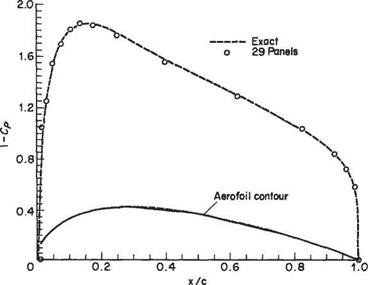
The routine presented above is primarily intended for educational purposes and has not been optimized to economize on computing time. Nevertheless, using a computer program based on the above routine and LU decomposition, accurate computations of the pressure distribution around two-dimensional aerofoils can be obtained in a few seconds with a modem personal computer. An example of such a calculation for an NACA 0024 aerofoil is presented in Fig. 3.39. In this case 29 panels were used for the complete aerofoil consisting of upper and lower surfaces.

The extension of the panel method to the case of lifting bodies, i. e. wings, is described in Sections 4.10 and 5.8. When the methods described there are used it is possible to compute the flow around the entire aircraft. Such computations are carried out routinely during aerodynamic design and have replaced wind-tunnel testing to a considerable extent. However, calculation of the potential flow around complex three­dimensional bodies is very demanding in terms of computational time and memory. In most cases around 70 to 80 per cent of the computing time is consumed in calculating the influence coefficients. Accordingly considerable effort has been devoted to devel­oping routines for carrying out these calculations efficiently.

A computational routine in FORTRAN 77

Fig. 3.39 Calculation of pressure coefficient for NACA 0024 aerofoil

What are the advantages of the panel method compared to other numerical methods such as finite differences and finite elements? Both of the latter are field methods that require that the whole of the flow field be discretized. The panel method, on the other hand, only requires the discretization of the body surface – the boundary of the flow field. The dimensions of the solution are thereby reduced by one compared to the field method. Thus for the aerofoil calcula­tion presented above the panel method required N node points along the aerofoil contour, whereas a field method would require N x N points throughout the flow field. However, this advantage is more apparent than real, since for the panel method the N x N influence coefficients need to be calculated. The real advantages of panel methods he elsewhere. First, Uke finite-element methods, but unlike finite difference methods, the panel method can readily accommodate complex geometries. In fact, an alternative and perhaps more appropriate term to panel method is boundary-element method. This name makes the connection with finite elements more clear. A second advantage compared to any field method is the ease with which panel methods can deal with an infinite flow field; note that the aerofoil in Fig. 3.39 is placed in an airflow of infinite extent, as is usual. Thirdly, as can readily be seen from the example in Fig. 3.39, accurate results can be obtained by means of a relatively coarse discretization, i. e. using a small number of panels. Lastly, and arguably the most important advantage from the viewpoint of aerodynamic design, is the ease with which modifications of the design can be incorporated with a panel method. For example, suppose the effects of under-wing stores, such as additional fuel tanks or missiles, were being investigated. If an additional store were to be added it would not be necessary to repeat the entire calculation with a panel method. It would be necessary only to calculate the additional influence coeffi­cients involving the new under-wing store. This facihty of panel methods allows the effects of modifications to be investigated rapidly during aerodynamic design.

Exercises

1 Define vorticity in a fluid and obtain an expression for vorticity at a point with polar coordinates (г, в), the motion being assumed two-dimensional. From the definition of a Une vortex as irrotational flow in concentric circles determine the variation of velocity with radius, hence obtain the stream function (ip), and the velocity potential (ф), for a line vortex. (U of L)

2 A sink of strength 120 m2s 1 is situated 2 m downstream from a source of equal

strength in an irrotational uniform stream of 30 m s’1. Find the fineness ratio of the oval formed by the streamline ip = 0. (Answer: 1.51)(CU)

3 A sink of strength 20 m2 s-1 is situated 3 m upstream of a source of 40 m2 s 1, in a uniform irrotational stream. It is found that at the point 2.5 m equidistant from both source and sink, the local velocity is normal to the line joining the source and sink. Find the velocity at this point and the velocity of the undisturbed stream.

(Answer: 1.02ms-1, 2.29ms_1)(CU)

4 A line source of strength m and a sink of strength 2m are separated a distance c.

Show that the field of flow consists in part of closed curves. Locate any stagnation points and sketch the field of flow. (U of L)

5 Derive the expression giving the stream function for irrotational flow of an

incompressible fluid past a circular cylinder of infinite span. Hence determine the position of generators on the cylinder at which the pressure is equal to that of the undisturbed stream. (Answer: ±30°, ± 150°)(U ofL)

6 Determine the stream function for a two-dimensional source of strength m. Sketch

the resultant field of flow due to three such sources, each of strength m, located at the vertices of an equilateral triangle. (U of L)

7 Derive the irrotational flow formula

P-Po = ^pU2{l — 4 sin2#)

giving the intensity of normal pressure p on the surface of a long, circular cylinder set at right-angles to a stream of velocity U. The undisturbed static pressure in the fluid is po and в is the angular distance round from the stagnation point. Describe briefly an experiment to test the accuracy of the above formula and comment on the results obtained. (U of L)

8 A long right circular cylinder of diameter am is set horizontally in a steady stream of velocity Um s-1 and caused to rotate at to rad s-1. Obtain an expression in terms of uj and U for the ratio of the pressure difference between the top and the bottom of the cylinder to the dynamic pressure of the stream. Describe briefly the behaviour of the stagnation lines of such a system as to is increased from zero, keeping V constant.

Answer. – jj~ (CU)

9 A line source is immersed in a uniform stream. Show that the resultant flow, if

irrotational, may represent the flow past a two-dimensional fairing. If a maximum thickness of the fairing is 0.15 m and the undisturbed velocity of the stream 6.0ms-1, determine the strength and location of the source. Obtain also an expression for the pressure at any point on the surface of the fairing, taking the pressure at infinity as datum. (Answer: 0.9m2 s’1, 0.0237m)(U of L)

10 A long right circular cylinder of radius am is held with its axis normal to an irrotational inviscid stream of U. Obtain an expression for the drag force acting on unit length of the cylinder due to the pressures exerted on the front half only.

^Answer: — jpU2a^j (CU)

11 Show that a velocity potential exists in a two-dimensional steady irrotational incompressible fluid motion. The stream function of a two-dimensional motion of an incompressible fluid is given by

ip^^ + bxy-^y2

where a, b and c are arbitrary constants. Show that, if the flow is irrotational, the lines of constant pressure never coincide with either the streamlines or the equipo- tential lines. Is this possible for rotational motion? (U of L)

12 State the stream function and velocity potential for each of the motions induced by a source, vortex and doublet in a two-dimensional incompressible fluid. Show that a doublet may be regarded, either as

(i) the limiting case of a source and sink, or

(ii) the limiting case of equal and opposite vortices, indicating clearly the direction of

the resultant doublet. (U of L)

13 Define (a) the stream function, (b) irrotational flow and (c) the velocity potential

for two-dimensional motion of an incompressible fluid, indicating the conditions under which they exist. Determine the stream function for a point source of strength a at the origin. Hence, or otherwise, show that for the flow due to any number of sources at points on a circle, the circle is a streamline provided that the algebraic sum of the strengths of the sources is zero. (U of L)

14 A line vortex of strength Г is mechanically fixed at the point (/, 0) referred to

a system of rectangular axes in an inviscid incompressible fluid at rest at infinity bounded by a plane wall coincident with the у-axis. Find the velocity in the fluid at the point (0, y) and determine the force that acts on the wall (per unit depth) if the pressure on the other side of the wall is the same as at infinity. Bearing in mind that this must be equal and opposite to the force acting on unit length of the vortex show that your result is consistent with the Kutta-Zhukovsky theorem. (U of L)

15 Write down the velocity potential for the two-dimensional flow about a circular

cylinder with a circulation Г in an otherwise uniform stream of velocity U. Hence show that the lift on unit span of the cylinder is pUT. Produce a brief but plausible argument that the same result should hold for the lift on a cylinder of arbitrary shape, basing your argument on consideration of the flow at large distances from the cylinder. (U of L)

16 Define the terms velocity potential, circulation, and vorticity as used in two­dimensional fluid mechanics, and show how they are related. The velocity distribu­tion in the laminar boundary layer of a wide flat plate is given by

Подпись:Подпись: 1 2 A computational routine in FORTRAN 77и = щ

where uo is the velocity at the edge of the boundary layer where у equals 8. Find the vorticity on the surface of the plate.

17

Подпись: (Answer: — (U of L) 2 8

A two-dimensional fluid motion is represented by a point vortex of strength Г set

at unit distance from an infinite straight boundary. Draw the streamlines and plot the velocity distribution on the boundary when Г = 7г. (U of L)

18 The velocity components of a two-dimensional inviscid incompressible flow are given by

. у. X

u = 2y————- т-рг. v = —2x————— 777

(x2+ff2 (x2 +y2)l/2

Подпись: ^Answer: ф = Xі +У2 + (x2 +y2)^2,C = A computational routine in FORTRAN 77 Подпись: (U of L)

Find the stream function, and the vorticity, and sketch the streamlines.

19 (a) Given that the velocity potential for a point source takes the form

Q

Подпись: a Подпись: Q 4-KZJ

where in axisymmetric cylindrical coordinates (r, z)R = s/z1 + r2, show that when a uniform stream, U, is superimposed on a point source located at the origin, there is a stagnation point located on the z-axis upstream of the origin at distance

(b) Given that in axisymmetric spherical coordinates (R, ip) the stream function for the point source takes the form

Подпись: Ф = ~Q

4-jtR

show that the streamlines passing through the stagnation point found in (a) define a body of revolution given by

2 2^(1 +cosy?)

Подпись: sin2 ifJ ~ —

Make a rough sketch of this body.

Computational (panel) methods

In Section 3.3.7, it was shown how the two-dimensional potential flow around an oval-shaped contour, the Rankine oval, could be generated by the superposition of a source and sink on the. v axis and a uniform flow. An analogous three-dimensional flow can also be generated around a Rankine body – see Section 3.4.4 above – by using a point source and sink. Thus it can be demonstrated that the potential flow around certain bodies can be modelled by placing sources and sinks in the interior of the body. However, it is only possible to deal with particular cases in this way. It is possible to model the potential flow around slender bodies or thin aerofoils of any shape by a distribution of sources lying along the x axis in the interior of the body. This slender-body theory is discussed in Section 3.4 and the analogous thin-wing theory is described in Section 4.3. However, calculations based on this theory are only approximate unless the body is infinitely thin and the slope of the body contour is very small. Even in this case the theory breaks down if the nose or leading edge is rounded because there the slope of the contour is infinite. The panel methods described here model the potential flow around a body by distributing sources over the body surface. In this way the potential flow around a body of any shape can be

see Bibliography.

P

Computational (panel) methods

Fig. 3.36


calculated to a very high degree of precision. The method was developed by Hess and Smith[9] at Douglas Aircraft Company.

If a body is placed in a uniform flow of speed U, in exactly the same way as for the Rankine oval of Section 3.3.7, or the Rankine body of Section 3.4.4, the velocity potential for the uniform flow may be superimposed on that for the disturbed flow around the body to obtain a total velocity potential of the form

Подпись: (3.87)Ф = Ux + ф

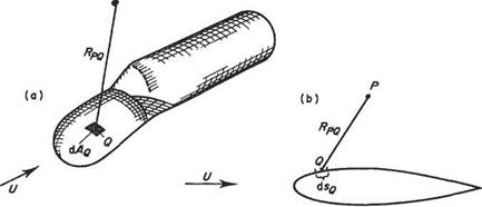
where ф denotes the so-called disturbance potential: i. e. the departure from free-stream conditions. It can be shown that the disturbance potential flow around a body of any given shape can be modelled by a distribution of sources over the body surface (Fig. 3.36). Let the source strength per unit arc of contour (or per area in the three-dimensional case) be erg. In the two-dimensional case erg dig would replace т/2тг in Eqn (3.7) and constant C can be set equal to zero without loss of generality. Thus the velocity potential at P due to sources on an element dig of arc of contour centred at point Q is given by

Подпись: (3.88a)0Pg = uglnRpgdig

where Rpq is the distance from P to Q. For the three-dimensional body <7gcL4g would replace — G/(47t) in Eqn (3.63) and the velocity potential due to the sources on an element, dv4g, of surface area at point Q is given by

Computational (panel) methods(3.88b)

The velocity potential due to all the sources on the body surface is obtained by integrating (3.88b) over the body surface. Thus following Eqn (3.87) the total velocity potential at P can be written as

Фр = Ux + §<jq In RPq6sq for the two-dimensional case, (a)

Фр = Ux + j j -~~dAQ for the three-dimensional case, (b) (3.89)

where the integrals are to be understood as being carried out over the contour (or surface) of the body. Until the advent of modern computers the result (3.89) was of relatively little practical use. Owing to the power of modem computers, however, it has become the basis of a computational technique that is now commonplace in aerodynamic design.

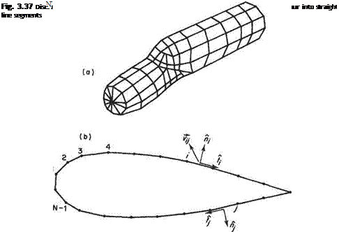
In order to use Eqn (3.89) for numerical modelling it is first necessary to ‘discretize’ the surface, i. e. break it down into a finite but quite possibly large number of separate parts. This is achieved by representing the surface of the body by a collection of quadrilateral ‘panels’ – hence the name – see Fig. 3.37a. In the case of a two­dimensional shape the surface is represented by a series of straight line segments – see Fig. 3.37b. For simplicity of presentation concentrate on the two-dimensional case. Analogous procedures can be followed for the three-dimensional body.

The use of panel methods to calculate the potential flow around a body may be best understood by way of a concrete example. To this end the two-dimensional flow around a symmetric aerofoil is selected for illustrative purposes. See Fig. 3.37b.

Computational (panel) methods

The first step is to number all the end points or nodes of the panels from 1 to N as indicated in Fig. 3.37b. The individual panels are assigned the same number as the node located to the left when facing in the outward direction from the panel. The mid-points of each panel are chosen as collocation points. It will emerge below that the boundary condition of zero flow perpendicular to the surface is applied at these points. Also define for each panel the unit normal and tangential vectors, n,- and f, respectively. Consider panels і and yin Fig. 3.37b. The sources distributed over panel j induce a velocity, which is denoted by the vector vy, at the collocation point of panel i. The components of vy perpendicular and tangential to the surface at the collocation

point і are given by the scalar (or dot) products vy • и,- and vy • (,■ respectively. Both of these quantities are proportional to the strength of the sources on panel j and therefore they can be written in the forms

Vy ■ hi = (TjNy and vy ■ /,• = ajTy (3.90)

Ny and Ту are the perpendicular and tangential velocities induced at the collocation point of panel і by sources of unit strength distributed over panel j; they are known as the normal and tangential influence coefficients.

The actual velocity perpendicular to the surface at collocation point і is the sum of the perpendicular velocities induced by each of the N panels plus the contribution due to the free stream. It is given by

N

v„i = Y/<rjNij+U-n, (3.91)

j= і

In a similar fashion the tangential velocity at collocation point і is given by

N

vSi = Y, vjTy+U-ii (3.92)

]=і

If the surface represented by the panels is to correspond to a solid surface then the actual perpendicular velocity at each collocation point must be zero. This condition may be expressed mathematically as v„, = 0 so that Eqn (3.91) becomes

N

o-yNy = – U – hfi = l, 2,…, N) (3.93)

j=і

Equation (3.93) is a system of linear algebraic equations for the Aunknown source strengths, afi = 1,2,…, N). It takes the form of a matrix equation

N<r = b (3.94)

where N is an N x N matrix composed of the elements Ny, о is a column matrix composed of the N elements cr,-, and b is a column matrix composed of the N elements — U ■ ht. Assuming for the moment that the perpendicular influence coefficients Ny have been calculated and that the elements of the right-hand column matrix b have also been calculated, then Eqn (3.94) may, in principle at least, be solved for the source strengths comprising the elements of the column matrix a. Systems of Unear equations like (3.94) can be readily solved numerically using standard methods. For the results presented here the LU decomposition was used to solve for the source strengths. This method is described by Press et al.[10] who also give Ustings for the necessary computational routines.

Once the influence coefficients Ny have been calculated the source strengths can be determined by solving the system of Eqn (3.93) by some standard numerical technique. If the tangential influence coefficients Ту have also been calculated then, once the source strengths have been determined, the tangential velocities may be obtained from Eqn (3.92). The BemoulU equation can then be used to calculate the pressure acting at collocation point z, in particular the coefficient of pressure is given by Eqn (2.24) as:

The calculation of the influence coefficient is a central and essential part of the panel method, and this is the question now addressed. As a first step consider the calculation of the velocity induced at a point P by sources of unit strength distributed over a panel centred at point Q.

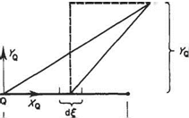
In terms of a coordinate system {xQ, yQ) measured relative to the panel (Fig. 3.38), the disturbance potential is given by integrating Eqn (3.88) over the panel. Mathematically this is expressed as follows

Computational (panel) methods(3.96)

The corresponding velocity components at P in the xq and yg directions can be readily obtained from Eqn (3.96) as

Computational (panel) methodsComputational (panel) methods(3.97)

(3.98)

Armed with these results for the velocity components induced at point P due to the sources on a panel centred at point Q return now to the problem of calculating the influence coefficients. Suppose that points P and Q are chosen to be the collocation points і and j respectively. Equations (3.97) and (3.98) give the velocity components in a coordinate system relative to panel j, whereas what are required are the velocity components perpendicular and tangential to panel i. In vector form the velocity at collocation point і is given by

Computational (panel) methods

vpq = vXQij + vyQnj

AS/2

Fig. 3.38

Therefore to obtain the components of this velocity vector perpendicular and tangential to panel і take the scalar product of the velocity vector with fi, and t, respectively to obtain

Flow around slender bodies

In the foregoing part of this section it has been shown that the flow around a class of bodies of revolution can be modelled by the use of a source and sink of equal strength. Accordingly, it would be natural to speculate whether the flow around more general body shapes could be obtained by using several sources and sinks or a distribution of them along the z axis. It is indeed possible to do this as first shown by Fuhrmann.* Two examples similar to those presented by him are shown in Fig. 3.31. Although Fuhrmann’s method could model the flow around realistic-looking bodies it suffered an important defect from the design point of view. One could calculate the body of revolution corresponding to a specified distribution of sources and sinks, but a designer would wish to be able to solve the inverse problem of how to choose the variation of source strength in order to obtain the flow around a given shape. This more practical approach became possible after Munkt introduced his slender-body theory for calculat­ing the forces on airship hulls. A brief description of this approach is given below.

Fig. 3.31 Two examples of flow around bodies of revolution generated by (a) a point source plus a linear distribution of source strength; and (b) two linear distributions of source strength. The source distributions are denoted by broken lines ♦Fuhrmann, G. (1911), Drag and pressure measurements on balloon models (in German), Z. Flugtech., 11,165. * Munk, M. M. (1924), The Aerodynamic Forces on Airship Hulls, NACA Report 184.

Подпись: Fig. 3.32 Flow over a slender body of revolution modelled by source distribution

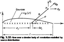
For Munk’s slender-body theory it is assumed that the radius of the body is very much smaller than its total length. The flow is modelled by a distribution of sources and sinks placed on the z axis as depicted in Fig. 3.32. In many respects this theory is analogous to the theory for calculating the two-dimensional flow around symmetric wing sections – the so-called thickness problem (see Section 4.9).

For an element of source distribution located at z = z the velocity induced at point P (r, z) is

®=^dZi <3-82)

Flow around slender bodies Flow around slender bodies Flow around slender bodies

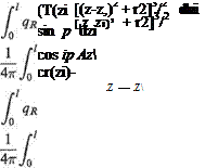
where ct-(zi) is the source strength per unit length and er(zi)dzi takes the place of Q in Eqn (3.63). Thus to obtain the velocity components in the r and z directions at P due to all the sources we resolve the velocity given by Eqn (3.82) in the two coordinate directions and integrate along the length of the body. Thus

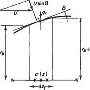
The source strength can be related to the body geometry by the following physical argument. Consider the elemental length of the body as shown in Fig. 3.33. If the body radius rj is very small compared to the length, l, then the limit r —► 0 can be considered. For this limit the flow from the sources may be considered purely radial so that the flow across the body surface of the element is entirely due to the sources within the element itself. Accordingly

2iTrqrdz = (r(zi)dzi at r = rj provided rj —► 0

But the effects of the oncoming flow must also be considered as well as the sources. The net perpendicular velocity on the body surface due to both the oncoming flow and the sources must be zero. Provided that the slope of the body contour is very

Fig. 3.33

small (i. e. dri/dz – c 1) then the perpendicular and radial velocity components may be considered the same. Thus the requirement that the net normal velocity be zero becomes (see Fig. 3.33)

qr — U sin (3 — U

dz і

Подпись: Sources

Подпись: .*DL dzi
Flow around slender bodies

Oncoming flow

So that the source strength per unit length and body shape are related as follows

(3.85)

1 *(*i)

Подпись: 4z ■■ Flow around slender bodies Подпись: (3.86)

where S is the frontal area of a cross-section and is given by S = 7rr|. In the limit as r —> 0 Eqn (3.84) simplifies to

Thus once the variation of source strength per unit length has been determined according to Eqn (3.85) the axial velocity can be obtained by evaluating Eqn (3.86) and hence the pressure evaluated from the Bernoulli equation.

It can be seen from the derivation of Eqn (3.86) that both r* and dr*/dz must be very small. Plainly the latter requirement would be violated in the vicinity of z = 0 if the body had a rounded nose. This is a major drawback of the method.

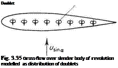
The slender-body theory was extended by Munk* to the case of a body at an angle of incidence or yaw. This case is treated as a superposition of two distinct flows as shown in Fig. 3.34. One of these is the slender body at zero angle of incidence as discussed above. The other is the slender body in a crossflow. For such a slender body the flow around a particular cross-section is closely analogous to that around a circular cylinder (see Section 3.3.9). Accordingly this flow can be modelled by a distribution of point doublets with axes aligned in the direction ♦Munk, M. M. (1934), Fluid Mechanics, Part VI, Section Q, in Aerodynamic Theory, volume 1 (ed. W. Durand), Springer, Berlin; Dover, New York.

Flow around slender bodies

„ (b)


l/sina

Подпись: Doublet Fig. 3.35 Gross-flow over slender body of revolution modelled as distribution of doublets

Fig. 3.34 Flow at angle of yaw around a body of revolution as the superposition of two flows

of the cross-flow, as depicted in Fig. 3.35. Slender-body theory will not be taken further here. The reader is referred to Thwaites and Karamcheti for further details.*

The point doublet and the potential flow around a sphere

A point doublet is produced when the source-sink pair in Fig. 3.30 become infinitely close together. This is closely analogous to line doublet described in Section 3.3.8. Mathematically the expressions for the velocity potential and stream function for a point doublet can be derived from Eqns (3.70) and (3.71) respectively by allowing a —> 0 keeping i — 2Qa fixed. The latter quantity is known as the strength of the doublet.

If a is very small a2 may be neglected compared to 2Ra cos p in Eqn (3.70) then it can be written as

Подпись: Q 47Г _______________ 1______________

(Л2 cos2 p + R2 sin2 p + 2aRcosp}1^2
1

Подпись:

Подпись: 47TR The point doublet and the potential flow around a sphere Подпись: (3.72)

{Л2 cos2 p + R2 sin2 p — 2aR cos p)

On expanding

Therefore as a —> 0 Eqn (3.72) reduces to

The point doublet and the potential flow around a sphere Подпись: (3.73)

Q

In a similar way write

Подпись: COS p’.Rcosp±a (. a

,2 =———— J———

, a a 2 = cos p ± — =F cos V R R

The point doublet and the potential flow around a sphere Подпись: (3.74)

Thus as a —* 0 Eqn (3.71) reduces to

The streamline patterns corresponding to the point doublet are similar to those depicted in Fig. 3.20. It is apparent from this streamline pattern and from the form of Eqn (3.74) that, unlike the point source, the flow field for the doublet is not
omnidirectional. On the contrary the flow field is strongly directional. Moreover, the case analysed above is something of a special case in that the source-sink pair lies on the z axis. In fact the axis of the doublet can be in any direction in three-dimensional space.

For two-dimensional flow it was shown in Section 3.3.9 that the Une doublet placed in a uniform stream produces the potential flow around a circular cylinder. Similarly it will be shown below that a point doublet placed in a uniform stream corresponds to the potential flow around a sphere.

From Eqns (3.65) and (3.73) the velocity potential for a point doublet in a uniform stream, with both the uniform stream and doublet axis aligned in the negative z direction, is given by

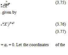
Подпись: /•i ■ , COS P 4TTR2 (3.75) ; given by 2*X’)a*v (3.76) (3.77) = qv = 0. Let the coordinates of the Подпись: ф = —U R cos p —Подпись: 4RПодпись: Яч>дф dR ]_дф R dip

Подпись: дЗ = 1 4-KU
Подпись: or sin ps = 0

stagnation points be denoted by (Rs, ps). Then from Eqn (3.77) it can be seen that either

The first of these two equations cannot be satisfied as it imphes that Rs is not a positive number. Accordingly, the second of the two equations must hold implying that

Подпись: (3.78a)Подпись: (3.78b)ps = 0 and 7Г

It now follows from Eqn (3.76) that

*-(&f

Thus there are two stagnation points on the z axis at equal distances from the origin.

The point doublet and the potential flow around a sphere Подпись: (3.79)

From Eqns (3.66) and (3.74) the stream function for a point doublet in a uniform flow is given by

Подпись: .JL 47:R Подпись: sin2 p = 0 Подпись: (3.80)

It follows from substituting Eqns (3.78b) in Eqn (3.79) that at the stagnation points ip = 0.So the streamlines passing through the stagnation points are described by

Equation (3.79) shows that when p ф 0 or тг the radius R of the stream-surface, containing the streamlines that pass through the stagnation points, remains fixed equal to Rs. R can take any value when p = 0 or 7г. Thus these streamlines define the surface of a sphere of radius Rs. This is very similar to the two-dimensional case of the flow over a circular cylinder described in Section 3.3.9.

From Eqns (3.77) and (3.78b) it follows that the velocity on the surface of the sphere is given by

q = 2U sin^

The point doublet and the potential flow around a sphere

So that using the Bernoulli equation gives that

Therefore the pressure variation over the sphere’s surface is given by

The point doublet and the potential flow around a sphere(3.81)

Again this result is quite similar to that for the circular cylinder described in Section 3.3.9 and depicted in Fig. 3.23.

Point source and sink in a uniform axisymmetric flow

Placing a point source and/or sink in a uniform horizontal stream of — U leads to very similar results as found in Section 3.3.5 for the two-dimensional case with line sources and sinks.

First the velocity potential and stream function for uniform flow, – U, in the z direction must be expressed in spherical coordinates. The velocity components qR and qv are related to — V as follows

qR = — U cos p and qv = U sin p

Using Eqn (3.60) followed by integration then gives

Подпись: дф T 6R = -Ucmv дф — — U R sin p ■ dp ф = — V R cos p+f (p) ф = —U R cos p + g(R)
f(p) and g(R) are arbitrary functions that take the place of constants of integration when partial integration is carried out. Plainly in order for the two expressions for ф derived above to be in agreement f(p) — g(R) = 0. The required expression for the velocity potential is thereby given as

Подпись:ф = —UR cos p

Similarly using Eqn (3.62) followed by integration gives

Подпись: ф = —-— cos2y> + f(R)дф j UR2

— = —U R cos p sin p =——– — sin 2p ■

dp 2

Подпись: дфПодпись: = —U R sin2 p, UR2 ., . ,

Ф =—– sin p + g{p)

Recognizing that cos 2p = 1 — 2 sin2 p it can be seen that the two expressions given above for ф will agree if the arbitrary functions of integration take the values f{R) = —U R2/4 and g(p) = 0. The required expression for the stream function is thereby given as

UR2 . 2

—-— sin p

Using Eqns (3.63) and (3.65) and Eqns (3.64) and (3.66) it can be seen that for a point source at the origin placed in a uniform flow – U along the z axis

2 * 4тг

Point source and sink in a uniform axisymmetric flow

Подпись: where Point source and sink in a uniform axisymmetric flow

(3.67a)

If this source-sink pair is placed in a uniform stream — U in the z direction it generates the flow around a body of revolution known as a Rankine body. The shape is very similar to the two-dimensional Rankine oval shown in Fig. 3.18 and described in Section 3.3.7.

Axisymmetric flow from a point source (or towards a point sink)

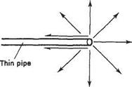
The point source and sink are similar in concept to the line source and sink discussed in Section 3.3. A close physical analogy can be found if one imagines the flow into or out of a very (strictly infinitely) thin round pipe – as depicted in Fig. 3.29. As suggested in this figure the streamlines would be purely radial in direction.

Let us suppose that the flow rate out of the point source is given by Q. Q is usually referred to as the strength of the point source. Now since the flow is purely radial away from the source the total flow rate across the surface of any sphere having its centre at the source will also be Q. (Note that this sphere is purely notional and does not represent a solid body or in any way hinder the flow.) Thus the radial velocity component at any radius R is related to Q as follows

Axisymmetric flow from a point source (or towards a point sink)

4ttR2qR – Q

It therefore follows from Eqn (3.60) that

_дф _ Q 4R dR 4ttR2

Integration then gives the expression for the velocity potential of a point source as

Подпись: (3.63), Q

4vr R

In a similar fashion an expression for stream function can be derived using Eqn (3.62) giving

Подпись: (3.64)ф = — — cos p
4-7Г

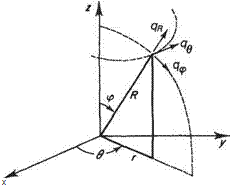
. For analysing certain two-dimensional flows, for example the flow over a circular cylinder with and without circulation, it is convenient to work with polar coord­inates. The axisymmetric equivalents of polar coordinates are spherical coordinates, for example those used for analysing the flow around spheres. Spherical coordinates are illustrated in Fig. 3.28. In this case none of the coordinate surfaces are plane and the directions of all three velocity components vary over the flow field, depending on the values of the angular coordinates в and ip. In this case the relationships between the velocity components and potential are given by

. For analysing certain two-dimensional flows, for example the flow over a circular cylinder with and without circulation, it is convenient to work with polar coord&#173;inates. The axisymmetric equivalents of polar coordinates are spherical coordinates, for example those used for analysing the flow around spheres. Spherical coordinates are illustrated in Fig. 3.28. In this case none of the coordinate surfaces are plane and the directions of all three velocity components vary over the flow field, depending on the values of the angular coordinates в and ip. In this case the relationships between the velocity components and potential are given by Подпись: (3.61)

For axisymmetric flows the variables are independent of в and in this case the continuity equation takes the form

Подпись: X

Fig. 3.28 Spherical coordinates

Подпись: _ 1 dip ^R R2 sin p dp Подпись: 1 dib R sin p dR Подпись: (3.62)

Again the relationship between the stream function and the velocity components must be such as to satisfy the continuity Eqn (3.61); hence

Axisymmetric flows (inviscid and incompressible flows)

Consider now axisymmetric potential flows, i. e. the flows around bodies such as cones aligned to the flow and spheres. In order to analyse, and for that matter to define, axisymmetric flows it is necessary to introduce cylindrical and spherical coordinate systems. Unlike the Cartesian coordinate system these coordinate systems can exploit the underlying symmetry of the flows.

3.4.1 Cylindrical coordinate system

Подпись: Яг і x

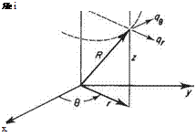
The cylindrical coordinate system is illustrated in Fig. 3.27. The three coordinate surfaces are the planes z = constant and в = constant and the surface of the cylinder having radius r. In contrast, for the Cartesian system all three coordinate surfaces are

Fig. 3.27 Cylindrical coordinates

planes. As a consequence for the Cartesian system the directions (x, y, z) of the velocity components, say, are fixed throughout the flow field. For the cylindrical coordinate system, though, only one of the directions (z) is fixed throughout the flow field; the other two (r and 6) vary throughout the flow field depending on the value of the angular coordinate в. In this respect there is a certain similarity to the polar coordinates introduced earlier in the chapter. The velocity component q, is always locally perpendicular to the cylindrical coordinate surface and qg is always tangential to that surface. Once this elementary fact is properly understood cylindrical coord­inates become as easy to use as the Cartesian system.

Подпись: дф Подпись: 1 дф Чв=~г~дв' Подпись: дф qz=Tz Подпись: (3.57)

In a similar way as the relationships between velocity potential and velocity components are derived for polar coordinates (see Section 3.1.3 above), the following relationships are obtained for cylindrical coordinates

An axisymmetric flow is defined as one for which the flow variables, i. e. velocity and pressure, do not vary with the angular coordinate в. This would be so, for example, for a body of revolution about the z axis with the oncoming flow directed along the z axis. For such an axisymmetric flow a stream function can be defined. The continuity equation for axisymmetric flow in cylindrical coordinates can be derived in a similar manner as it is for two-dimensional flow in polar coordinates (see Section 2.4.3); it takes the form

Подпись: (3.58)1 drqr dqz r dr dz

Подпись: r dz' 4z r drПодпись: (3.59)

Подпись: 1 дф Axisymmetric flows (inviscid and incompressible flows)

The relationship between stream function and velocity component must be such as to satisfy Eqn (3.58); hence it can be seen that

3.4.2 Spherical coordinates