Category Aerodynamics for Engineering Students

Bernoulli’s equation for rotational flow

Consider fluid moving in a circular path. Higher pressure must be exerted from the outside, towards the centre of rotation, in order to provide the centripetal force. That is, some outside pressure force must be available to prevent the particles moving in a straight Une. This suggests that the pressure is growing in magnitude as the radius increases, and a corollary is that the velocity of flow must fall as the distance from the centre increases.

Bernoulli's equation for rotational flow

With a segmental element at P(r, 6) where the velocity is qt only and the pressure p, the pressures on the sides will be shown as in Fig. 3.26 and the resultant pressure thrust inwards is

which reduces to

Bernoulli's equation for rotational flow(3.53)

This must provide the centripetal force = mass x centripetal acceleration

Подпись:= pr8r66q^/r

Equating (3.53) and (3.54):

Подпись: (3.55)dp _ pgj

dr r

The rate of change of total pressure H is

Bernoulli's equation for rotational flowdH = d{p + pq) = dr dr

Bernoulli's equation for rotational flow

and substituting for Eqn (3.55):

Now for this system (1 /r)(dqn/d9) is zero since the streamlines are circular and therefore the vorticity is (q{jr) + (dq{jdr) from Eqn (2.79), giving

Bernoulli's equation for rotational flow(3.56)

The flow pattern around a spinning cylinder

The flow pattern around a spinning cylinder

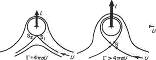
The flow pattern around the spinning cylinder is also altered as the strength of the circulation increases. In Fig. 3.25 when Г = 0 the flow pattern is that associated with the previous non-spinning case with front and rear stagnation points Si and S2

respectively, occurring on the horizontal axis. As Г is increased positively a small amount the stagnation points move down below the horizontal axis.

Since from the equation for the velocity anywhere on the surface

qi = 2U sin 6 + -— = 0 at the stagnation points
6 = arcsin(—T/AnaU)

which is negative. As Г is further increased a limiting condition occurs when 6 — —тт/2, i. e. Г = AnaU, the stagnation points merge at the bottom of the cylinder. When Г is greater than Aira U the stagnation point (S) leaves the cylinder. The cylinder continues to rotate within the closed loop of the stagnation streamline, carrying round with it a region of fluid confined within the loop.

Flow around a circular cylinder given by a doublet in a uniform horizontal flow

The stream function due to this combination is:

■0 = sin 6 — Uy 2ttr

Flow around a circular cylinder given by a doublet in a uniform horizontal flow
i. e.

This shows the streamline ф = 0 to consist of the Ox axis together with a circle, centre O, of radius ^/fi/(2ftU) = a (say).

Alternatively by converting Eqn (3.39) to polar coordinates:

Подпись: Ur sin вф = J^-sind ■

2ftr

Therefore

ф = sin 9 =0 for ф = 0

giving

sin в = 0 so в— 0 or ± 7Г

or

й~иг=0 ,=l^u=a

the two solutions as before.

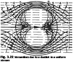
Подпись: Fig. 3.22 Streamlines due to a doublet in a uniform stream

The streamline ф = 0 thus consists of a circle and a straight line on a diameter produced (Fig. 3.22). Again in this case the streamline ф = 0 separates the flow into two distinct patterns: that outside the circle coming from the undisturbed flow a long

way upstream, to flow around the circle and again to revert to uniform flow down­stream. That inside the circle is from the doublet. This is confined within the circle and does not mingle with the horizontal stream at all. This inside flow pattern is usually neglected. This combination is consequently a mathematical device for giving expression to the ideal two-dimensional flow around a circular cylinder.

The velocity potential due to this combination is that corresponding to a uniform stream flowing parallel to the Ox axis, superimposed on that of a doublet at the origin. Putting x = r cos #:

li

ф = — Ur cos 0 —cos 9

Flow around a circular cylinder given by a doublet in a uniform horizontal flow(3.41)

Подпись: where а = у/ілІ(2тгЦ) is the radius of the streamline ф = 0.The streamlines can be obtained directly by plotting using the superposition method outlined in previous cases. Rewriting Eqn (3.39) in polar coordinates

Lb.

ф = -—sin# — Ur sin 9 27ГГ

Flow around a circular cylinder given by a doublet in a uniform horizontal flow

and rearranging, this becomes

and with fiKlirU) = a2 a constant (a = radius of the circle^ = 0)

ф = UsmO^-rj (3.42)

Differentiating this partially with respect to r and # in turn will give expressions for the velocity everywhere, i. e.:

Flow around a circular cylinder given by a doublet in a uniform horizontal flow(3.43)

Putting r = a (the cylinder radius) in Eqns (3.43) gives:

(i) qn = Ucos#[l – 1] = 0 which is expected since the velocity must be parallel to the surface everywhere, and

(ii) qt= U sin # [1 + 1] = 2U sin #.

Therefore the velocity on the surface is 2Usin# and it is important to note that the velocity at the surface is independent of the radius of the cylinder.

The pressure distribution around a cylinder

If a long circular cylinder is set in a uniform flow the motion around it will, ideally, be given by the expression (3.42) above, and the velocity anywhere on the surface by the formula

Flow around a circular cylinder given by a doublet in a uniform horizontal flow

By the use of Bernoulli’s equation, the pressure p acting on the surface of the cylinder where the velocity is q can be found. If po is the static pressure of the free stream where the velocity is U then by Bernoulli’s equation:

Therefore

Flow around a circular cylinder given by a doublet in a uniform horizontal flow(3.45)

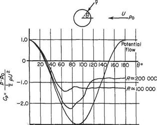
Plotting this expression gives a curve as shown on Fig. 3.23. Important points to

note are:

(1) At the stagnation points (0° and 180°) the pressure difference (p – po) is positive and equal to pU2.

(2) At 30° and 150° where sin# = A, (p — po) is zero, and at these points the local velocity is the same as that of the free stream.

(3) Between 30° and 150°CP is negative, showing that p is less than po.

(4) The pressure distribution is symmetrical about the vertical axis and therefore there is no drag force. Comparison of this ideal pressure distribution with that obtained by experiment shows that the actual pressure distribution is similar to the theoretical value up to about 70° but departs radically from it thereafter. Furthermore, it can be seen that the pressure coefficient over the rear portion of the cylinder remains negative. This destroys the symmetry about the vertical axis and produces a force in the direction of the flow (see Section 1.5.5).

Flow around a circular cylinder given by a doublet in a uniform horizontal flow

Flow around a circular cylinder given by a doublet in a uniform horizontal flow

-3.0


Flow around a circular cylinder given by a doublet in a uniform horizontal flow

(3.46)


ф = Ur Sin в ( – г – — 1 — — ІП – 1 1 2-k a


and differentiating partially with respect to r and в the velocity components of the flow anywhere on or outside the cylinder become, respectively:


q,-~Tr-UsM^~+’)+2„

?- = 7 % = Ucose(^-1


(3.47)


and


q = Jql + 4t

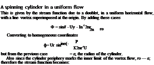
On the surface of the spinning cylinder r = a. Therefore,

Qn = 0


(3.48)


ot = 2 U sin# + -— 2тта


Therefore


217 sin#+ -— 2-ка


qt


and applying Bernoulli’s equation between a point a long way upstream and a point on the cylinder where the static pressure is p

1 , 1 ,

Po+^PU =P + 2™


-г+і„(2Р«пв+і)


Therefore


1-|2siDS + 2^)


(3.49)


Po=^pU2


This equation differs from that of the non-spinning cylinder in a uniform stream of the previous section by the addition of the term (Tj(2-KUa)) = В (a constant), in the squared bracket. This has the effect of altering the symmetry of the pressure dis­tribution about a horizontal axis. This is indicated by considering the extreme top and bottom of the cylinder and denoting the pressures there by pj and рв respect­ively. At the top p =pr when 9 = тг/2 and sin в = 1. Then Eqn (3.49) becomes

PT-po=pU2{-[2 + B2)

Подпись:Подпись: (3.51)= – X-pU2(3 + 4B + Bz)

At the bottom p — Pb when 9 = – тг/2 and sin 9 = -1:

Pb-Po = -pU2{3-4B + B2)

Flow around a circular cylinder given by a doublet in a uniform horizontal flow

Clearly (3.50) does not equal (3.51) which shows that a pressure difference exists between the top and bottom of the cylinder equal in magnitude to

which suggests that if the pressure distribution is integrated round the cylinder then a resultant force would be found normal to the direction of motion.

The normal force on a spinning circular cylinder in a uniform stream

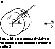
Consider a surface element of cylinder of unit span and radius a (Fig. 3.24). The area of the element = а 89 x 1, the static pressure acting on element = p, resultant force = ip— po)a69, vertical component = ip— po)a69 sin9.

Flow around a circular cylinder given by a doublet in a uniform horizontal flow

Substituting for ip — po) from Eqn (3.49) and retaining the notation В = rj2irUa, the vertical component of force acting on the element = pU2[ 1 — (2 sin 9 + Bf]a 69 sin 9. The total vertical force per unit span by integration is (/ positive upwards):

which becomes

Flow around a circular cylinder given by a doublet in a uniform horizontal flow

Подпись: P Fig. 3.24 The pressure and velocity on the surface of unit length of a cylinder of radius a

[sin 9( 1 – B2) – 4В sin2 9 — 4 sin3 9]й9

On integrating from 0 to 2тг the first and third terms vanish leaving

Flow around a circular cylinder given by a doublet in a uniform horizontal flow

Flow around a circular cylinder given by a doublet in a uniform horizontal flow

r2 r

Replacing В by Гj2irUa and cancelling gives the equation for the lift force per unit span

l Подпись: (3.52)= pUT

The lift per unit span in N is equal to the product of density p, the linear velocity U, and the circulation Г.

This expression is the algebraic form of the Kutta-Zhukovsky theorem, and is valid for any system that produces a circulation superimposed on a linear velocity (see Section 4.1.3). The spinning cylinder is used here as it lends itself to stream function theory as well as being of interest later.

It is important to note that the diameter of the cylinder has no influence on the final expression, so if a line vortex of strength Г moved with velocity U in a uniform flow of density p, the same sideways force / = pUT per unit length of vortex would be found. This sideways force commonly associated with a spinning object moving through the air has been recognized and used in ball games since ancient times. It is usually referred to as the Magnus effect after the scholar and philosopher Magnus.

Doublet

A doublet is a source and sink combination, as described above, but with the separation infinitely small. A doublet is considered to be at a point, and the definition of the strength of a doublet contains the measure of separation. The strength (ц) of a doublet is the product of the infinitely small distance of separation, and the strength of source and sink. The doublet axis is the line from the sink to the source in that sense.

Fig. 3.19

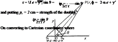
The streamlines due to a source and sink combination are circles each intersecting in the source and sink. As the source and sink approach, the points of intersection also approach until in the limit, when separated by an infinitesimal distance, the circles are all touching (intersecting) at one point – the doublet. This can be shown as follows. For the source and sink:

ip = (m/2n)l3 from Eqn (3.26)

By constructing the perpendicular of length p from the source to the line joining the sink and P it can be seen that as the source and sink approach (Fig. 3.19),

p —> 2c sin 9 and also p —> r(3

Therefore in the limit

V7*2+.

Подпись:

Doublet Подпись: (3.36) (3.37)

2c sin 9 = rp or /?

and rearranging gives

P+rtwy = 0

which, when ф is a constant, is the equation of a circle.

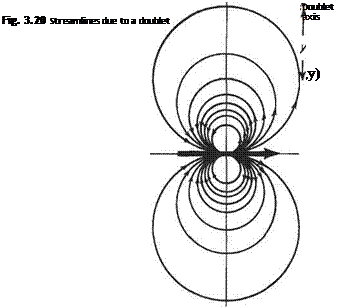
Therefore, lines of constant ip are circles of radius p/(4mp) and centres (0, p/(4irib)) (Fig. 3.20), i. e. circles, with centres lying on the Оу axis, passing through the origin as deduced above.

Doublet

Fig. 3.21

Consider again a source and sink set a very small distance, 2c, apart (Fig. 3.21). Then[8]

A source set upstream of an equal sink in a uniform stream

A source set upstream of an equal sink in a uniform stream Подпись: (3.31)

The stream function due to this combination is:

Here the first term represents a source and sink combination set with the source to the right of the sink. For the source to be upstream of the sink the uniform stream must be from right to left, i. e. negative. If the source is placed downstream of the sink an entirely different stream pattern is obtained.

The velocity potential at any point in the flow due to this combination is given by:

Подпись: (3.32)ф = In — – Ur sin в 2тГ Г2

A source set upstream of an equal sink in a uniform stream Подпись: (3.33)

or

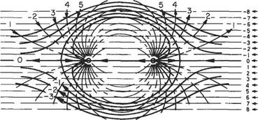
The streamline ф = 0 gives a closed oval curve (not an ellipse), that is symmetrical about the Ox and Оу axes. Flow of stream function ф greater than ф — 0 shows the flow round such an oval set at zero incidence in a uniform stream. Streamlines can be obtained by plotting or by superposition of the separate standard flows (Fig. 3.18). The streamline ф = 0 again separates the flow into two distinct regions. The first is wholly contained within the closed oval and consists of the flow out of the source and into the sink. The second is that of the approaching uniform stream which flows around the oval curve and returns to its uniformity again. Again replacing ф = 0 by a solid boundary, or indeed a solid body whose shape is given by ф = 0, does not influence the flow pattern in any way.

A source set upstream of an equal sink in a uniform stream

Thus the stream function ф of Eqn (3.31) can be used to represent the flow around a long cylinder of oval section set with its major axis parallel to a steady stream. To find the stream function representing a flow round such an oval cylinder it must be possible to obtain m and c (the strengths of the source and sink and distance apart) in terms of the size of the body and the speed of the incident stream.

Suppose there is an oval of breadth 2bo and thickness 2to set in a uniform flow of U. The problem is to find m and c in the stream function, Eqn (3.31), which will then represent the flow round the oval.

A source set upstream of an equal sink in a uniform stream Подпись: Uy

(a) The oval must conform to Eqn (3.31):

(b)

A source set upstream of an equal sink in a uniform stream Подпись: Uto

On streamline ф = 0 maximum thickness to occurs at x — 0, у = t0. Therefore, substituting in the above equation:

A source set upstream of an equal sink in a uniform stream Подпись: (3.34)

and rearranging

(c) A stagnation point (point where the local velocity is zero) is situated at the ‘nose’ of the oval, i. e. at the point у = 0, x = bo, i. e.:

_ дф d (m _y 2су

дф m 1 (x2 + y2 — c2)2c — 2y 2cy

and putting у = 0 and x — bo with дф/ду = 0:

m {bl – c2)2c _ m 2c _

2тг(г>2_с2)2 2тг bl~c2

Therefore

Л2 – r2

m = irU-Z————————————– (3.35)

c

The simultaneous solution of Eqns (3.34) and (3.35) will furnish values of m and c to satisfy any given set of conditions. Alternatively (a), (b) and (c) above can be used to find the thickness and length of the oval formed by the streamline ф = 0. This form of the problem is more often set in examinations than the preceding one.

Source-sink pair

Source-sink pair

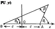
This is a combination of a source and sink of equal (but opposite) strengths situated a distance 2c apart. Let ±m be the strengths of a source and sink situated at points A (c, 0) and В (—c, 0), that is at a distance of c m on either side of the origin (Fig. 3.15). The stream function at a point P(jc, у), (г, 0) due to the combination is

Source-sink pair(3.26)

Подпись: tan 0i = ^ , tan 02 = ^ X — C X + c

Transposing the equation to Cartesian coordinates:

Therefore

Source-sink pair(3.27)

and substituting in Eqn (3.26):

Source-sink pair

Подпись: PU ,y)

(3.28)

Подпись: or Source-sink pair
Source-sink pair

To find the shape of the streamlines associated with this combination it is neces­sary to investigate Eqn (3.28). Rearranging:

or

x2 +У2 — 2ccot^^y — c2 = 0 m

which is the equation of a circle of radius csjcot2 (2тгф/т) + 1, and centre ccot(2Tnp/m).

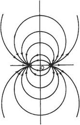
Therefore streamlines for this combination consist of a series of circles with centres on the Оу axis and intersecting in the source and sink, the flow being from the source to the sink (Fig. 3.16).

Consider the velocity potential at any point P(r, 9){x, y).*

Подпись:m r m r2 m, r i

: — In — – — In — = — In —

27Г r0 2tt ro 2іг Г2

Source-sink pair

rf = (x — c)2+y2 = x2+y2 + c2 — 2 xc = (x + c)2 + y2 = x2 + y2 + c2 + 2 xc

Fig. 3.16 Streamlines due to a source and sink pair

* Note that here r0 is the radius of the equipotential ф = 0 for the isolated source and the isolated sink, but not for the combination.

Source-sink pair

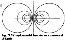
Therefore, the equipotentials due to a source and sink ombination are sets of eccentric non-intersecting circles with their centres on the Ox axis (Fig. 3.17). This pattern is exactly the same as the streamline pattern due to point vortices of opposite sign separated by a distance 2c.

A source in a uniform horizontal stream

Let a source of strength m be situated at the origin with a uniform stream of — U moving from right to left (Fig. 3.13).

Then

A source in a uniform horizontal stream(3.18)

which is a combination of two previous equations. Eqn (3.18) can be rewritten

Подпись:ф = tan 1 – — Uy
2тг x

A source in a uniform horizontal stream

to make the variables the same in each term. Combining the velocity potentials:

or

A source in a uniform horizontal stream(3.20)

or in polar coordinates

Подпись: (3.21)m r

ф = —In—- UrcosO

2тг r0

These equations give, for constant values of ф, the equipotential lines everywhere normal to the streamlines.

A source in a uniform horizontal stream

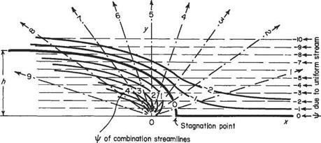
Streamline patterns can be found by substituting constant values for ф and plot­ting Eqn (3.18) or (3.19) or alternatively by adding algebraically the stream functions due to the two cases involved. The second method is easier here.

Method (see Fig. 3.14)

(1) Plot the streamlines due to a source at the origin taking the strength of the source equal to 20m2s_I (say). The streamlines are тг/10 apart. It is necessary to take positive values of у only since the pattern is symmetrical about the Ox axis.

(2) Superimpose on the plot horizontal lines to a scale so that ip = — (Jy = — I, —2, —3, etc., are lines about 1 unit apart on the paper. Where the lines intersect, add the values of ip at the Unes of intersection. Connect up all points of constant – ip (streamlines) by smooth lines.

The resulting flow pattern shows that the streamlines can be separated into two distinct groups: (a) the fluid from the source moves from the source to infinity without mingling with the uniform stream, being constrained within the streamline ip = 0; (b) the uniform stream is split along the Ox axis, the two resulting streams being deflected in their path towards infinity by – ip = 0.

It is possible to replace any streamline by a solid boundary without interfering with the flow in any way. If – ip = 0 is replaced by a solid boundary the effects of the source are truly cut off from the horizontal flow and it can be seen that here is a mathem­atical expression that represents the flow round a curved fairing (say) in a uniform flow. The same expression can be used for an approximation to the behaviour of a wind sweeping in off a plain or the sea and up over a cliff. The upward components of velocity of such an airflow are used in soaring.

The vertical velocity component at any point in the flow is given by —dip/dx. Now

V^tan-‘Q-t/y (Eqn(3.19))

Подпись: m Подпись: 1 Подпись: -У

дф _ m 9tan-I(y/x) d(y/x) дх 2-її d(y/x) dx

2tt 1 + (y/xf x2

A source in a uniform horizontal stream

due to source at origin

A source in a uniform horizontal stream


_дФ_п_т * T,

U ду ° 2tt x2+y2 U

= ^ = n= m У

dx 2-k x2 + y2

or


m


2-kx2 + y2


and this is upwards.

This expression also shows, by comparing it, in the rearranged form x2+y2- (mj2irv)y = 0, with the general equation of a circle (x2 + y2 + 2gx + 2hy +f = 0), that lines of constant vertical velocity are circles with centres (0, mjAnv) and radii mjAirv.

The ultimate thickness, 2h (or height of cliff h) of the shape given by ф = 0 for this combination is found by putting у = h and 9 = tv in the general expression, i. e. substituting the appropriate data in Eqn (3.18):


ф = г^–Ш = 0

27Г


Therefore


h = m/2U


(3.22)


Note that when в = 7г/2, у — h/2.


The position of the stagnation point

By finding the stagnation point, the distance of the foot of the cliff, or the front of the fairing, from the source can be found. A stagnation point is given by и = 0, v = 0, i. e.


(3.23)

(3.24)


From Eqn (3.24) v = 0 when у = 0, and substituting in Eqn (3.23) when у = 0 and

x — xo:

„ /и 1 „

u = 0 = ——– U

2ttxq


when


xo = гп/2-kU


(3.25)


The local velocity

The local velocity q ■


Vu2 +


A source in a uniform horizontal stream

, , "2 у тг

and Ф = — tan — и у Y 2тг


Therefore


т 1/х 2тгі + {у/х)2


U


giving


A source in a uniform horizontal stream

m у


and from v = —дф/дх


2тгх2 + у2

from which the local velocity can be obtained from q = /u2 + v2 and the direction given by tan-1 (v/u) in any particular case.

Solid boundaries and image systems

The fact that the flow is always along a streamline and not through it has an important fundamental consequence. This is that a streamline of an inviscid flow can be replaced by a solid boundary of the same shape without affecting the remainder of the flow pattern. If, as often is the case, a streamline forms a closed curve that separates the flow pattern into two separate streams, one inside and one outside, then a solid body can replace the closed curve and the flow made outside without altering the shape of the flow (Fig. 3.12a). To represent the flow in the region of a contour or body it is only necessary to replace the contour by a similarly shaped streamline. The following sections contain examples of simple flows which provide continuous streamlines in the shapes of circles and aerofoils, and these emerge as consequences of the flow combinations chosen.

When arbitrary contours and their adjacent flows have to be replaced by identical flows containing similarly shaped streamlines, image systems have to be placed within the contour that are the reflections of the external flow system in the solid streamline.

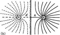
Figure 3.12b shows the simple case of a source A placed a short distance from an infinite plane wall. The effect of the solid boundary on the flow from the source is exactly represented by considering the effect of the image source A! reflected in the wall. The source pair has a long straight streamline, i. e. the vertical axis of symmetry, that separates the flows from the two sources and that may be replaced by a solid boundary without affecting the flow.

Solid boundaries and image systems

Solid boundaries and image systems

Solid boundaries and image systems

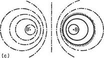
Figure 3.12c shows the flow in the cross-section of a vortex lying parallel to the axis of a circular duct. The circular duct wall can be replaced by the corresponding streamline in the vortex-pair system given by the original vortex В and its image B’.

Подпись: It can easily be shown that B' is a distance f-js from the centre of the duct on the diameter produced passing through B, where r is the radius of the duct and s is thedistance of the vortex axis from the centre of the duct.

More complicated contours require more complicated image systems and these are left until discussion of the cases in which they arise. It will be seen that Fig. 3.12a, which is the flow of Section 3.3.7, has an internal image system, the source being the image of a source at — oc and the sink being the image of a sink at +oc. This external source and sink combination produces the undisturbed uniform stream as has been noted above.

Flow of constant velocity in any direction

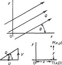
Consider the flow streaming past the jc, у axes at some velocity Q making angle 9 with the Ojc axis (Fig. 3.11). The velocity Q can be resolved into two components U and V parallel to the Ojc and Оу axes respectively where Q2 = U2 + V2 and tan# = V/U.

Again the stream function ф at a point P in the flow is a measure of the amount of fluid flowing past any line joining OP. Let the most convenient contour be OTP, T being given by (jc, 0). Therefore

Fig. 3.11

ф = flow across ОТ (going right to left, therefore negative in sign)

+ flow across TP

=— component of Q parallel to Oy times x + component of Q parallel to Ox times у rp = —Vx+Uy (3-16)

Lines of constant ф or streamlines are the curves

– Vx + Uy = constant

assigning a different value of ф for every streamline. Then in the equation V and U are constant velocities and the equation is that of a series of straight lines depending on the value of constant ф.

Here the velocity potential at P is a measure of the flow along any curve joining P to O. Taking OTP as the line of integration [T(x, O)]:

ф = flow along ОТ + flow along TP

Подпись: (3.17)

Flow of constant velocity in any direction

= Vx + Vy ф = Ux+ Vy

Example 3.1 Interpret the flow given by the stream function (units: m2 s ‘)

ф = 6x + 12у

The constant velocity in the horizontal direction = ^ = +12ms-1

dy

The constant velocity in the vertical direction =-^ = -6ms_I

ox

Therefore the flow equation represents uniform flow inclined to the Ox axis by angle $ where tan# = —6/12, i. e. inclined downward.

The speed of flow is given by

Q = ч/б2 + 122 = 7l80ms-1

Flow of constant velocity parallel to Oy axis

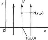
Consider flow streaming past the Ox, Oy axes at velocity Vparallel to Oy (Fig. 3.10). Again by definition the stream function ip at a point P(x, y) in the flow is given by the

Flow of constant velocity parallel to Oy axis

Fig. 3.10 amount of fluid crossing any curve between О and P. For convenience take OTP where T is given by (jc, 0). Then

ф = flow across ОТ + flow across TP = —Vx + 0

Note here that when going from О towards T the flow appears from the right and disappears to the left and therefore is of negative sign, i. e.

ip = – Vx (3.14)

The streamlines being lines of constant ф are given by jc = —ф/V and are parallel to Оу axis.

Again consider flow streaming past the Ojc, Оу axes with velocity V parallel to the Оу axis (Fig. 3.10). Again, taking the most convenient boundary as OTP where T is given by (jc, 0)

ф = flow along ОТ + flow along TP = 0 +Vy

Therefore

ф=Уу (3.15)

The lines of constant velocity potential, ф (equipotentials), are given by Vy = constant, which means, since V is constant, lines of constant y, are lines parallel to Ojc axis.