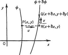
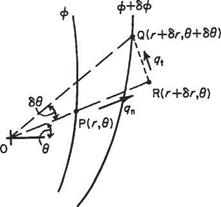
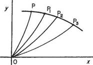
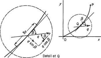
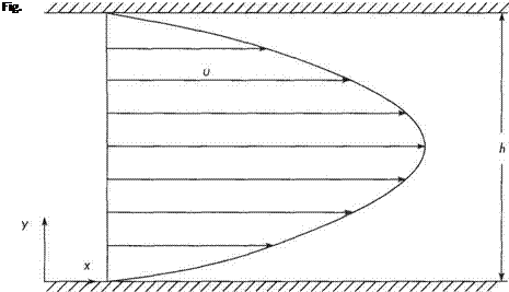
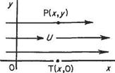
The simplest example of this type of flow, illustrated in Fig. 2.32, is generated by uniform flow impinging perpendicularly on an infinite plane. The flow divides equally about a stagnation point (strictly a line). The velocity field for the corresponding inviscid potential flow (see Chapter 3) is
и = ax v = —ay where a is a const. (2.111)
The real viscous flow must satisfy the no-slip condition at the wall – as shown in Fig. 2.32 – but the potential flow may offer some hints on seeking the full viscous solution.
This special solution is of particular interest for aerodynamics. All twodimensional stagnation flows behave in a similar way near the stagnation point. It can therefore be used as the starting solution for boundary-layer calculations in the case of two-dimensional bodies with rounded noses or leading edges (see Example 2.4). There is also an equivalent axisymmetric stagnation flow.
The approach used to find a solution to the two-dimensional Navier-Stokes Eqns (2.92) and (2.93) is to aim to reduce the equations to an ordinary differential equation. This is done by assuming that, when appropriately scaled, the non-dimensional
Fig. 2.32 Stagnation-zone flow field velocity profile remains the same shape throughout the flow field. Thus the nature of the flow field suggests that the normal velocity component is independent of x, so that
v = -/00 (2-112)
where f(y) is a function of у that has to be determined. Substitution of Eqn (2.112) into the continuity Eqn (2.93) gives
= /’ O’) і integrate to get и = xf{y) (2.113)
where ()’ denotes differentiation with respect to y. The constant of integration in Eqn (2.113) is equivalently zero, as u — v — 0 at x = 0 (the stagnation point), and was therefore omitted.
For a potential flow the Bernoulli equation gives
P + ^p(j£+_£) =Po – (2-114)
a2*2+o2.y2
So for the full viscous solution we will try the form:
Po-P = p^[^ + f(y)], (2.115)
where F(y) is another function of y. If the assumptions (2.112) and (2.115) are incorrect, we will fail in our objective of reducing the Navier-Stokes equations to ordinary differential equations.
Simplifying these two equations gives


/2 _//" = a2 + vfn 1
In its present form Eqn (2.118) contains both a and v, so that / depends on these parameters as well as being a function of y. It is desirable to derive a universal form of Eqn (2.118), so that we only need to solve it once and for all. We attempt to achieve this by scaling the variables /(y) and y, i. e. by writing
 f{y) = 0ф(т]), 77 = ay
where a and /3 are constants to be determined by substituting Eqn (2.122) into Eqn (2.118). Noting that
d/ drj йф,
/=5TdA; *
Eqn (2.118) thereby becomes
а2(32фа – а2(32фф" = a2 + (2.123)
Thus providing
a2 ft2 = a2 = va3 в, implying a = /a/v, /3 = fav (2.124)
they can be cancelled as common factors and Eqn (2.124) reduces to the universal form:
 ф’" + фф"-ф’2 + 1=0
with boundary conditions
0(0) = Ф'( 0) = 0, ф'( oo) = 1
In fact, ф’ = u! Ue where Ue = ax the velocity in the corresponding potential flow found when 77 —> oc. It is plotted in Fig. 2.33. We can regard the point at which ф’ = 0.99 as marking the edge of the viscous region. This occurs at 77 ~ 2.4. This viscous region can be regarded as the boundary layer in the vicinity of the stagnation point (note, though, no approximation was made to obtain the solution). Its thickness does not vary with x and is given by
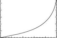

Fig. 2.33
Example 2.4 Calculating the boundary-layer thickness in the stagnation zone at the leading edge.
We will estimate the boundary-layer thickness in the stagnation zone of (i) a circular cylinder of 120 mm diameter in a wind-tunnel at a flow speed of 20m/s; and (ii) the leading-edge of a Boeing 747 wing with a leading-edge radius of 150 mm at a flight speed of 250 m/s.
For a circular cylinder the potential-flow solution for the tangential velocity at the surface is given by 2UX sin ф (see Eqn (3.44)). Therefore in Case (i) in the stagnation zone, x = R sin ф ~ Кф, so the velocity tangential to the cylinder is
Ut a 2ихф = 2% Rф
JV
X
Therefore, as shown in Fig. 2.34, if we draw an analogy with the analysis in Section 2.10.3 above, a = 21/oJR = 2 x 20/0.06 = 666.7 sec-1. Thus from Eqn (2.126), given that for air the kinematic viscosity, v ~ 15 x 10-6 m[7]/s,
For the aircraft wing in Case (ii) we regard the leading edge as analogous locally to a circular cylinder and follow the same procedure as for Case (i). Thus R = 150 mm = 0.15 m and U0о = 250m/s, so in the stagnation zone, a = 2UaJR = 2 x 250/0.15 = 3330sec-1 and
These results underline just how thin the boundary layer is! A point that will be taken up in Chapter 7.
Fig. 2.34
Exercises
1 Continuity Equation for axisymmetric flow
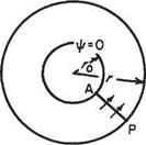
(a) Consider an axisymmetric flow field expressed in terms of the cylindrical coordinate system (г, <f>, z) where all flow variables are independent of the azimuthal angle ф. For example, the axial flow over a body of revolution. If the velocity components (m, w) correspond to the coordinate directions (r, z) respectively, show that the continuity equation is given by
(b) Show that the continuity equation can be automatically satisfied by a stream – function ф of a form such that
(b) Show that the continuity equation can be automatically satisfied by a stream- function ф of a form such that
3
Transport equation for contaminant in two-dimensional flow field In many engineering applications one is interested in the transport of a contaminant by the fluid flow. The contaminant could be anything from a polluting chemical to particulate matter. To derive the governing equation one needs to recognize that, provided that the contaminant is not being created within the flow field, then the mass of contaminant is conserved. The contaminant matter can be transported by two distinct physical mechanisms, namely convection and molecular diffusion. Let C be the concentration of contaminant (i. e. mass per unit volume of fluid), then the rate of transport of contamination per unit area is given by
where і and j are the unit vectors in the x and у directions respectively, and T> is the diffusion coefficient (units m2js, the same as kinematic viscosity).
Note that diffusion transports the contaminant down the concentration gradient (i. e. the transport is from a higher to a lower concentration) hence the minus sign. It is analogous to thermal conduction.
(a) Consider an infinitesimal rectangular control volume. Assume that no contaminant is produced within the control volume and that the contaminant is sufficiently dilute to leave the fluid flow unchanged. By considering a mass balance for the control volume, show that the transport equation for a contaminant in a twodimensional flow field is given by
(b) Why is it necessary to assume a dilute suspension of contaminant? What form would the transport equation take if this assumption were not made? Finally, how could the equation be modified to take account of the contaminant being produced by a chemical reaction at the rate of mc per unit volume.
4 Euler equations for axisymmetric flow
(a) for the flow field and coordinate system of Ex. 1 show that the Euler equations (inviscid momentum equations) take the form:
5 The Navier-Stokes equations for two-dimensional axisymmetric flow
(a) Show that the strain rates and vorticity for an axisymmetric viscous flow like that
described in Ex. 1 are given by:
[Hint: Note that the azimuthal strain rate is not zero. The easiest way to determine it is to recognize that in + ёфф + izz = 0 must be equivalent to the continuity equation.]
(b) Hence show that the Navier-Stokes equations for axisymmetric flow are given by /du du ди dp /cP’u Іди и д2u
рді + ид? + кЫ=Р8г~Ъ? + рд^ + ~г’дг~^ + Ъ?)
/dw dw dw dp /d^w 1 dw d2w
РШ + u^ + wfc)=p8z-fc + pd*+7fr + d*)
6 Euler equations for two-dimensional flow in polar coordinates
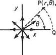
(a) For the two-dimensional flow described in Ex. 2 show that the Euler equations
(inviscid momentum equations) take the form:
|
(du du v du
|
|
, dp
|
|
РЬ+ид~г+-гдф-
|
r J
|
•|<fc
$
II
|
|
/dv dv v dv
|
uv
|
1 dp
|
|
pdt+ дг + гдф +
|
TJ
|
= р8ф ~ ~гдф
|
[Hints: (i) The momentum components perpendicular to and entering and leaving the side faces of the elemental control volume have small components in the radial direction that must be taken into account; likewise (ii) the pressure forces acting on these faces have small radial components.]
7 Show that the strain rates and vorticity for the flow and coordinate system of Ex. 6 are given by:
. _ du. _ 1 dv и
= Єфф = ~гдф + ~г
. _ 1 (®v v 1 ®u c _ 1 5v v
1гф = 2 дг~~г+~гдфГ ^ = ^дф~д? + г
[Hint: (і) The angle of distortion (/3) of the side face must be defined relative to the line joining the origin О to the centre of the infinitesimal control volume.]
8 (a) The flow in the narrow gap (of width A) between two concentric cylinders of length L with the inner one of radius R rotating at angular speed и can be approximated by the Couette solution to the Navier-Stokes equations. Hence show that the torque T and power P required to rotate the shaft at a rotational speed of wrad/s are given by
2npu>R3L Ітціш2 R? L
T= A ’ P = A
9 Axisymmetric stagnation-point flow
Carry out a similar analysis to that described in Section 2.10.3 using the axisymmetric form of the Navier-Stokes equations given in Ex. 5 for axisymmetric stagnation – point flow and show that the equivalent to Eqn (2.118) is
ф’" + 2 фф" – фа + 1=0
where ф’ denotes differentiation with respect to the independent variable ( = sjajvz and ф is defined in exactly the same way as for the two-dimensional case.
![]()


 m дф
m дф


