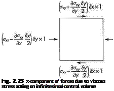
Restricting our derivation to two-dimensional flow, Eqn (2.87) with (2.72a) and (2.73) gives
So the right-hand side of the momentum Eqns (2.66a) becomes
The right-hand side of (2.66b) can be dealt with in a similar way. Thus the momentum equations (2.66a, b) can be written in the form
 (2.92a)
(2.92b)
This form of the momentum equations is known as the Navier-Stokes equations for two-dimensional flow. With the inclusion of the continuity equation
 du dv
du dv
d7x + d-y = Q we now have three governing equations for three unknown flow variables u, v, p.
The Navier-Stokes equations for three-dimensional incompressible flows are given below:
1.9 Properties of the Navier-Stokes equations
At first sight the Navier-Stokes equations, especially the three-dimensional version, Eqns (2.95), may appear rather formidable. It is important to recall that they are nothing more than the application of Newton’s second law of motion to fluid flow.
For example, the left-hand side of Eqn (2.95a) represents the total rate of change of the x component of momentum per unit volume. Indeed it is often written as:
 Du D д д д d
’Di where msm+uTx+%+wdz
is called the total or material derivative. It represents the total rate of change with time following the fluid motion. The left-hand sides of Eqns (2.95b, c) can be written in a similar form. The three terms on the right-hand side represent the x components of body force, pressure force and viscous force respectively acting on a unit volume of fluid.
The compressible versions of the Navier-Stokes equations plus the continuity equation encompass almost the whole of aerodynamics. To be sure, applications involving combustion or rarified flow would require additional chemical and physical principles, but most of aerodynamics is contained within the Navier-Stokes equations. Why, then, do we need the rest of the book, not to mention the remaining vast, ever-growing, literature devoted to aerodynamics? Given the power of modem computers, could we not merely solve the Navier-Stokes equations numerically for any aerodynamics application of interest? The short answer is no! Moreover, there is no prospect of it ever being possible. To explain fully why this is so is rather difficult. We will, nevertheless, attempt to give a brief indication of the nature of the problem.
Let us begin by noting that the Navier-Stokes equations are a set of partial differential equations. Few analytical solutions exist that are useful in aerodynamics. (The most useful examples will be described in Section 2.10.) Accordingly, it is essential to seek approximate solutions. Nowadays, it is often possible to obtain very accurate numerical solutions by using computers. In many respects these can be regarded almost as exact solutions, although one must never forget that computergenerated solutions are subject to error. It is by no means simple to obtain such numerical solutions of the Navier-Stokes equations. There are two main sources of difficulty. First, the equations are nonlinear. The nonlinearity arises from the left – hand sides, i. e. the terms representing the rate of change of momentum – the so-called inertial terms. To appreciate why these terms are nonlinear, simply note that when you take a term on the right-hand side of the equations, e. g. the pressure terms, when the flow variable (e. g. pressure) is doubled the term is also doubled in magnitude. This is also true for the viscous terms. Thus these terms are proportional to the unknown flow variables, i. e. they are linear. Now consider a typical inertial term, say иди/дх. This term is plainly proportional to u2 and not u, and is therefore nonlinear. The second source of difficulty is more subtle. It involves the complex effects of viscosity.
In order to understand this second point better, it is necessary to make the Navier – Stokes equations non-dimensional. The motivation for working with non-dimensional variables and equations is that it helps to make the theory scale-invariant and accordingly more universal (see Section 1.4). In order to fix ideas, let us consider the air flowing at speed U00 towards a body, a circular cylinder or wing say, of length L. See Fig. 2.29. The space variables x, y, and z can be made nondimensional by dividing by
L. L/Uqc can be used as the reference time to make time non-dimensional. Thus we introduce the non-dimensional coordinates
X = x/L, Y = y/L, Z = z/L, and T = lU/L (2.97)
Uoo can be used as the reference flow speed to make the velocity components dimensionless and pU^ (c. f. Bernoulli equation Eqn (2.16)) used as the reference
U.
Fig. 2.29
pressure. (For incompressible flow, at least, only pressure difference is of significance and not the absolute value of the pressure.) This allows us to introduce the following non-dimensional flow variables:
U = u/Uoo, V = v/Ux, W = w/Uoo, and P=p/(pU20O) (2.98)
If, by writing x — XL etc. the non-dimensional variables given in Eqns (2.97) and
(2.98) are substituted into Eqns (2.94) and (2.95) with the body-force terms omitted, we obtain the Navier-Stokes equations in the form:
|
dU dV dW dX + dY + ~dZ ~
|
(2.99)
|
|
DU
|
дР 1 /&U &U ^L/x
|
(2.100a)
|
|
DT ~
|
dX + Re KdX2 + dY2 + dZ2)
|
|
DV
|
дР 1 t&V &V ^Fx
|
(2.100b)
|
|
DT~
|
dY + Re KdX2 + dY2 + dZ2)
|
|
DW
|
дР 1 f&W &W ^IFx
|
(2.100c)
|
|
DT ~
|
dZ + ReKdX2 + dY2 + dZ2)
|
where the short-hand notation (2.96) for the material derivative has been used. A feature of Eqns (2.100) is the appearance of the dimensionless quantity known as the Reynolds number.
Re = ^°-h (2.Ю1)
From the manner in which it has emerged from making the Navier-Stokes equations dimensionless, it is evident that the Reynolds number (see also Section 1.4) represents the ratio of the inertial to the viscous terms (i. e. the ratio of rate of change of momentum to the viscous force). It would be difficult to overstate the significance of Reynolds number for aerodynamics.
It should now be clear from Eqns (2.99) and (2.100) that if one were to calculate the non-dimensional flow field for a given shape – a circular cylinder, for example – the overall flow pattern obtained would depend on the Reynolds number and, in the case of unsteady flows, on the dimensionless time T. The flow around a circular cylinder is a good example for illustrating just how much the flow pattern can change over a wide range of Reynolds number. See Section 7.5 and Fig. 7.14 in particular. Incidentally, the simple dimensional analysis carried out above shows that it is not always necessary to solve equations in order to extract useful information from them.
For high-speed flows where compressibility becomes important the absolute value of pressure becomes significant. As explained in Section 2.3.4 (see also Section 1.4), this leads to the appearance of the Mach number, M (the ratio of the flow speed to the speed of sound), in the stagnation pressure coefficient. Thus, when compressibility
becomes important (see Section 2.3.4), Mach number becomes a second dimensionless quantity characterizing the flow field.
The Navier-Stokes equations are deceptively simple in form, but at high Reynolds numbers the resulting flow fields can be exceedingly complex even for simple geometries. This is basically a consequence of the behaviour of the regions of vortical flow at high Reynolds number. Vorticity can only be created in a viscous flow and can be regarded as a marker for regions where the effects of viscosity are important in some sense.
For engineering applications of aerodynamics the Reynolds numbers are very large, values well in excess of 106 are commonplace. Accordingly, one would expect that to a good approximation one could drop the viscous terms on the right-hand side of the dimensionless Navier-Stokes Eqns (2.100). In general, however, this view would be mistaken and one never achieves a flow field similar to the inviscid one no matter how high the Reynolds number. The reason is that the regions of non-zero vorticity where viscous effects cannot be neglected become confined to exceedingly thin boundary layers adjacent to the body surface. As Re —> oc the boundary-layer thickness, 6 —► 0. If the boundary layers remained attached to the surface they would have little effect beyond giving rise to skin-friction drag. But in all real flows the boundary layers separate from the surface of the body, either because of the effects of an adverse pressure gradient or because they reach the rear of the body or its trailing edge. When these thin regions of vortical flow separate they form complex unsteady vortex-like structures in the wake. These take their most extreme form in turbulent flow which is characterized by vortical structures with a wide range of length and time scales.
As we have seen from the discussion given above, it is not necessary to solve the Navier-Stokes equations in order to obtain useful information from them. This is also illustrated by following example:
Example 2.3 Aerodynamic modelling
 |
 |
Let us suppose that we are interested carrying out tests on a model in a wind-tunnel in order to study and determine the aerodynamic forces exerted on a motor vehicle travelling at normal motorway speeds. In this case the speeds are sufficiently low to ensure that the effects of compressibility are negligible. Thus for a fixed geometry the flow field will be characterized only by Reynolds number.[6] In this case we can use Ux, the speed at which the vehicle travels (the air speed in the wind-tunnel working section for the model) as the reference flow speed, and L can be the width or length of the vehicle. So the Reynolds number Re = pUxLjfi. For a fixed geometry it is clear from Eqns (2.99) and (2.100) that the non-dimensional flow variables, U, V, W, and P are functions only of the dimensionless coordinates X, Y, Z, T, and the dimensionless quantity, Re. In a steady flow the aerodynamic force, being an overall characteristic of the flow field, will not depend on X, Y, Z, or T. It will, in fact, depend only on Re. Thus if we make an aerodynamic force, drag (D) say, dimensionless, by introducing a force (i. e. drag) coefficient defined as
(see Section 1.5.2 and noting that here we have used I? in place of area S) it should be clear that
 Cd = F(Re) i. e. a function of Re only
If we wish the model tests to produce useful information about general characteristics of the prototype’s flow field, in particular estimates for its aerodynamic drag, it is necessary for the model and prototype to be dynamically similar, i. e. for the forces to be scale invariant. It can be seen from Eqn (2.103) that this can only be achieved provided
where suffices m and p denote model and prototype respectively.
It is not usually practicable to use any other fluid but air for the model tests. For standard wind-tunnels the air properties in the wind-tunnel are not greatly different from those experienced by the prototype. Accordingly, Eqn (2.104) implies that
 (2.105)
Thus, if we use a 1/5-scale model, Eqn (2.105) implies that Um = 5Up. So a prototype speed of lOOkm/hr (c. 30m/s) implies a model speed of 500km/hr (c. 150m/s). At such a model speed compressibility effects are no longer negligible. This illustrative example suggests that, in practice, it is rarely possible to achieve dynamic similarity in aerodynamic model tests using standard wind-tunnels. In fact, dynamic similarity can usually only be achieved in aerodynamics by using very large and expensive facilities where the dynamic similarity is achieved by compressing the air (thereby increasing its density) and using large models.
In this example we have briefly revisited the material covered in Section 1.4. The objective was to show how the dimensional analysis of the Navier-Stokes equations (effectively the exact governing equations of the flow field) could establish more rigorously the concepts introduced in Section 1.4.



 (2.92a)




 da dp _ dv du dr dr dx dy



 ( dv dv l’{ua-x+”Ty)6xlyxl
 ‘~lf)
‘~lf)


 бух 1
бух 1