Category Aerodynamics for Engineering Students

Velocity components in terms of у/

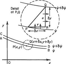
(a) In Cartesian coordinates Let point P(x, y) be on the streamline AB in Fig. 2.18a of constant ip and point Q(x + 8x, у + 6y) be on the streamline CD of constant ip + Sip. Then from the definition of stream function, the amount of fluid flowing across any path between P and Q = Sip, the change of stream function between P and Q.

The most convenient path along which to integrate in this case is PRQ, point R being given by the coordinates (x + 6x, y). Then the flow across PR = —v6x (since the flow is from right to left and thus by convention negative), and that across RQ = ибу. Therefore, total flow across the line PRQ is

Подпись: (2.55)Sip = ибу — v6x

Velocity components in terms of у/

Now ip is a function of two independent variables x and у in steady motion, and thus

Velocity components in terms of у/

Fig. 2.18a дф/дх and дф/ду being the partial derivatives with respect to л: and у respectively. Then, equating terms:

и = дф/ду (2.56a)

and

v = —дф/дх (2.56b)

these being the velocity components at a point x, у in a flow given by stream function ф.

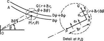
(b) In polar coordinates Let the point P(r, 6) be on the streamline AB (Fig. 2.18b) of constant ф, and point Q(r + 6r, 6 + 66) be on the streamline CD of constant ф + 6ф. The velocity components are qn and qu radially and tangentially respectively. Here the most convenient path of integration is PRQ where OP is produced to R so that PR = 6r, i. e. R is given by ordinates (r + 6r, 6). Then

6ф — – qt6r + qn(r + 6r)66 = —qt6r + qnr66 + qn6r66

To the first order of small quantities:

6ф = —qi6r + qar66 (2-57)

Velocity components in terms of у/

Velocity components in terms of у/

дф


Velocity components in terms of у/

Fig. 2.19

But here ф is a function of (г, в) and again

r, дф дф or дв

(2.58)

and equating terms in Eqns (2.57) and (2.58)

дф

(2.58a)

І дф

qn=~r~5§

(2.58b)

these being velocity components at a point r, 0 in a flow given by stream function ф.

In general terms the velocity q in any direction л is found by differentiating the stream function ф partially with respect to the direction n normal to q where n is taken in the anti-clockwise sense looking along q (Fig. 2.19):

дф

The streamline

The streamline The streamline

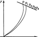
From the statement above, ipp is the flow across the line OP. Suppose there is a point Pi close to P which has the same value of stream function as point P (Fig. 2.17). Then the flow across any line OPi equals that across OP, and the amount of fluid flowing into area OPP^ across OP equals the amount flowing out across OP^ Therefore, no fluid crosses line PPi and the velocity of flow must be along, or tangential to, PP).

The streamline

Fig. 2.17

All other points P2, P3, etc. which have a stream function equal in value to that of P have, by definition, the same flow across any lines joining them to O, so by the same argument the velocity of the flow in the region of Рь P2, P3, etc. must be along PPi, P2, P3, etc., and no fluid crosses the line PPb P2,… ,P„. Since i/y, = ipPl = фр}=фр = constant, the line PPb P2,… P„, etc. is a line of constant ip and is called a streamline. It follows further that since no flow can cross the line PP„ the velocity along the line must always be in the direction tangential to it. This leads to the two common definitions of a streamline, each of which indirectly has the other’s meaning. They are:

A streamline is a line of constant ip

and/or

A streamline is a line of fluid particles, the velocity of each particle being tangential to the line (see also Section 2.1.2).

It should be noted that the velocity can change in magnitude along a streamline but by definition the direction is always that of the tangent to the line.

The stream function and streamline

1.3.2 The stream function у/

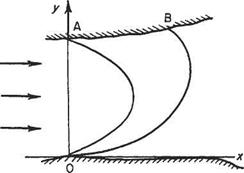
Imagine being on the banks of a shallow river of a constant depth of 1 m at a pos­ition О (Fig. 2.14) with a friend directly opposite at A, 40 m away. Mathematically

The stream function and streamline

Fig. 2.14

the bank can be represented by the Ox axis, and the line joining you to your friend at A the Оу axis in the two-coordinate system. Now if the stream speed is 2ms-1 the amount of water passing between you and your friend is 40 x 1 x 2 = 80 m3 s-1 and this is the amount of water flowing past any point anywhere along the river which could be measured at a weir downstream. Suppose you now throw a buoyant rope to your friend who catches the end but allows the slack to fall in the river and float into a curve as shown. The amount of water flowing under the line is still 80 m3 s-1 no matter what shape the rope takes, and is unaffected by the configuration of the rope.

Suppose your friend moves along to a point В somewhere downstream, still holding his end of the line but with sufficient rope paid out as he goes. The volume of water passing under the rope is still only 80 m3 s-1 providing he has not stepped over a tributary stream or an irrigation drain in the bank. It follows that, if no water can enter or leave the stream, the quantity flowing past the line will be the same as before and furthermore will be unaffected by the shape of the line between О and B. The amount or quantity of fluid passing such a line per second is called the stream function or current function and it is denoted by ф.

The stream function and streamline

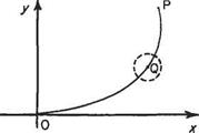
Consider now a pair of coordinate axes set in a two-dimensional air stream that is moving generally from left to right (Fig. 2.15). The axes are arbitrary space references and in no way interrupt the fluid streaming past. Similarly the line joining О to a point P in the flow in no way interrupts the flow since it is as imaginary as the reference axes Ox and Оу. An algebraic expression can be found for the line in x and y.

The stream function and streamline

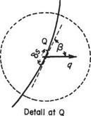
Let the flow past the line at any point Q on it be at velocity q over a small length Ss of line where direction of q makes angle /3 to the tangent of the curve at Q. The component of the velocity q perpendicular to the element Ss is q sin Q and therefore, assuming the depth of stream flow to be unity, the amount of fluid crossing the element of line Ss is q sin /3 x Ss x 1 per second. Adding up all such quantities crossing similar elements along the line from О to P, the total amount of flow past the line (sometimes called flux) is

which is the line integral of the normal velocity component from О to P.

The stream function and streamline

If this quantity of fluid flowing between О and P remains the same irrespective of the path of integration, i. e. independent of the curve of the rope then fop q sin /3 dj is called the stream function of P with respect to О and

Note: it is implicit that V’o = 0.

Sign convention for stream functions

It is necessary here to consider a sign convention since quantities of fluid are being considered. When integrating the cross-wise component of flow along a curve, the component can go either from left to right, or vice versa, across the path of integra­tion (Fig. 2.16). Integrating the normal flow components from О to P, the flow components are, looking in the direction of integration, either (a) from left to right or (b) from right to left. The former is considered positive flow whilst the latter is negative flow. The convention is therefore:

Flow across the path of integration is positive if, when looking in the direction of integration, it crosses the path from left to right.

The equation of continuity in polar coordinates

Подпись: ( d(pqn) 6r ( 8r ( d(pqn) 8r ( 8r Vb—aTi) [r-2Г~ {"Ь+-6Г2) V+2)

A corresponding equation can be found in the polar coordinates r and 6 where the velocity components are qn and qt radially and tangentially. By carrying out a similar development for the accumulation of fluid in a segmental elemental box of space, the equation of continuity corresponding to Eqn (2.44) above can be found as follows. Taking the element to be at P(r, 6) where the mass flow is pq per unit length (Fig. 2.13), the accumulation per second radially is:

The equation of continuity in polar coordinates

The equation of continuity in polar coordinates

Fig. 2.13 Rectangular element at P (г, в) in a system of polar coordinates and accumulation per second tangentially is:


(2.49)


The equation of continuity in polar coordinates

(2.50)


The equation of continuity in polar coordinates

and this by the previous argument equals the rate of change of mass within the region of space

д(ргбгбв)

dt

(2.51)

Equating (2.50) and (2.51) gives:

РЧ n dp d(pqn) 1 d(pq{) r dt dr r d0

(2.52)

Hence for steady flow

d{prqn) d{pql) dr de

(2.53)

and the incompressible equation in this form becomes:

4n dqn 1 dql r dr r d0

(2.54)

The equation of continuity or conservation of mass

Consider a typical elemental control volume like the one illustrated in Fig. 2.8. This is a small rectangular region of space of sides 6x, 6y and unity, centred at the point P(x, y) in a fluid motion which is referred to the axes Ox, Oy. At P(x, y) the local velocity components are и and v and the density p, where each of these three quantities is a function of x, у and t (Fig. 2.12). Dealing with the flow into the box in the Ox direction, the amount of mass flowing into the region of space per second through the left-hand vertical face is:

mass flow per unit area x area

i. e.

The equation of continuity or conservation of mass(2.38)

The amount of mass leaving the box per second through the right-hand vertical face is:

The equation of continuity or conservation of mass(2.39)

The accumulation of mass per second in the box due to the horizontal flow is the difference of Eqns (2.38) and (2.39), i. e.

The equation of continuity or conservation of mass(2.40)

Similarly, the accumulation per second in the Oy direction is

The equation of continuity or conservation of mass

The equation of continuity or conservation of mass

(2.41)

The equation of continuity or conservation of mass

so that the total accumulation per second is

As mass cannot be destroyed or created, Eqn (2.42) must represent the rate of change of mass of the fluid in the box and can also be written as

d{p x volume)
dt

but with the elementary box having constant volume (8x 8y x 1) this becomes

Подпись: (2.43)dp

aiSx6y^1

Equating (2.42) and (2.43) gives the general equation of continuity, thus:

Подпись: (2.44)dp d{pu) d(pv) dt dx dy

Подпись: dp dp dp (du dv ~dt + Ud-x+VYy + Pd~x + -dy, Подпись: = 0 Подпись: (2.45)

This can be expanded to:

and if the fluid is incompressible and the flow steady the first three terms are all zero since the density cannot change and the equation reduces for incompressible flow to

Подпись: (2.46)du dv d~x + d~y~

Подпись: du dx Подпись: dv dy

This equation is fundamental and important and it should be noted that it expresses a physical reality. For example, in the case given by Eqn (2.46)

This reflects the fact that if the flow velocity increases in the x direction it must decrease in the у direction.

For three-dimensional flows Eqns (2.45) and (2.46) are written in the forms:

Подпись: (2.47a) (2.47b) dp dp dp dp (du dv dw

m + ufc+vdi+wte+p(fc+di+te)=0

Подпись:du dv dw dx dy dz

Fluid acceleration

Подпись: andПодпись: (2.34)

Подпись: , , , ди ,du u + 8u = н + —<5x + —<5y ox dy Подпись: . dv dv v + <5v = v + — 8x + — 8y ox oy

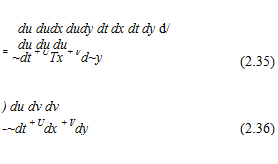
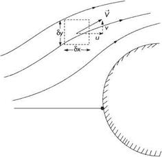
The equation of acceleration of a fluid mass is rather different from that of a vehicle, for example, and a note on fluid acceleration follows. Let a fluid particle move from P to Q in time 8t in a two-dimensional flow (Fig. 2.11). At the point P(x, y) the velocity components are и and v. At the adjacent point Q(x + 6x, у + 8y) the velocity components are и + би and v + 6v, i. e. in general the velocity component has changed in each direction by an increment 8u or 8v. This incremental change is the result of a spatial displacement, and as и and v are functions of x and у the velocity components at Q are

The component of acceleration in the Ox direction is thus

Подпись:Подпись:Подпись: d td(M + 8u)

and in the Oy direction

The change in other flow variables, such as pressure, between points P and Q may be dealt with in a similar way. Thus, if the pressure takes the value p at P, at Q it takes the value

Component velocities

In general the local velocity in a flow is inclined to the reference axes O. v, Oy and it is usual to resolve the velocity vector v (magnitude q) into two components mutually at right-angles.

Component velocities

Fig. 2.8 An infinitesimal control volume in a typical two-dimensional flow field

Component velocities

Fig. 2.9

In a Cartesian coordinate system let a particle move from point P(x, y) to point Q(jc + 8x, у + 6y), a distance of 6s in time St (Fig. 2.9). Then the velocity of the particle is

.. 6s ds lim— = ~r = q s-> о 6t d /

Going from P to Q the particle moves horizontally through 8x giving the horizontal velocity и = dx/dt positive to the right. Similarly going from P to Q the particle moves vertically through 6y and the vertical velocity v = dy/dt (upwards positive). By geometry:

(&)2 = (&c)2 + («y)2

Thus

q2 = i? + v2

and the direction of q relative to the jc-axis is a = tan-1 (v/k).

In a polar coordinate system (Fig. 2.10) the particle moves distance 6s from P(r, в) to Q(r + 8r,6 + 69) in time St. The component velocities are:

radially (outwards positive) qn = ^

d t

tangentially (anti-clockwise positive) qt = r^-

dt

Again

(8s)2 – (8rf + (r69)2

0 (r+8л,9-h 8 в)

Component velocities

Component velocities

Fig. 2.11

Thus

# = <& + £

and the direction of q relative to the radius vector is given by

/3 = tan-1 ^

Two-dimensional flow

Consider flow in two dimensions only. The flow is the same as that between two planes set parallel and a little distance apart. The fluid can then flow in any direction between and parallel to the planes but not at right angles to them. This means that in the subsequent mathematics there are only two space variables, v and у in Cartesian (or rectangular) coordinates or r and в in polar coordinates. For convenience, a unit length of the flow field is assumed in the z direction perpendicular to x and y. This simplifies the treatment of two-dimensional flow problems, but care must be taken in the matter of units.

In practice if two-dimensional flow is to be simulated experimentally, the method of constraining the flow between two close parallel plates is often used, e. g. small smoke tunnels and some high-speed tunnels.

To summarize, two-dimensional flow is fluid motion where the velocity at all points is parallel to a given plane.

We have already seen how the principles of conservation of mass and momentum can be applied to one-dimensional flows to give the continuity and momentum equations (see Section 2.2). We will now derive the governing equations for two-dimensional flow. These are obtained by applying conservation of mass and momentum to an infinitesimal rectangular control volume – see Fig. 2.8.

The incompressibility assumption

As a first step in calculating the stagnation pressure coefficient in compressible flow we use Eqn (1.6d) to rewrite the dynamic pressure as follows:

(2.30)

where M is Mach number.

When the ratio of the specific heats, 7, is given the value 1.4 (approximately the value for air), the stagnation pressure coefficient then becomes

Подпись: (2.31)po-p _ 1 fpo 1

Pa Q. lpM2 0.1MP p

Now

m = [1 + l M217/2 (Eqn (6.16a)) P 5

Подпись: 75 1/1 ъЛ + 222! 5MПодпись: + •

Подпись: 10 The incompressibility assumption Подпись: ' 753 1 Л 1 + 2223! І5М Подпись: ’ 7531 1 /1 . + 22224! І5М

Expanding this by the binomial theorem gives

Then

Подпись: c =J0- pa 1M2

Подпись: 40 400 16 000 Подпись: + -
The incompressibility assumption

(?-*)

Подпись: (2.32)M2 M4 M6 + 4 + 40 + 1600

It can be seen that this will become unity, the incompressible value, at M = 0. This is the practical meaning of the incompressibility assumption, i. e. that any velocity changes are small compared with the speed of sound in the fluid. The result given in Eqn (2.32) is the correct one, that applies at all Mach numbers less than unity. At supersonic speeds, shock waves may be formed in which case the physics of the flow are completely altered.

Table 2.1 shows the variation of CPo with Mach number. It is seen that the error in assuming Cpt — 1 is only 2% at M — 0.3 but rises rapidly at higher Mach numbers, being slightly more than 6% at M = 0.5 and 27.6% at M = 1.0.

Table 2.1 Variation of stagnation pressure coefficient with Mach numbers less than unity

M 0 0.2 0.4 0.6 0.7 0.8 0.9 1.0

CP0 1 1.01 1.04 1.09 1.13 1.16 1.217 1.276

It is often convenient to regard the effects of compressibility as negligible if the flow speed nowhere exceeds about 100 m s-1. However, it must be remembered that this is an entirely arbitrary limit. Compressibility applies at all flow speeds and, therefore, ignoring it always introduces an error. It is thus necessary to consider, for each problem, whether the error can be tolerated or not.

In the following examples use will be made of the equation (1.6d) for the speed of sound that can also be written as

a = 4/7 RT

For air, with 7 = 1.4 and R = 287.3 J kg-1K-1 this becomes

Подпись: (2.33)a = 20.054/7 ms"1

where T is the temperature in K.

Example 2.1 The air-speed indicator fitted to a particular aeroplane has no instrument errors and is calibrated assuming incompressible flow in standard conditions. While flying at sea level in the ISA the indicated air speed is 950 km h-1. What is the true air speed?

950 kmh-1 = 264ms-1 and this is the speed corresponding to the pressure difference applied to the instrument based on the stated calibration. This pressure difference can therefore be calculated by

Po-p = Ap = – po^i

and therefore

p0-p = – x 1.226(264)2 = 42670Nm-2

The incompressibility assumption

Now

In standard conditions p = 101 325Nm 2. Therefore

Подпись:po _ 42670 p ~ 101 325

Therefore

1+ім2 = (1.421)2/7 = 1.106

^M2 = 0.106

M2 = 0.530 M = 0.728

The speed of sound at standard conditions is

a = 20.05(288)* = 340.3 m s-1

Therefore, true air speed = Ma = 0.728 x 340.3

248ms-1 = 891 km IT1

In this example, a = 1 and therefore there is no effect due to density, i. e. the difference is due entirely to compressibility. Thus it is seen that neglecting compressibility in the calibration has led the air-speed indicator to overestimate the true air speed by 59 km IT1.

The air-speed indicator: indicated and equivalent air speeds

A Pitot-static tube is commonly used to measure air speed both in the laboratory and on aircraft. There are, however, differences in the requirements for the two applica­tions. In the laboratory, liquid manometers provide a simple and direct method for


measuring pressure. These would be completely unsuitable for use on an aircraft where a pressure transducer is used that converts the pressure measurement into an electrical signal. Pressure transducers are also becoming more and more commonly used for laboratory measurements.

When the measured pressure difference is converted into air speed, the correct value for the air density should, of course, be used in Eqn (2.19). This is easy enough in the laboratory, although for accurate results the variation of density with the ambient atmospheric pressure in the laboratory should be taken into account. At one time it was more difficult to use the actual air density for flight measurements. This was because the air-speed indicator (the combination of Pitot-static tube and transducer) would have been calibrated on the assumption that the air density took the standard sea-level International Standard Atmosphere (ISA) value. The (incor­rect) value of air speed obtained from Eqn (2.19) using this standard value of pressure with a hypothetical perfect transducer is known as the equivalent air speed (EAS). A term that is still in use. The relationship between true and equivalent air speed can be derived as follows. Using the correct value of density, p, in Eqn (2.19) shows that the relationship between the measured pressure difference and true air speed, v, is

Подпись: (2.25)Ap = -pv2

whereas if the standard value of density, po = 1.226kg/m3, is used we find

The air-speed indicator: indicated and equivalent air speeds(2.26)

where ve is the equivalent air speed. But the values of Ap in Eqns (2.25) and (2.26) are the same and therefore

The air-speed indicator: indicated and equivalent air speeds(2.27)

or

Подпись:Подпись: (2.29)ve = vy/p/po

If the relative density a = p/po is introduced, Eqn (2.28) can be written as

ve vyfa

The term indicated air speed (IAS) is used for the measurement made with an actual (imperfect) air-speed indicator. Owing to instrument error, the IAS will normally differ from the EAS.

The following definitions may therefore be stated: IAS is the uncorrected reading shown by an actual air-speed indicator. Equivalent air speed EAS is the uncorrected reading that would be shown by a hypothetical, error-free, air-speed indicator. True air speed (TAS) is the actual speed of the aircraft relative to the air. Only when (7=1 will true and equivalent air speeds be equal. Normally the EAS is less than the TAS.

Formerly, the aircraft navigator would have needed to calculate the TAS from the IAS. But in modem aircraft, the conversion is done electronically. The calibration of the air-speed indicator also makes an approximate correction for compressibihty.