Referring back to Eqn (2.8), that expresses the conservation of momentum in algebraic form,
the first term is the internal energy of unit mass of the air, ^ v2 is the kinetic energy of unit mass and gz is the potential energy of unit mass. Thus, Bernoulli’s equation in this form is really a statement of the principle of conservation of energy in the absence of heat exchanged and work done. As a corollary, it applies only to flows where there is no mechanism for the dissipation of energy into some form not included in the above three terms. In aerodynamics a common form of energy dissipation is that due to viscosity. Thus, strictly the equation cannot be applied in this form to a flow where the effects of viscosity are appreciable, such as that in a boundary layer.
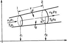
Conservation of energy implies that changes in energy, heat transferred and work done by a system in steady operation are in balance. In seeking an equation to represent the conservation of energy in the steady flow of a fluid it is useful to consider a length of stream tube, e. g. between sections 1 and 2 (Fig. 2.6), as
Fig. 2.6 Control volume for the energy equation
constituting the control surface of a ‘thermodynamic system’ or control volume. At sections 1 and 2, let the fluid properties be as shown.
Then unit mass of fluid entering the system through section will possess internal energy cyT, kinetic energy vj2 and potential energy gz, i. e.
(cvT + (2.9a)
Likewise on exit from the system across section 2 unit mass will possess energy
(cvT2 + у + gz^j (2.9b)
Now to enter the system, unit mass possesses a volume l/pi which must push against the pressure pi and utilize energy to the value of p x 1/pi pressure x (specific) volume. At exit P2/P2 is utilized in a similar manner.
In the meantime, the system accepts, or rejects, heat q per unit mass. As all the quantities are flowing steadily, the energy entering plus the heat transfer must equal the energy leaving.[5] Thus, with a positive heat transfer it follows from conservation of energy
rr. vf pi _ , V? P2 ,
cvT +-^4—— -gz +q = cvT2 + ^H——- hgz2
2 pi 2 p2
However, enthalpy per unit mass of fluid is cyT+р/р = cpT. Thus (cpT2 + у + gzij ~ (cpT + ^ + gz^j = q or in differential form
i(c, r + y + sS«,5a)=g (2.10)
For an adiabatic (no heat transfer) horizontal flow system, Eqn (2.10) becomes zero and thus
y2
cpT + — = constant (2-11)
The first law of thermodynamics requires that the gain in internal energy of a mass of gas plus the work done by the mass is equal to the heat supplied, i. e. for unit mass of gas with no heat transfer
But
Therefore, from Eqns (2.14) and (2.15)
=°
which on integrating gives
In p + 7 In ( — = constant
PJ
or
p = kp<
where к is a constant. This is the isentropic relationship between pressure and density, and has been replicated for convenience from Eqn (1.24).
The momentum equation for an incompressible fluid
Provided velocity and pressure changes are small, density changes will be very small, and it is permissible to assume that the density p is constant throughout the flow. With this assumption, Eqn (2.8) may be integrated as
ft? + ^ pv2 + pgz = constant
Performing this integration between two conditions represented by suffices 1 and 2 gives
P +^pv I + pg= 1 = P2 +^pv22 + pg=2
In the foregoing analysis 1 and 2 were completely arbitrary choices, and therefore the same equation must apply to conditions at any other points. Thus
 1 ? 1 ?
p + – pv~ + pgz = constant
This is Bernoulli’s equation for an incompressible fluid, i. e. a fluid that cannot be compressed or expanded, and for which the density is invariable. Note that Eqn (2.16) can be applied more generally to two – and three-dimensional steady flows, provided that viscous effects are neglected. In the more general case, however, it is important to note that Bernoulli’s equation can only be applied along a streamline, and in certain cases the constant may vary from streamline to streamline.
Conservation of momentum requires that the time rate of change of momentum in a given direction is equal to the sum of the forces acting in that direction. This is known as Newton’s second law of motion and in the model used here the forces concerned are gravitational (body) forces and the surface forces.
Consider a fluid in steady flow, and take any small stream tube as in Fig. 2.4. s is the distance measured along the axis of the stream tube from some arbitrary origin. A is the cross-sectional area of the stream tube at distance s from the arbitrary origin.
p, p, and v represent pressure, density and flow speed respectively.
A, p, p, and v vary with s, i. e. with position along the stream tube, but not with time since the motion is steady.
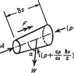
Now consider the small element of fluid shown in Fig. 2.5, which is immersed in fluid of varying pressure. The element is the right frustrum of a cone of length 6s, area A at the upstream section, area A + 6A on the downstream section. The pressure acting on one face of the element is p, and on the other face is p + (dp/ds)6s. Around
78s) (-4+8/1)
 
Fig. 2.5 The forces on the element
the curved surface the pressure may be taken to be the mean value p + (dp/ds)6s. In addition the weight W of the fluid in the element acts vertically as shown. Shear forces on the surface due to viscosity would add another force, which is ignored here.
As a result of these pressures and the weight, there is a resultant force F acting along the axis of the cylinder where F is given by
where a is the angle between the axis of the stream tube and the vertical.
From Eqn (2.5) it is seen that on neglecting quantities of small order such as (dpjds)6s6A and cancelling,
 F = —^f~A 6s — pg A (6s) cos a F = —^f~A 6s — pg A (6s) cos a
since the gravitational force on the fluid in the element is pg A 6s, i. e. volume x density x g.
Now, Newton’s second law of motion (force = mass x acceleration) applied to the element of Fig. 2.5, gives
 (2.7) (2.7)
where t represents time. Dividing by A 6s this becomes
A prime simplification of the algebra involved without any loss of physical significance may be made by examining the changes in the flow properties along a stream tube that is essentially straight or for which the cross-section changes slowly (i. e. so-called quasi-one-dimensional flow).
|

Fig. 2.3 The stream tube for conservation of mass The conservation of mass
This law satisfies the belief that in normally perceived engineering situations matter cannot be created or destroyed. For steady flow in the stream tube shown in Fig. 2.3 let the flow properties at the stations 1 and 2 be a distance s apart, as shown. If the values for the flow velocity v and the density p at section 1 are the same across the tube, which is a reasonable assumption if the tube is thin, then the quantity flowing into the volume comprising the element of stream tube is:
velocity x area = vi^i
|
The mass flowing in through section 1 is
pvA (2.1)
Similarly the mass outflow at section 2, on making the same assumptions, is
P2V2A2 (2.2)
These two quantities (2.1) and (2.2) must be the same if the tube does not leak or gain fluid and if matter is to be conserved. Thus
PvA = p2v2A2 (2.3)
or in a general form:
pvA = constant (2.4)
In all real flow situations the physical laws of conservation apply. These refer to the conservation respectively of mass, momentum and energy. The equation of state completes the set that needs to be solved if some or all of the parameters controlling the flow are unknown. If a real flow can be ‘modelled’ by a similar but simplified system then the degree of complexity in handling the resulting equations may be considerably reduced.
Historically, the lack of mathematical tools available to the engineer required that considerable simplifying assumptions should be made. The simplifications used depend on the particular problem but arc not arbitrary. In fact, judgement is required to decide which parameters in a flow process may be reasonably ignored, at least to a first approximation. For example, in much of aerodynamics the gas (air) is considered to behave as an incompressible fluid (see Section 2.3.4), and an even wider assumption is that the air flow is unaffected by its viscosity. This last assumption would appear at first to be utterly inappropriate since viscosity plays an important role in the mechanism by which aerodynamic force is transmitted from the air flow to the body and vice versa. Nevertheless the science of aerodynamics progressed far on this assumption, and much of the aeronautical technology available followed from theories based on it.
Other examples will be invoked from time to time and it is salutory, and good engineering practice, to acknowledge those ‘simplifying’ assumptions made in order to arrive at an understanding of, or a solution to, a physical problem.
An example of true unsteady flow is the wake behind a bluff body, e. g. a circular cylinder (Fig. 2.2). The air is flowing from left to right, and the system of eddies or vortices behind the cylinder is moving in the same direction at a somewhat lower speed. This region of slower moving fluid is the ‘wake’. Consider a point P, fixed relative to the cylinder, in the wake. Sometimes the point will be immersed in an eddy and sometimes not. Thus the flow parameters will be changing rapidly at P, and the flow there is unsteady. Moreover, it is impossible to find a set of axes relative to which the flow is steady. At a point Q well outside the wake the fluctuations are so small that they may be ignored and the flow at Q may, with little error, be regarded as steady. Thus, even though the flow in some region may be unsteady, there may be some other region where the unsteadiness is negligibly small, so that the flow there may be regarded as steady with sufficient accuracy for all practical purposes.
Three concepts that are useful in describing fluid flows are:
(i) A streamline – defined as ‘an imaginary line drawn in the fluid such that there is no flow across it at any point’, or alternatively as ‘a line that is always in the same
Fig. 2.2 True unsteady flow
direction as the local velocity vector’ solid boundary it follows that:
Since this is identical to the condition at a
(a) any streamline may be replaced by a solid boundary without modifying the flow. (This only strictly true if viscous effects are ignored.)
(b) any solid boundary is itself a streamline of the flow around it.
(ii) A filament (or streak) line – the line taken up by successive particles of fluid passing through some given point. A fine filament of smoke injected into the flow through a nozzle traces out a filament line. The lines shown in Fig. 2.2 are examples of this.
(iii) A path line or particle path – the path traced out by any one particle of the fluid in motion.
In unsteady flow, these three are in general different, while in steady flow all three are identical. Also in steady flow it is convenient to define a stream tube as an imaginary bundle of adjacent streamlines.
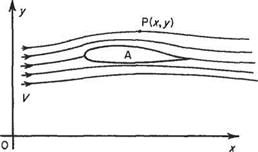
Figure 2. la shows a section of a stationary wing with air flowing past. The velocity of the air a long way from the wing is constant at V, as shown. The flow parameters are measured at some point fixed relative to the wing, e. g. at P(x, y). The flow perturbations produced at P by the body will be the same at all times, i. e. the flow is steady relative to a set of axes fixed in the body.
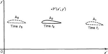
Figure 2.1b represents the same wing moving at the same speed V through air which, a long way from the body, is at rest. The flow parameters are measured at a point P’C*’, /) fixed relative to the stationary air. The wing thus moves past P7. At times t, when the wing is at A, P’ is a fairly large distance ahead of the wing, and the perturbations at P’ are small. Later, at time t2, the wing is at Аг, directly beneath P7, and the perturbations are much larger. Later still, at time Гз, Ґ is far behind the wing, which is now at Аз, and the perturbations are again small. Thus, the perturbation at P’ has started from a small value, increased to a maximum, and finally decreased back to a small value. The perturbation at the fixed point P’ is, therefore, not constant with respect to time, and so the flow, referred to axes fixed in the fluid, is not steady. Thus, changing the axes of reference from a set fixed relative to the air flow, to a different set fixed relative to the body, changes the flow from unsteady to steady. This produces the
|

Fig. 2.1a Air moves at speed V past axes fixed relative to aerofoil
|
|

Fig. 2.1b Aerofoil moves at speed V through air initially at rest. Axes Ox1 0/ fixed relative to undisturbed air at rest
|
mathematical simplification mentioned earlier by eliminating time from the equations. Since the flow relative to the air flow can, by a change of axes, be made steady, it is sometimes known as ‘quasi-steady’.
Consider an aeroplane in steady flight. To an observer on the ground the aeroplane is flying into air substantially at rest, assuming no wind, and any movement of the air is caused directly by the motion of the aeroplane through it. The pilot of the aeroplane, on the other hand, could consider that he is stationary, and that a stream of air is flowing past him and that the aeroplane modifies the motion of the air. In fact both
viewpoints are mathematically and physically correct. Both observers may use the same equations to study the mutual effects of the air and the aeroplane and they will both arrive at the same answers for, say, the forces exerted by the air on the aeroplane. However, the pilot will find that certain terms in the equations become, from his viewpoint, zero. He will, therefore, find that his equations are easier to solve than will the ground-based observer. Because of this it is convenient to regard most problems in aerodynamics as cases of air flowing past a body at rest, with consequent simplification of the mathematics.
Types of flow
The flow round a body may be steady or unsteady. A steady flow is one in which the flow parameters, e. g. speed, direction, pressure, may vary from point to point in the flow but at any point are constant with respect to time, i. e. measurements of the flow parameters at a given point in the flow at various times remain the same. In an unsteady flow the flow parameters at any point vary with time.
Preamble
This chapter is the first of two which set out the fundamental fluid dynamics required for the further development of aerodynamics. In it the study of air in motion starts with the physics and mathematics of one-dimensional fluid motion. Many of the physical phenomena evident in all stages of aerodynamics are most readily approached by considering the one-dimensional mode, without prejudice to the wider analysis of two – and three-dimensional motions.
The laws governing the changes in the physical properties of air are first covered and the relevant mathematics introduced. These laws are applied to the accelerating gas as it moves out of the low-speed ( incompressible) regime and into the transonic and supersonic regimes where the abrupt changes in properties are manifest.
2.1 Introduction
The physical laws that govern fluid flow are deceptively simple. Paramount among them is Newton’s second law of motion which states that:
Mass x Acceleration = Applied force
In fluid mechanics we prefer to use the equivalent form of
Rate of change of momentum = Applied force
Apart from the principles of conservation of mass and, where appropriate, conservation of energy, the remaining physical laws required relate solely to determining the forces involved. For a wide range of applications in aerodynamics the only forces involved are the body forces due to the action of gravity* (which, of course, requires the use of Newton’s theory of gravity; but only in a very simple way); pressure forces (these are found by applying Newton’s laws of motion and require no further physical laws or principles); and viscous forces. To determine the viscous forces we
Body forces are commonly neglected in aerodynamics.
need to supplement Newton’s laws of motion with a constitutive law. For pure homogeneous fluids (such as air and water) this constitutive law is provided by the Newtonian fluid model, which as the name suggests also originated with Newton. In simple terms the constitutive law for a Newtonian fluid states that:
Viscous stress oc Rate of strain
At a fundamental level these simple physical laws are, of course, merely theoretical models. The principal theoretical assumption is that the fluid consists of continuous matter – the so-called continuum model. At a deeper level we are, of course, aware that the fluid is not a continuum, but is better considered as consisting of myriads of individual molecules. In most engineering applications even a tiny volume of fluid (measuring, say, 1 pm3) contains a large number of molecules. Equivalently, a typical molecule travels on average a very short distance (known as the mean free path) before colliding with another. In typical aerodynamics applications the m. f.p. is less than 100 nm, which is very much smaller than any relevant scale characterizing quantities of engineering significance. Owing to this disparity between the m. f.p. and relevant length scales, we may expect the equations of fluid motion, based on the continuum model, to be obeyed to great precision by the fluid flows found in almost all engineering applications. This expectation is supported by experience. It also has to be admitted that the continuum model also reflects our everyday experience of the real world where air and water appear to our senses to be continuous substances.
There are exceptional applications in modem engineering where the continuum model breaks down and ceases to be a good approximation. These may involve very small – scale motions, e. g. nanotechnology and Micro-Electro-Mechanical Systems (MEMS) technology,[4] where the relevant scales can be comparable to the m. f.p. Another example is rarefied gas dynamics (e. g. re-entry vehicles) where there are so few molecules present that the m. f.p. becomes comparable to the dimensions of the vehicle.
We first show in Section 2.2 how the principles of conservation of mass, momentum and energy can be applied to one-dimensional flows to give the governing equations of fluid motion. For this rather special case the flow variables, velocity and pressure, only vary at most with one spatial coordinate. Real fluid flows are invariably three-dimensional to a greater or lesser degree. Nevertheless, in order to understand how the conservation principles lead to equations of motion in the form of partial differential equations, it is sufficient to see how this is done for a twodimensional flow. So this is the approach we will take in Sections 2.4-2.8. It is usually straightforward, although significantly more complicated, to extend the principles and methods to three dimensions. However, for the most part, we will be content to carry out any derivations in two dimensions and to merely quote the final result for three-dimensional flows.
| |


 (2.7)
(2.7)


