Category Aerodynamics for Engineering Students

Basic aerodynamics

1.5.1 Aerodynamic force and moment

Air flowing past an aeroplane, or any other body, must be diverted from its original path, and such deflections lead to changes in the speed of the air. Bernoulli’s equation shows that the pressure exerted by the air on the aeroplane is altered from that of the undisturbed stream. Also the viscosity of the air leads to the existence of frictional forces tending to resist its flow. As a result of these processes, the aeroplane experiences a resultant aerodynamic force and moment. It is conventional and convenient to separate this aerodynamic force and moment into three components each, as follows.

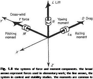
Lift, L[-Z)

This is the component of force acting upwards, perpendicular to the direction of flight or of the undisturbed stream. The word ‘upwards’ is used in the same sense that the pilot’s head is above his feet. Figure 1.7 illustrates the meaning in various attitudes of flight. The arrow V represents the direction of flight, the arrow L represents the lift acting upwards and the arrow W the weight of the aircraft, and shows the downward vertical. Comparison of (a) and (c) shows that this upwards is not Fixed relative to the aircraft, while (a), (b), and (d) show that the meaning is not fixed relative to the earth. As a general rule, if it is remembered that the lift is always

(a) High speed level flight


(b) Climbing flight


Basic aerodynamics

(c) Low speed level flight


Basic aerodynamics

Basic aerodynamicsBasic aerodynamics

Fig. 1.7 The direction of the lift force

a component perpendicular to the flight direction, the exact direction in which the lift acts will be obvious, particularly after reference to Fig. 1.7. This may not apply to certain guided missiles that have no obvious top or bottom, and the exact meaning of ‘up’ must then be defined with care.

Drag, D(-X)

This is the component of force acting in the opposite direction to the line of flight, or in the same direction as the motion of the undisturbed stream. It is the force that resists the motion of the aircraft. There is no ambiguity regarding its direction or sense.

Cross-wind force, Y

This is the component of force mutually perpendicular to the lift and the drag, i. e. in a spanwise direction. It is reckoned positive when acting towards the starboard (right-hand to the pilot) wing-tip.

Pitching moment, M

This is the moment acting in the plane containing the lift and the drag, i. e. in the vertical plane when the aircraft is flying horizontally. It is positive when it tends to increase the incidence, or raise the nose of the aircraft upwards (using this word in the sense discussed earlier).

Rolling moment, LR

This is the moment tending to make the aircraft roll about the flight direction, i. e. tending to depress one wing-tip and to raise the other. It is positive when it tends to depress the starboard wing-tip.

Yawing moment, N

This is the moment that tends to rotate the aircraft about the lift direction, i. e. to swing the nose to one side or the other of the flight direction. It is positive when it swings, or tends to swing, the nose to the right (starboard).

Подпись: Fig. 1.8 The systems of force and moment components. The broad arrows represent forces used in elementary work; the line arrows, the system in control and stability studies. The moments are common to both systems

The relation between these components is shown in Fig. 1.8. In each case the arrow shows the direction of the positive force or moment. All three forces are mutually perpendicular, and each moment acts about the line of one of the forces.

The system of forces and moments described above is conventionally used for performance analysis and other simple problems. For aircraft stability and control studies, however, it is more convenient to use a slightly different system of forces.

Dimensional analysis applied to aerodynamic force

In discussing aerodynamic force it is necessary to know how the dependent variables, aero­dynamic force and moment, vary with the independent variables thought to be relevant.

Assume, then, that the aerodynamic force, or one of its components, is denoted by F and when fully immersed depends on the following quantities: fluid density p, fluid kinematic viscosity v, stream speed V, and fluid bulk elasticity K. The force and moment will also depend on the shape and size of the body, and its orientation to the stream. If, however, attention is confined to geometrically similar bodies, e. g. spheres, or models of a given aeroplane to different scales, the effects of shape as such will be eliminated, and the size of the body can be represented by a single typical dimension; e. g. the sphere diameter, or the wing span of the model aeroplane, denoted by D. Then, following the method above

Подпись: (1.39)F = f(F, D, p, v, K) = EC Vа Dbpcifl Ke

Dimensional analysis applied to aerodynamic force

In dimensional form this becomes

Подпись: (Mass) (Length) (Time) Подпись: 1 = c + e 1 = a + b — 3c + 2d — e -2 = -a-d-2e Подпись: (1.40a) (1.40b) (1.40c)

Equating indices of mass, length and time separately leads to the three equations:

With five unknowns and three equations it is impossible to determine completely all unknowns, and two must be left undetermined. These will be d and e. The variables whose indices are solved here represent the most important characteristic of the body (the diameter), the most important characteristic of the fluid (the density), and the speed. These variables are known as repeated variables because they appear in each dimensionless group formed.

The Eqns (1.40) may then be solved for a, b and c in terms of d and e giving

a — 2 — d — 2e

b = 2-d

c = 1-е

Substituting these in Eqn (1.39) gives

F = V2~d~2eD1~dp[~ei/Ke

Dimensional analysis applied to aerodynamic force(1.41)

The speed of sound is given by Eqns (1.6b, d) namely,

p p

Then

Подпись: К paf /ay ~pV2 = ~руІ = y)p V2 pV2

and Via is the Mach number, M, of the free stream. Therefore Eqn (1.41) may be written as

Подпись: (1.42)F = pV2D2g(^]h{M)

where g(VD/v) and h(M) are undetermined functions of the stated compound vari­ables. Thus it can be concluded that the aerodynamic forces acting on a family of geometrically similar bodies (the similarity including the orientation to the stream), obey the law

This relationship is sometimes known as Rayleigh’s equation.

The term VDjv may also be written, from the definition of v, as pVD/p, as above in the problem relating to the eddy frequency in the flow behind a circular cylinder. It is a very important parameter in fluid flows, and is called the Reynolds number.

Now consider any parameter representing the geometry of the flow round the bodies at any point relative to the bodies. If this parameter is expressed in a suitable non-dimensional form, it can easily be shown by dimensional analysis that this non-dimensional parameter is a function of the Reynolds number and the Mach number only. If, therefore, the values of Re (a common symbol for Reynolds number) and M are the same for a number of flows round geometrically similar bodies, it follows that all the flows are geometrically similar in all respects, differing only in geometric scale and/or speed. This is true even though some of the fluids may be gaseous and the others liquid. Flows that obey these conditions are said to be dynamically similar, and the concept of dynamic similarity is essential in wind-tunnel experiments.

It has been found, for most flows of aeronautical interest, that the effects of compressibility can be disregarded for Mach numbers less than 0.3 to 0.5, and in cases where this limit is not exceeded, Reynolds number may be used as the only criterion of dynamic similarity.

Example 1.1 An aircraft and some scale models of it are tested under various conditions, given below. Which cases are dynamically similar to the aircraft in flight, given as case (А)?

Case (A)

Case (B)

Case (C)

Case (D)

Case (E)

Case (F)

Span (m)

15

3

3

1.5

1.5

3

Relative density

0.533

1

3

1

10

10

Temperature (°С)

-24.6

+ 15

+15

+ 15

+15

+15

Speed (TAS) (ms-1)

100

100

100

75

54

54

Case (A) represents the full-size aircraft at 6000 m. The other cases represent models under test in various types of wind-tunnel. Cases (С), (E) and (F), where the relative density is greater than unity, represent a special type of tunnel, the compressed-air tunnel, which may be operated at static pressures in excess of atmospheric.

Подпись: Case (D) Re = 7.75 x 10⁶ Case (E) Re = 5.55 x 10⁷ Case (F) Re =1.11x10“
Подпись: Case (A) Re = 5.52 x 10⁷ Case (B) Re = 1.84 x 10⁷ Case (C) Re = 5.56 x 10⁷

From the figures given above, the Reynolds number VDpjp, may be calculated for each case. These are found to be

It is seen that the values of Re for cases (C) and (E) are very close to that for the full-size aircraft. Cases (A), (C) and (E) are therefore dynamically similar, and the flow patterns in these three cases will be geometrically similar. In addition, the ratios of the local velocity to the free stream velocity at any point on the three bodies will be the same for these three cases. Hence, from Bernoulli’s equation, the pressure coefficients will similarly be the same in these three cases, and thus the forces on the bodies will be simply and directly related. Cases (B) and (D) have Reynolds numbers considerably less than (A), and are, therefore, said to represent a ‘smaller aerodynamic scale’. The flows around these models, and the forces acting on them, will not be simply or directly related to the force or flow pattern on the full-size aircraft. In case (F) the value of Re is larger than that of any other case, and it has the largest aerodynamic scale of the six.

Example 1.2 An aeroplane approaches to land at a speed of 40m s-1 at sea level. A l/5th scale model is tested under dynamically similar conditions in a Compressed Air Tunnel (CAT) working at 10 atmospheres pressure and 15 °С. It is found that the load on the tailplane is subject to impulsive fluctuations at a frequency of 20 cycles per second, owing to eddies being shed from the wing-fuselage junction. If the natural frequency of flexural vibration of the tailplane is 8.5 cycles per second, could this represent a dangerous condition?

For dynamic similarity, the Reynolds numbers must be equal. Since the temperature of the atmosphere equals that in the tunnel, 15 °С, the value of p. is the same in both model and full-scale cases. Thus, for similarity

Vf£?fPf — Vmdmpm

Dimensional analysis applied to aerodynamic force

In this case, then, since

giving

Vm = 20 ms-1

Dimensional analysis applied to aerodynamic force

Now Eqn (1.38) covers this case of eddy shedding, and is

Dimensional analysis applied to aerodynamic force

For dynamic similarity

Therefore

«r x 1 20 x I

40 = 20

This is very close to the given natural frequency of the tailplane, and there is thus a consider­able danger that the eddies might excite sympathetic vibration of the tailplane, possibly leading to structural failure of that component. Thus the shedding of eddies at this frequency is very dangerous to the aircraft.

Dimensional analysis applied to aerodynamic force

Example 1.3 An aircraft flies at a Mach number of 0.85 at 18300m where the pressure is 7160Nm-2 and the temperature is —56.5 °С. A model of l/10th scale is to be tested in a high­speed wind-tunnel. Calculate the total pressure of the tunnel stream necessary to give dynamic similarity, if the total temperature is 50 °С. It may be assumed that the dynamic viscosity is related to the temperature as follows:

where Tb = 273 °С and po = 1.71×10 5kgm [s 1 (i) Full-scale aircraft

Dimensional analysis applied to aerodynamic force

Dimensional analysis applied to aerodynamic force

M = 0.85, a = 20.05(273 – 56.5)I/2 = 297ms-1
V = 0.85 x 297 = 252 ms-1

p = x 10 5 = 1.44 x 10 5 kgm 1 s 1

Dimensional analysis applied to aerodynamic force

Consider a dimension that, on the aircraft, has a length of 10 m. Then, basing the Reynolds number on this dimension:

Dimensional analysis applied to aerodynamic force

Dimensional analysis applied to aerodynamic force

giving


n = 1.71 x 1.0246 x КГ5 = 1.751 x lO^kgnT1 s_1

287 x 1 x p 1.75 x lO-5

= 20.2 x 10⁶

For dynamic similarity the Reynolds numbers must be equal, i. e.

giving

p = 1.23 kg m 3

Thus the static pressure required in the test section is

p = pRT = 1.23 x 287.3 x 282 = 99 500NnT2 The total pressure p% is given by

(l+±M2) = (1.1445)35 = 1.605

ps = 99 500 x 1.605 = 160000NitT2

If the total pressure available in the tunnel is less than this value, it is not possible to achieve equality of both the Mach and Reynolds numbers. Either the Mach number may be achieved at a lower value of Re or, alternatively, Re may be made equal at a lower Mach number. In such a case it is normally preferable to make the Mach number correct since, provided the Reynolds number in the tunnel is not too low, the effects of compressibility are more important than the effects of aerodynamic scale at Mach numbers of this order. Moreover, techniques are available which can alleviate the errors due to unequal aerodynamic scales.

In particular, the position at which laminar-turbulent transition (see Section 7.9) of the boundary layer occurs at full scale can be fixed on the model by roughening the model surface. This can be done by gluing on a line of carborundum powder.

Dimensional analysis

1.4.1 Fundamental principles

The theory of dimensional homogeneity has additional uses to that described above. By predicting how one variable may depend on a number of others, it may be used to direct the course of an experiment or the analysis of experimental results. For example, when fluid flows past a circular cylinder the axis of which is perpendicular to the stream, eddies are formed behind the cylinder at a frequency that depends on a number of factors, such as the size of the cylinder, the speed of the stream, etc.

In an experiment to investigate the variation of eddy frequency the obvious procedure is to take several sizes of cylinder, place them in streams of various fluids at a number of different speeds and count the frequency of the eddies in each case. No matter how detailed, the results apply directly only to the cases tested, and it is necessary to find some pattern underlying the results. A theoretical guide is helpful in achieving this end, and it is in this direction that dimensional analysis is of use.

In the above problem the frequency of eddies, n, will depend primarily on:

(i) the size of the cylinder, represented by its diameter, d

(ii) the speed of the stream, V

(iii) the density of the fluid, p

(iv) the kinematic viscosity of the fluid, v.

It should be noted that either p от и may be used to represent the viscosity of the fluid.

The factors should also include the geometric shape of the body. Since the problem here is concerned only with long circular cylinders with their axes perpendicular to the stream, this factor will be common to all readings and may be ignored in this analysis. It is also assumed that the speed is low compared to the speed of sound in the fluid, so that compressibility (represented by the modulus of bulk elasticity) may be ignored. Gravitational effects are also excluded.

Then

n = f(d, V, p, v)

and, assuming that this function (…) may be put in the form

n = Y^CdaVbpevf (1.33)

where C is a constant and a, b, e and f are some unknown indices; putting Eqn (1.33) in dimensional form leads to

[Г-1] = [La(LT-1)4(ML-3)e(L2T-1)^] (1.34)

where each factor has been replaced by its dimensions. Now the dimensions of both sides must be the same and therefore the indices of M, L and T on the two sides of the equation may be equated as follows:

Mass (M) 0 = e (1.35a)

Length (L) 0 — a + b — 3e + 2f (1.35b)

Time (T) -1 = – b-f (1.35c)

Here are three equations in four unknowns. One unknown must therefore be left undetermined: /, the index of u, is selected for this role and the equations are solved for a, b and e in terms of f The solution is, therefore,

Подпись: (1.35d) (1.35e) (1.35f) b = -f e = 0

a = – l-f

Substituting these values in Eqn (1.33),

Подпись: or, alternatively, Подпись: (1.37)
Dimensional analysis

Rearranging Eqn (1.36), it becomes

Dimensional analysis(1.38)

where g represents some function which, as it includes the undetermined constant C and index f is unknown from the present analysis.

Although it may not appear so at first sight, Eqn (1.38) is extremely valuable, as it shows that the values of nd/V should depend only on the corresponding value of Vd/u, regardless of the actual values of the original variables. This means that if, for each observation, the values of nd/V and Vdjv are calculated and plotted as a graph, all the results should lie on a single curve, this curve representing the unknown function g. A person wishing to estimate the eddy frequency for some given cylinder, fluid and speed need only calculate the value of Vd/v, read from the curve the corresponding value of nd/V and convert this to eddy frequency n. Thus the results of the series of observations are now in a usable form.

Consider for a moment the two compound variables derived above:

(a) nd/V. The dimensions of this are given by

~ = [T-1 x L x (LT"1)-1] = [L°T°] = [1]

(b) Vd/v. The dimensions of this are given by

~ = [(LT_1) x L x (L2T-1)-1] = [1]

Thus the above analysis has collapsed the five original variables n, d, V, p and v into two compound variables, both of which are non-dimensional. This has two advantages: (i) that the values obtained for these two quantities are independent of the consistent system of units used; and (ii) that the influence of four variables on a fifth term can be shown on a single graph instead of an extensive range of graphs.

It can now be seen why the index/was left unresolved. The variables with indices that were resolved appear in both dimensionless groups, although in the group nd/V the density p is to the power zero. These repeated variables have been combined in turn with each of the other variables to form dimensionless groups.

There are certain problems, e. g. the frequency of vibration of a stretched string, in which all the indices may be determined, leaving only the constant C undetermined. It is, however, usual to have more indices than equations, requiring one index or more to be left undetermined as above.

It must be noted that, while dimensional analysis will show which factors are not relevant to a given problem, the method cannot indicate which relevant factors, if any, have been left out. It is, therefore, advisable to include all factors likely to have any bearing on a given problem, leaving out only those factors which, on a priori considerations, can be shown to have little or no relevance.

Camber

At any distance along the chord from the nose, a point may be marked mid-way between the upper and lower surfaces. The locus of all such points, usually curved, is the median line of the section, usually called the camber line. The maximum height of the camber line above the chord line is denoted by 6 and the quantity 100<5/c% is called the percentage camber of the section. Aerofoil sections have cambers that are usually in the range from zero (a symmetrical section) to 5%, although much larger cambers are used in cascades, e. g. turbine blading.

It is seldom that a camber line can be expressed in simple geometric or algebraic forms, although a few simple curves, such as circular arcs or parabolas, have been used.

Thickness distribution

Having found the median, or camber, line, the distances from this line to the upper and lower surfaces may be measured at any value of. v. These are, by the definition of the camber line, equal. These distances may be measured at all points along the chord and then plotted against x from a straight line. The result is a symmetrical shape, called the thickness distribution or symmetrical fairing.

An important parameter of the thickness distribution is the maximum thickness, or depth, t. This, when expressed as a fraction of the chord, is called the thickness/ chord ratio. It is commonly expressed as a percentage 100//c‘%. Current values in use range from 13% to 18% for subsonic aircraft down to 3% or so for supersonic aircraft.

The position along the chord at which this maximum thickness occurs is another important parameter of the thickness distribution. Values usually lie between 30% and 60% of the chord from the leading edge. Some older sections had the maximum thickness at about 25% chord, whereas some more extreme sections have the max­imum thickness more than 60% of the chord behind the leading edge.

It will be realized that any aerofoil section may be regarded as a thickness distribution plotted round a camber line. American and British conventions differ in the exact method of derivation of an aerofoil section from a given camber line and thickness distribution. In the British convention, the camber line is plotted, and the thickness ordinates are then plotted from this, perpendicular to the chord line. Thus the thickness distribution is, in effect, sheared until its median line, initially straight, has been distorted to coincide with the given camber line. The American convention is that the thickness ordinates are plotted perpendicular to the curved camber line. The thickness distribution is, therefore, regarded as being bent until its median line coincides with the given camber line.

Since the camber-line curvature is generally very small the difference in aerofoil section shape given by these two conventions is very small.

Aerofoil geometry

Подпись: Fig. 1.5 Illustrating the dihedral angle

If a horizontal wing is cut by a vertical plane parallel to the centre-line, such as X-X in Fig. 1.4, the shape of the resulting section is usually of a type shown in Fig. 1.6c.

Aerofoil geometry
This is an aerofoil section. For subsonic use, the aerofoil section has a rounded leading edge. The depth increases smoothly to a maximum that usually occurs between £ and way along the profile, and thereafter tapers off towards the rear of the section.

If the leading edge is rounded it has a definite radius of curvature. It is therefore possible to draw a circle of this radius that coincides with a very short arc of the section where the curvature is greatest. The trailing edge may be sharp or it, too, may have a radius of curvature, although this is normally much smaller than for the leading edge. Thus a small circle may be drawn to coincide with the arc of maximum curvature of the trailing edge, and a line may be drawn passing through the centres of maximum curvature of the leading and trailing edges. This line, when produced to intersect the section at each end, is called the chord line. The length of the chord line is the aerofoil chord, denoted by c.

The point where the chord line intersects the front (or nose) of the section is used as the origin of a pair of axes, the x-axis being the chord line and the j-axis being perpendicular to the chord line, positive in the upward direction. The shape of the section is then usually given as a table of values of x and the corresponding values of y. These section ordinates are usually expressed as percentages of the chord, (100x/c)% and (100yjc)%.

Aeronautical definitions

1.3.1 Wing geometry

The planform of a wing is the shape of the wing seen on a plan view of the aircraft. Figure 1.4 illustrates this and includes the names of symbols of the various para­meters of the planform geometry. Note that the root ends of the leading and trailing edges have been connected across the fuselage by straight lines. An alternative to this convention is that the leading and trailing edges, if straight, are produced to the aircraft centre-line.

x

CL

Aeronautical definitions

s


Aeronautical definitions

b-2.s

Fig. 1.4 Wing planform geometry


Wing span

The wing span is the dimension b, the distance between the extreme wingtips. The distance, s, from each tip to the centre-line, is the wing semi-span.

Chords

The two lengths cT and c0 are the tip and root chords respectively; with the alter­native convention, the root chord is the distance between the intersections with the fuselage centre-line of the leading and trailing edges produced. The ratio ct/c0 is the taper ratio Л. Sometimes the reciprocal of this, namely c0/ct, is taken as the taper ratio. For most wings cj/co < 1.

Wing area

The plan-area of the wing including the continuation within the fuselage is the gross wing area, SG – The unqualified term wing area S is usually intended to mean this gross wing area. The plan-area of the exposed wing, i. e. excluding the continuation within the fuselage, is the net wing area, SN.

Mean chords

Aeronautical definitions

A useful parameter, the standard mean chord or the geometric mean chord, is denoted by c, defined by c = Sq/Ь or Ss/b. It should be stated whether SG or SN is used. This definition may also be written as

where у is distance measured from the centre-line towards the starboard (right-hand to the pilot) tip. This standard mean chord is often abbreviated to SMC.

Aeronautical definitions

Another mean chord is the aerodynamic mean chord (AMC), denoted by ca or 5, and is defined by

Aspect ratio

The aspect ratio is a measure of the narrowness of the wing planform. It is denoted by A, or sometimes by (АЛ), and is given by

Подпись: SMC cд _ span _ b

If both top and bottom of this expression are multiplied by the wing span, becomes:

Подпись: b, itA _ b2 _. (span)2 be area

a form which is often more convenient.

Sweep-back

The sweep-back angle of a wing is the angle between a line drawn along the span at a constant fraction of the chord from the leading edge, and a line perpendicular to the centre-line. It is usually denoted by either Л or ф. Sweep-back is commonly measured on the leading edge (Ale or <^>le)> on the quarter-chord line, i. e. the line of the chord behind the leading edge (Л1/4 or фщ), or on the trailing edge (Ate or Фте)-

Dihedral angle

If an aeroplane is looked at from directly ahead, it is seen that the wings are not, in general, in a single plane (in the geometric sense), but are instead inclined to each other at a small angle. Imagine lines drawn on the wings along the locus of the intersections between the chord lines and the section noses, as in Fig. 1.5. Then the angle 2Г is the dihedral angle of the wings. If the wings are inclined upwards, they are said to have dihedral, if inclined downwards they have anhedral.

Incidence, twist, wash-out and wash-in

When an aeroplane is in flight the chord lines of the various wing sections are not normally parallel to the direction of flight. The angle between the chord line of a given aerofoil section and the direction of flight or of the undisturbed stream is called the geometric angle of incidence, a.

Carrying this concept of incidence to the twist of a wing, it may be said that, if the geometric angles of incidence of all sections are not the same, the wing is twisted. If the incidence increases towards the tip, the wing has wash-in, whereas if the incidence decreases towards the tip the wing has wash-out.

Thermodynamic properties

Heat, like work, is a form of energy transfer. Consequently, it has the same dimen­sions as energy, i. e. ML2T-2, and is measured in units of Joules (J).

Specific heat

The specific heat of a material is the amount of heat necessary to raise the tempera­ture of unit mass of the material by one degree. Thus it has the dimensions L2T-20_1 and is measured in units of Jkg-1 °С-1 or Jkg_I K-1.

With a gas there are two distinct ways in which the heating operation may be performed: at constant volume and at constant pressure, and in turn these define important thermodynamic properties.

Specific heat at constant volume If unit mass of the gas is enclosed in a cylinder sealed by a piston, and the piston is locked in position, the volume of the gas cannot change, and any heat added is used solely to raise the temperature of the gas, i. e. the head added goes to increase the internal energy of the gas. It is assumed that the cylinder and piston do not receive any of the heat. The specific heat of the gas under these conditions is the specific heat at constant volume, cv. For dry air at normal aerodynamic temperatures, су = 718 J kg-1 K-1.

Internal energy (E) is a measure of the kinetic energy of the molecules comprising the gas. Thus

internal energy per unit mass E = cyT

Thermodynamic properties Подпись: (1.7)

or, more generally,

Specific heat at constant pressure Assume that the piston referred to above is now freed and acted on by a constant force. The pressure of the gas is that necessary to resist the force and is therefore constant. The application of heat to the gas causes its temperature to rise, which leads to an increase in the volume of the gas, in order to maintain the constant pressure. Thus the gas does mechanical work against the force. It is therefore necessary to supply the heat required to increase the temperature of the gas (as in the case at constant volume) and in addition the amount of heat equivalent to the mechanical work done against the force. This total amount of heat is called the specific heat at constant pressure, cp, and is defined as that amount of heat required to raise the temperature of unit mass of the gas by one degree, the pressure of the gas being kept constant while heating. Therefore, cp is always greater than cv. For dry air at normal aerodynamic temperatures, cp = 1005 J kg-1 K-1.

Now the sum of the internal energy and pressure energy is known as the enthalpy (h per unit mass) (see below). Thus

h = cpT

Thermodynamic properties

Entropy

Entropy is a function of state that follows from, and indicates the working of, the second law of thermodynamics, that is concerned with the direction of any process involving heat and energy. Entropy is a function the positive increase of which during an adiabatic process indicates the consequences of the second law, i. e. a reduction in entropy under these circumstances contravenes the second law. Zero entropy change indicates an ideal or completely reversible process.

By definition, specific entropy (5)* (Joules per kilogram per Kelvin) is given by the integral

It should be remembered that this result is obtained from the equation of state for a perfect gas and the equation of conservation of energy of the flow of a non-heat­conducting inviscid fluid. Such a flow behaves isentropically and, notwithstanding the apparently restrictive nature of the assumptions made above, it can be used as a model for a great many aerodynamic applications.


(1.25)


for any reversible process, the integration extending from some datum condition; but, as seen above, it is the change in entropy that is important, i. e.


T


(1.26)


In this and the previous equation dQ is a heat transfer to a unit mass of gas from an external source. This addition will go to changing the internal energy and will do work. Thus, for a reversible process,


dQ = d£ + pd 1^- dg = cvdT pd{/p)

j j I j


(1.27)


but p/T = Rp, therefore


(128)

Integrating Eqn (1.28) from datum conditions to conditions given by suffix 1,

Si = си1п-5- + Д1п^

Ти pi


Likewise,


S2 = cvu^+ Ru^ Ти Pi


* Note that in this passage the unconventional symbol S is used for specific entropy to avoid confusion with the length symbols.


Thermodynamic properties Thermodynamic properties

and the entropy change from conditions 1 to 2 is given by

Thermodynamic properties(1.32)

These latter expressions find use in particular problems.

Speed of sound and bulk elasticity

Speed of sound and bulk elasticity Подпись: 1 dp VdV Подпись: (1.6a)

The bulk elasticity is a measure of how much a fluid (or solid) will be compressed by the application of external pressure. If a certain small volume, V, of fluid is subjected to a rise in pressure, 6p, this reduces the volume by an amount —6V, i. e. it produces a volumetric strain of —6V/V. Accordingly, the bulk elasticity is defined as

The volumetric strain is the ratio of two volumes and evidently dimensionless, so the dimensions of К are the same as those for pressure, namely ML_1T~2. The SI units are Nm“2 (or Pa).

The propagation of sound waves involves alternating compression and expansion of the medium. Accordingly, the bulk elasticity is closely related to the speed of sound, a, as follows:

Speed of sound and bulk elasticity(1.6b)

Speed of sound and bulk elasticity Подпись: dV -p~r Подпись: dp =

Let the mass of the small volume of fluid be M, then by definition the density, p = М/ V. By differentiating this definition keeping M constant, we obtain

Therefore, combining this with Eqns (1.6a, b), it can be seen that

Подпись: a —(1.6c)

The propagation of sound in a perfect gas is regarded as an isentropic process. Accordingly, (see the passage below on Entropy) the pressure and density are related by Eqn (1.24), so that for a perfect gas

Speed of sound and bulk elasticity(1.6d)

where 7 is the ratio of the specific heats. Equation (1.6d) is the formula usually used to determine the speed of sound in gases for applications in aerodynamics.

Viscosity

Viscosity is regarded as the tendency of a fluid to resist sliding between layers or, more rigorously, a rate of change of shear strain. There is very little resistance to the movement of a knife-blade edge-on through air, but to produce the same motion through thick oil needs much more effort. This is because the viscosity of oil is high compared with that of air.

Dynamic viscosity

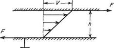
The dynamic (more properly called the coefficient of dynamic, or absolute, viscosity) viscosity is a direct measure of the viscosity of a fluid. Consider two parallel flat plates placed a distance h apart, the space between them being filled with fluid. One plate is held fixed and the other is moved in its own plane at a speed V (see Fig. 1.3). The fluid immediately adjacent to each plate will move with that plate, i. e. there is no slip. Thus the fluid in contact with the lower plate will be at rest, while that in contact with the upper plate will be moving with speed V. Between the plates the speed of the fluid will vary linearly as shown in Fig. 1.3, in the absence of other influences. As a direct result of viscosity a force F has to be applied to each plate to maintain the motion, the fluid tending to retard the moving plate and to drag the fixed plate to the right. If the area of fluid in contact with each plate is A, the shear stress is F/A. The rate of shear strain caused by the upper plate sliding over the lower is Vfh.

These quantities are connected by Newton’s equation, which serves to define the dynamic viscosity ц. This equation is

Viscosity

Hence

[ML-‘T-2] – MfLT-‘L-1] = МГГ-1]

Thus

M = [ML-‘T-1]

and the units of ц are therefore kgm-1 s-1; in the SI system the name Poiseuille (PI) has been given to this combination of fundamental units. At 0°C (273 K) the dynamic viscosity for dry air is 1.714 x 1 O’5kgm-1 s-1.

The relationship of Eqn (1.5) with ц constant does not apply for all fluids. For an important class of fluids, which includes blood, some oils and some paints, ц is not constant but is a function of Vfh, i. e. the rate at which the fluid is shearing.

Kinematic viscosity

The kinematic viscosity (or, more properly, coefficient of kinematic viscosity) is a convenient form in which the viscosity of a fluid may be expressed. It is formed

Viscosity

Fig. 1.3
dynamic viscosity p according to the

Подпись: by combining the density p and the equation-t

P

and has the dimensions L2T-1 and the units m2 s_1.

It may be regarded as a measure of the relative magnitudes of viscosity and inertia of the fluid and has the practical advantage, in calculations, of replacing two values representing p and p by a single value.

Temperature

In any form of matter the molecules are in motion relative to each other. In gases the motion is random movement of appreciable amplitude ranging from about 76 x 10-9 metres under normal conditions to some tens of millimetres at very low pressures. The distance of free movement of a molecule of gas is the distance it can travel before colliding with another molecule or the walls of the container. The mean value of this distance for all the molecules in a gas is called the length of mean molecular free path.

By virtue of this motion the molecules possess kinetic energy, and this energy is sensed as the temperature of the solid, liquid or gas. In the case of a gas in motion it is called the static temperature or more usually just the temperature. Temperature has the dimension [0] and the units К or °С (Section 1.1). In practically all calculations in aerodynamics, temperature is measured in K, i. e. from absolute zero.

1.2.2 Density

The density of a material is a measure of the amount of the material contained in a given volume. In a fluid the density may vary from point to point. Consider the fluid contained within a small spherical region of volume 6V centred at some point in the fluid, and let the mass of fluid within this spherical region be dm. Then the density of the fluid at the point on which the sphere is centred is defined by

_ . ..6m.. t.

Density p= km — (1.4)

tfv—►О О V

The dimensions of density are thus ML-3, and it is measured in units of kilogram per cubic metre (kgm-3). At standard temperature and pressure (288 K, 101 325 Nm-2) the density of dry air is 1.2256 kgm-3.

Difficulties arise in applying the above definition rigorously to a real fluid composed of discrete molecules, since the sphere, when taken to the limit, either will or will not contain part of a molecule. If it does contain a molecule the value obtained for the density will be fictitiously high. If it does not contain a molecule the resultant value for the density will be zero. This difficulty can be avoided in two ways over the range of temperatures and pressures normally encountered in aerodynamics:

(i) The molecular nature of a gas may for many purposes be ignored, and the assumption made that the fluid is a continuum, i. e. does not consist of discrete particles.

(ii) The decrease in size of the imaginary sphere may be supposed to be carried to a limiting minimum size. This limiting size is such that, although the sphere is small compared with the dimensions of any physical body, e. g. an aeroplane, placed in the fluid, it is large compared with the fluid molecules and, therefore, contains a reasonable number of whole molecules.