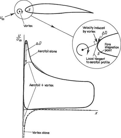
Since flow separation is due to the complete loss of kinetic energy in the boundary layer immediately adjacent to the wall, another method of preventing it is to re-energize the ‘tired’ air by blowing a thin, high-speed jet into it. This method is often used with trailing-edge flaps (Fig. 8.25). To obtain reasonable results with this
Coanda effect over this curved surface


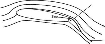 method, great care must be taken with the design of the blowing duct. It is essential that good mixing takes place between the blown air and the boundary layer.
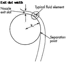
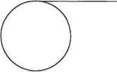
Most applications of tangential blowing for flow control exploit the so-called Coanda effect. This name is used for the tendency of a fluid jet issuing tangentially on to a curved or angled solid surface to adhere to it, as illustrated in Fig. 8.26. The name derives from the Franco-Romanian engineer, Henri Coanda, who filed a French patent in 1932 for a propulsive device exploiting the phenomenon. The explanation for the phenomenon can be understood by considering the radial equilibrium of the fluid element depicted in Fig. 8.26a. This can be expressed in simple terms as follows: where p is the pressure within the jet boundary layer (strictly, the wall jet) issuing from the nozzle exit slot, r is the radial distance from the centre of curvature of the surface, p is the fluid density, and V is the local flow speed. It is easy to see that the pressure field thereby created forces the flow issuing from the nozzle to adhere to the surface. But this does not explain why the equally valid flow solution shown in Fig. 8.26b is only found in practice when the Coanda effect breaks down. Presumably the slightly enhanced viscous drag, experienced by the jet on its surface side as it emerges from the nozzle, tends to deflect it towards the surface. Thereafter, the pressure field set up by the requirements of radial equilibrium will tend to force the jet towards the surface. Another viscous effect, namely entrainment of the fluid between the jet and the surface, may also help pull the jet towards the surface.
The practical limits on the use of the Coanda effect can also be understood to a certain extent by considering the radial equilibrium of the fluid element depicted in Fig. 8.26a. Initially we will assume that the flow around the curved surface is inviscid so that it obeys Bernoulli’s equation
 (8.2)
(8.2)
where po is the stagnation pressure of the flow issuing from the nozzle. Equation (8.2) may be substituted into Eqn (8.1) which is then rearranged to give
 (8.3)
(8.3)
(a) Normal coanda flow (b) Jet break-away
Fig. 8.26 The Coanda effect – the flow of a jet around a circular cylinder Source: Based on Fig. 1 of P. W. Carpenter and P. N. Green (1997) The aeroacoustics and aerodynamics of high-speed Coanda devices’, J. Sound & Vibration, 208(5), 777-801
where Vw is the (inviscid) flow speed along the wall and Rc is the radius of curvature of the surface. When the ratio of the exit-slot width, b, to the radius of curvature is small, r ~ Rc and V ~ Vw. It then follows from Eqn (8.1) that near the exit slot the pressure at the wall is given by
where Рос is the ambient pressure outside the Coanda flow.
It can be seen from Eqn (8.4) that the larger pV2b/Rc is, the more the wall pressure falls below poo. In the actual viscous flow the average flow speed tends to fall with distance around the surface. As a consequence, the wall pressure rises with distance around the surface, thereby creating an adverse pressure gradient and eventual separation. This effect is intensified for large values of pV2b/Rc, so the nozzle exit – slot height, b, must be kept as small as possible. For small values of b/Rc the Coanda effect may still break down if the exit flow speed is high enough. But the simple analysis leading to Eqn (8.4) ignores compressible-flow effects. In fact, the blown air normally reaches supersonic speeds before the Coanda effect breaks down. At sufficiently high supersonic exit speeds shock-wave/boundary-layer interaction will provoke flow separation and cause the breakdown of the Coanda effect.* This places practical limits on the strength of blowing that can be employed.
The Coanda principle may be used to delay separation over the upper surface of a trailing-edge flap. The blowing is usually powered by air ducted from the engines. By careful positioning of the flap surface relative to the blown air jet and the main wing surface, advantage can be taken of the Coanda effect to make the blown jet adhere to the upper surface of the flap even when it is deflected downwards by as much as 60° (Fig. 8.25). In this way the circulation around the wing can be greatly enhanced.
|
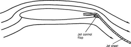
Fig. 8.27 A jet flap with a vestigial control flap
|
A more extreme version of the principle is depicted in Fig. 8.27 where only a vestigial flap is used. This arrangement is occasionally found at the trailing edge of a conventional blown flap. The term jet flap has sometimes been applied to this device, but the term is used rather imprecisely; it has even been applied to blown-flap systems in general. Here we will reserve the term for the case where the air is blown so strongly as to be supersonic. Such an arrangement is found on fighter aircraft with small wings, such as the Lockheed F-104 Starfighter, the Mig-21 PFM, and the McDonnell Douglas F-4 Phantom. This was done in order to increase lift at low speeds, thereby reducing the landing speed. The air is bled from the engine compressor and blown over the trailing-edge flaps. According to McCormick,* prior to 1951 it was thought that, if supersonic blown air were to be used, it would not only fail to adhere to the flap surface, but also lead to unacceptable losses due to the formation of shock waves. This view was dispelled by an undergraduate student, John Attinello, in his honours thesis at Lafayette College in the United States. Subsequently, his concept was subjected to more rigorous and sophisticated experimental studies before being flight tested and ultimately used on many aircraft, including the examples mentioned above.
|
Table 8.1 Aerodynamic performance of some high-lift systems
|
System
|
Cc™,
|
|
Internally blown flap
|
9
|
|
Upper surface blowing
|
8
|
|
Externally blown flap
|
7
|
|
Vectored thrust
|
3
|
|
Boeing 767 with slat + triple flap
|
2.8
|
|
Boeing 727 with slat + single flap
|
2.45
|
Source: Based on Tables 2 and 3 of A. Filippone 1999-2001 Aerodynamics Database – Lift Coefficients (http://aerodyn. org/ HighLift/tables. html).
|
B. W. McCormick (1979) Aerodynamics, Aeronautics and Flight Mechanics, Wiley.
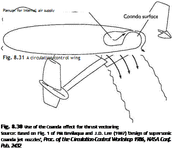
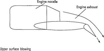
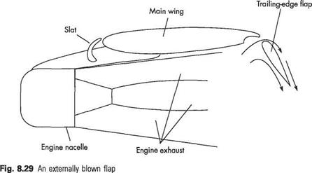
Internally blown flaps give the best performance of any high-lift system, see Table 8.1, but upper surface blowing (Fig. 8.28) is also very effective. This arrangement is used on various versions of the Antonov An 72/74 transport aircraft. A slightly less efficient system is the externally blown flap (Fig. 8.29). A version of this is used on the Boeing C-17 Globemaster heavy transport aircraft. The engine exhaust flow is directed below and through slotted flaps to produce an additional lifting force. This allows the aircraft to make a steep, low-speed, final approach with a low landing speed for routine short-field landings. Many STOL (Short Take-Off and Landing) aircraft and fighter aircraft make use of thrust vectoring that also exploits the Coanda effect. One possible arrangement is depicted in Fig. 8.30.
Blown flaps and some other high-lift systems actually generate substantial additional circulation and do not just generate the required high lift owing to an increased angle of attack. For this reason in some applications the term circulation-control wings is often used. It is not necessary to install a flap on a circulation-control wing. For example, see the system depicted in Fig. 8.31. Rotors have been fitted with both suction-type circulation control (see Fig. 8.23) and the more common blown and jet flaps, and have been tested on a variety of helicopter prototypes.[66] But, as yet, circulation-control rotors
have not been used on any production aircraft. A recent research development, mainly in the last 10 years, is the use of periodic blowing for separation control.[67] Significant lift enhancement can be achieved efficiently with the use of very low flow rates. Almost all the experimental studies are at fairly low Reynolds number, but Seifert and Pack* have carried out wind-tunnel tests at Reynolds numbers typical of flight conditions.
Tangential blowing can only be applied to the prevention of separation, unlike suction that can be employed for this purpose or for laminar-flow control. The flow created by blowing tends to be very vulnerable to laminar-turbulent transition, so tangential blowing almost inevitably triggers transition.


 method, great care must be taken with the design of the blowing duct. It is essential that good mixing takes place between the blown air and the boundary layer.


![Movable flaps: artificial bird feathers[63] Movable flaps: artificial bird feathers[63]](/img/3130/image1706.jpg)
![Movable flaps: artificial bird feathers[63] Movable flaps: artificial bird feathers[63]](/img/3130/image1707.jpg)
