Note that
 dв _ 26{L)
where в(Ь) is the value of the momentum thickness at x = L. Thus using Eqn (7.70) in Eqn (7.71) gives
CF – 1.293/Jte1/2 and
CDv = 2.586/Jte1/2 (7.72)
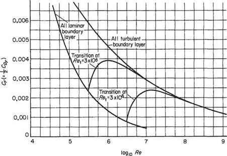
These expressions are shown plotted in Fig. 7.25 (lower curve).
Example 7.3 A flat plate of 0.6 m chord at zero incidence in a uniform airstream of 45 m s-1. Estimate (i) the displacement thickness at the trailing edge, and (ii) the overall drag coefficient of the plate.
At the trailing edge, x = 0.6 m and
|
5* = 1-^ * в _ 0.765 x 10 3 m = 0.8 mm л/Шх 103
Re has the same value as Rex at the trailing edge. So Eqn (7.72) gives
2.54
|
Therefore, using Eqn (7.69),
7.7.1 Turbulent velocity profile
A commonly employed, turbulent-boundary-layer profile is the seventh-root profile, which was proposed by Prandtl on the basis of friction-loss experiments with turbulent flow in circular pipes correlated by Blasius. The latter investigated experimental results on the resistance to flow and proposed the following empirical relationships between the local skin friction coefficient at the walls, Cf(=rw/|p£/ ) and the Reynolds number of the flow Re (based on the average flow velocity U in the pipe and the diameter D). Blasius proposed the relationship
This expression gives reasonably good agreement with experiment for values of Re up to about 2.5 x 10⁵.
Assuming that the velocity profile in the pipe may be written in the form
where и is the velocity at distance у from the wall and a = pipe radius Djl, it remains to determine the value of n. From Eqn (7.74), writing Um = CU, where C is a constant to be determined: i. e.
(7.75)
Substituting for Cf in the expression above for surface friction stress at the wall,
 "І-”2 °-0791у1/4 lpU2 = 0.03955pU7/4(^y/4 (7.76)
From Eqn (7.75)
-7/4_«7/4 faln/A ~ СУ4
|
Tw = РиУ4*алТ,(їт г1/4їЛ 1/4
|
so that Eqn (7.76) becomes
i. e.
It may now be argued that very close to the wall, in the viscous sublayer (и Ф 0), the velocity и will not depend on the overall size of the pipe, i. e. that и Ф f(a). If this is so, then it immediately follows that rw, which is p(du/dy)v,, cannot depend on the pipe diameter and therefore the term aKVn/4)—(i/4)] jn pqn (7.77) must be unity in order not to affect the expression for rw. For this to be so, 7л/4 -1/4 = 0 which immediately gives n = j. Substituting this back into Eqn (7.74) gives u/Um = (yja)1/7. This expression thus relates the velocity и at distance у from the surface to the centre-line velocity Um at distance a from the surface. Assuming that this will hold for very large pipes, it may be argued that the flow at a section along a flat, two-dimensional plate is similar to that along a small peripheral length of pipe, so that replacing a by 6 will give the profile for the free boundary layer on the flat plate. Thus
This is Prandtl’s seventh-root law and is found to give surprisingly good overall agreement with practice for moderate Reynolds numbers (Rex < 107). It does, however, break down at the wall where the profile is tangential to the surface and gives an infinite value of (дй/дуХr In order to find the wall shear stress, Eqn (7.77) must be used. The constant Cmay be evaluated by equating expressions for the total volume flow through the pipe, i. e. (using Eqns (7.75) and (7.78)),
Га – fa /v 1/7 49 _
naiU = 2n urdr = 2nUC (-) (a — y)dy = — irUCa1
Jo Jo ‘a’ 60
giving C = — = 1.224. Substituting for C and n in Eqn (7.77) then gives
 rw = 0.0234/эи7/4
that, on substituting for и from Eqn (7.78), gives
Finally, since
for a free boundary layer:
Using Eqns (7.78) and (7.80) in the momentum integral equation enables the growth of the turbulent boundary layer on a flat plate to be investigated.
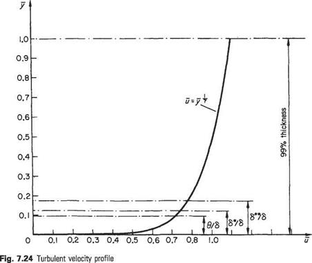
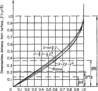
The seventh-root profile with the above thickness quantities indicated is plotted in Fig. 7.24.
Example 7.4 A wind-tunnel working section is to be designed to work with no streamwise pressure gradient when running empty at an airspeed of 60ms-1. The working section is 3.6 m long and has a rectangular cross-section which is 1.2 m wide by 0.9 m high. An approximate allowance for boundary-layer growth is to be made by allowing the side walls of the working section to diverge shghtly. It is to be assumed that, at the upstream end of the working section, the turbulent boundary layer is equivalent to one that has grown from zero thickness over a length of 2.5 m; the wall divergence is to be determined on the assumption that the net area of flow is correct at the entry and exit sections of the working section. What must be the width between the walls at the exit section if the width at the entry section is exactly 1.2 m?
|
6* = 0’0479* (Eqn (7.82))
|
For the seventh-root profile:
At entry, x = 2.5 m. Therefore

 Uxx 60 x 2.5 v = 14.6 x 10⁻⁶ RelJ5 = 25.2
„ 0.0479 x 2.5
=—— ^r-r—– = 0.00475m
25.2

At exit, x = 6.1 m. Therefore

 60 x 6.1
14.6 x 10⁻⁶ RelJs = 30.2
^ = 00479,x 6л = ooo968m
Thus <5* increases by (0.00968 — 0.00475) = 0.00493 m. This increase in displacement thickness occurs on all four walls, i. e. total displacement area at exit (relative to entry) = 0.00493 x 2(1.2 + 0.9) = 0.0207m2.
The allowance is to be made on the two side walls only so that the displacement area on side walls = 2 x 0.9 x Д” = 1.8Д*т2, where Д* is the exit displacement per wall. Therefore
Д*=^ = 0.0115т 1.0
This is the displacement for each wall, so that the total width between side walls at the exit section = 1.2 + 2 x 0.0115 = 1.223 m.







 dx P e dx