Category Aerodynamics for Engineering Students

Flow past cylinders and spheres

Some of the properties of boundary layers discussed above help in the explanation of the behaviour, under certain conditions, of a cylinder or sphere immersed in a uniform free stream. So far discussion has been restricted to the flow over bodies of reasonably streamline form, behind which a relatively thin wake is formed. In such cases, the drag forces are largely due to surface friction, i. e. to shear stresses at the base of the boundary layer. When dealing with non-streamlined or bluff bodies, it is found that, because of the adverse effect of a positive pressure gradient on the boundary layer, the flow usually separates somewhere near points at the maximum cross-section, with the formation of a broad wake. As a result, the skin-friction drag is only small, and the major part of the total drag now consists of form drag due to the large area at the rear of the body acted upon by a reduced pressure in the wake region. Experimental observation of the flow past a sphere or cylinder indicates that the drag of the body is markedly influenced by the cross­sectional area of the wake, a broad wake being accompanied by a relatively high drag and vice versa.

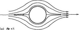
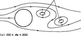
The way in which the flow pattern around a bluff body can change dramatically as the Reynolds number is varied may be considered with reference to the flow past a circular cylinder. For the most part the flow past a sphere also behaves in a similar way. At very low Reynolds number,* i. e. less than unity, the flow behaves as if it were purely viscous with negligible inertia. Such flow is known as creeping or Stokes flow. For such flows there are no boundary layers and the effects of viscosity extend an infinite distance from the body. The streamlines are completely symmetrical fore and aft, as depicted in Fig. 7.15a. In appearance the streamline pattern is superficially similar to that for potential flow. For creeping flow, however, the influence of the cylinder on the streamlines extend to much greater distances than for potential flow. Skin-friction drag is the only force generated by the fluid flow on the cylinder. Consequently, the body with the lowest drag for a fixed volume is the sphere.

Подпись: 400

Wide turbulent wake

Flow past cylinders and spheres


Flow separation

Flow past cylinders and spheres


Alternate vortex formation in a brood wake

Flow past cylinders and spheres

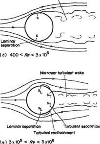
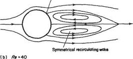
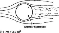
Fig. 7.15 (Note that the Reynolds number limits quoted are only approximate, as they depend


Flow past cylinders and spheres

appreciably on the free-stream turbulence level)


Flow past cylinders and spheres

Perhaps, it is for this reason that microscopic swimmers such as protozoa, bacteria and spermatazoa tend to be near-spherical. In the range 1 < Re < 5, the streamline pattern remains fairly similar to that of Fig. 7.15a, except that as Re is increased within this range a more and more pronounced asymmetry develops between the fore and aft directions. Nevertheless, the flow remains attached.

When Re exceeds a value of about 5, a much more profound change in the flow pattern occurs. The flow separates from the cylinder surface to form a closed wake of recirculating flow – see Fig. 7.15b. The wake grows progressively in length as Re is increased from 5 up to about 41. The flow pattern is symmetrical about the hori­zontal axis and is steady, i. e. it does not change with time. At these comparatively low Reynolds numbers the effects of viscosity still extend a considerable distance from the surface, so it is not valid to use the concept of the boundary layer, nevertheless the explanation for flow separation occurring is substantially the same as that given in Section 7.4.

When Re exceeds a value of about 41 another profound change occurs; steady flow becomes impossible. In some respects what happens is similar to the early stages of laminar-turbulent transition (see Section 7.9), in that the steady recirculating wake flow, seen in Fig. 7.15b, becomes unstable to small disturbances. In this case, though, the small disturbances develop as vortices rather than waves. Also in this case, the small disturbances do not develop into turbulent flow, but rather a steady laminar wake develops into an unsteady, but stable, laminar wake. The vortices are generated

Flow past cylinders and spheres

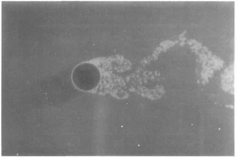
Fig. 7.16 The wake of a circular cylinder at Reo ~ 5000: Vortices are formed when flow passes over circular cylinders for a wide range of Reynolds numbers – see Fig. 7.15 on page 400. The flow is from left to right. The Reynolds number is sufficiently large for a thin laminar boundary layer to form over the upstream surface of the cylinder. It separates at a point just ahead of maximum thickness and breaks up into a turbulent wake which is dominated by large-scale vortices. Flow visualization is obtained by using aluminium particle tracers on water flow. [The photograph was taken by D. J. Buckingham at the School of Engineering, University of Exeter, UK.)

periodically on alternate sides of the horizontal axis through the wake and the centre of the cylinder. In this way, a row of vortices are formed, similar to that shown in Fig. 7.17c. The vortex row persists for a very considerable distance downstream. This phenomenon was first explained theoretically by von Karman in the first decade of the twentieth century.
Flow past cylinders and spheres

For Reynolds numbers between just above 40 and about 100 the vortex street develops from amplified disturbances in the wake. However, as the Reynolds number

rises an identifiable thin boundary layer begins to form on the cylinder surface and the disturbance develops increasingly closer to the cylinder. Finally, above about Re = 100 eddies are shed alternately from the laminar separation points on either side of the cylinder (see Fig. 7.16). Thus, a vortex will be generated in the region behind the separation point on one side, while a corresponding vortex on the other side will break away from the cylinder and move downstream in the wake. When the attached vortex reaches a particular strength, it will in turn break away and a new vortex will begin to develop again on the second side and so on.

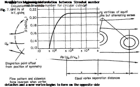
The wake thus consists of a procession of equal-strength vortices, equally spaced but alternating in sign. This type of wake, which can occur behind all long cylinders of bluff cross-section, including flat plates normal to the flow direction, is termed a von Karman vortex street or trail (see Fig. 7.17a). In a uniform stream flowing past a cylinder the vortices move downstream at a speed somewhat less than the free – stream velocity, the reduction in speed being inversely proportional to the streamwise distance separating alternate vortices.

It will be appreciated that, during the formation of any single vortex while it is bound to the cylinder, an increasing circulation will exist about the cylinder, with the consequent generation of a transverse (lift) force. With the development of each successive vortex this force will change sign, giving rise to an alternating transverse force on the cylinder at the same frequency as the vortex shedding. If the frequency happens to coincide with the natural frequency of oscillation of the cylinder, however it may be supported, then appreciable vibration may be caused. This phenomenon is responsible, for example, for the singing of telegraph wires in the wind (Aeolian tones).

A unique relationship is found to exist between the Reynolds number and a dimensionless parameter involving the shedding frequency. This parameter, known as the Strouhal number, is defined by the expression S = nDjUoo, where n is the frequency of vortex shedding. Figure 7.17b shows the typical variation of 5 with Re in the vortex street range.

Despite the many other changes, described below, which occur in the flow pattern as Re increases still further, markedly periodic vortex shedding remains a character­istic flow around the circular cylinder and other bluff bodies up to the highest Reynolds numbers. This phenomenon can have important consequences in engineer­ing applications. An example was the Tacoma Narrows Bridge (in Washington State, U. S.A.) A natural frequency of the bridge deck was close to its shedding frequency causing resonant behaviour in moderate winds, although its collapse in 1940 was due to torsional aeroelastic instability excited by stronger winds.

For two ranges of Reynolds number, namely 200 < Re < 400 and 3 x 10⁵ < Re < 3 x 10⁶, the regularity of vortex shedding is greatly diminished. In the former range very considerable scatter occurs in values of Strouhal number, while for the latter range all periodicity disappears except very close to the cylinder. The values of Reynolds number marking the limits of these two ranges are associated with pronounced changes in the flow pattern. In the case of Re ~ 400 and 3 x 10⁶ the transitions in flow pattern are such as to restore periodicity.

Below Re ~ 200 the vortex street persists to great distances downstream. Above this Reynolds number, transition to turbulent flow occurs in the wake thereby destroying the periodic vortex wake far downstream. At this Reynolds number the vortex street also becomes unstable to three-dimensional disturbances leading to greater irregularity.

At Re ~ 400 a further change occurs. Transition to turbulence now occurs close to the separation points on the cylinder. Rather curiously, perhaps, this has a stabilizing

(a) Re0 = 15000


Flow past cylinders and spheres

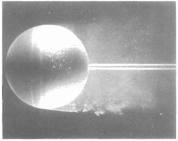
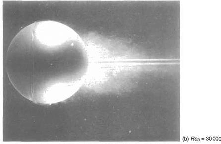
Fig. 7.18 Flow past a sphere: In both cases the flow is from left to right. ReD = 15 000 for (a) which uses dye in water to show a laminar boundary layer separating ahead of the equator and remaining laminar for almost one radius before becoming turbulent. This case corresponds to Fig. 7.15d on page 400. Air bubbles in water provide the flow visualization in (b). For this case ReD = 30000 and a wire hoop on the downstream surface trips the boundary layer ensuring that transition occurs in the separation bubble leading to reattachment and a final turbulent separation much further rearward. This case corresponds to Fig. 7.15e on page 400. The much reduced wake in (b) as compared with (a) leads to a dramatically reduced drag. The use of a wire hoop to promote transition artificially produces the drag reduction at a much lower Reynolds number than for the smooth sphere. (The photographs were taken by H. Werlb at ONERA, France.)


Flow past cylinders and spheres

effect on the shedding frequency even though the vortices themselves develop con­siderable irregular fluctuations. This pattern with laminar boundary-layer separation and a turbulent vortex wake persists until Re ~ 3 x 10s, and is illustrated in Figs 7.15d and 7.16. Note that with laminar separation the flow separates at points on the front half of the cylinder, thereby forming a large wake and producing a high-level of form drag. In this case, the contribution of skin-friction drag is all but negligible.

When the Reynolds number reaches a value in the vicinity of 3 x 10s the laminar boundary layer undergoes transition to turbulence almost immediately after separ­ation. The increased mixing re-energizes the separated flow causing it to reattach as a turbulent boundary layer, thereby forming a separation bubble (as described in Section 7.4.1) – see Figs 7.15e and 7.18.

At this critical stage the second and final point of separation, which now takes place in a turbulent layer, moves suddenly downstream, because of the better sticking property of the turbulent layer, and the wake width is very appreciably decreased. This stage is therefore accompanied by a sudden decrease in the total drag of the cylinder. For this reason the value of Re at which this transition in flow pattern occurs is often called the Critical Reynolds number. The wake vorticity remains random with no clearly discernible frequency. With further increase in Reynolds number the wake width will gradually increase to begin with, as the turbulent separation points slowly move upstream round the rear surface. The total drag continues to increase steadily in this stage, due to increases in both pressure and skin-friction drag, although the drag coefficient, defined by

Подпись: CDdrag per unit span

{PooUlD tends to become constant, at about 0.6, for values of Re > 1.3 x 10⁶. The final change in the flow pattern occurs at Re ~ 3 x 10⁶ when the separation bubble disappears, see Fig. 7.15f. This transition has a stabilizing effect on the shedding frequency which becomes discernible again. Си rises slowly as the Reynolds number increases beyond 3 x 10⁶.

The actual value of the Reynolds number at the critical stage when the dramatic drag decrease occurs depends, for a smooth cylinder, on the small-scale turbulence level existing in the oncoming free stream (see Fig. 7.18). Increased turbulence, or, alternatively, increased surface roughness, will provoke turbulent reattachment, with its accompanying drag decrease, at a lower Reynolds number. The behaviour of a smooth sphere under similarly varying conditions exhibits the same characteristics as the cylinder, although the Reynolds numbers corresponding to the changes of flow regime are somewhat different. One marked difference in behaviour is that the eddying vortex street, typical of bluff cylinders, does not develop in so regular a fashion behind a sphere. Graphs showing the variations of drag coefficient with Reynolds number for circular cylinders and spheres are given in Fig. 7.19.

Separation bubbles

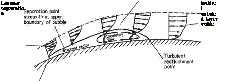
On many aerofoils with relatively large upper-surface curvatures, high local curva­ture over the forward part of the chord may initiate a laminar separation when the aerofoil is at quite a moderate angle of incidence (Fig. 7.14).

Small disturbances grow much more readily and at low Reynolds numbers in separated, as compared to attached, boundary layers. Consequently, the separated laminar boundary layer may well undergo transition to turbulence with characteristic rapid thickening. This rapid thickening may be sufficient for the lower edge of the, now-turbulent, shear layer to come back into contact with the surface and re-attach as a turbulent boundary layer on the surface. In this way, a bubble of fluid is trapped under the separated shear layer between the separation and re-attachment points. Within the bubble, the boundary of which is usually taken to be the streamline that leaves the surface at the separation point, two regimes exist. In the upstream region a pocket of stagnant fluid at constant pressure extends back some way and behind this a circulatory motion develops as shown in Fig. 7.14, the pressure in this latter region increasing rapidly towards the re-attachment point.

Two distinct types of bubble are observed to occur:

(i) a short bubble of the order of 1 per cent of the chord in length (or 100 separation – point displacement thicknesses*) that exerts negligible effect on the peak suction value just ahead of the bubble.

(ii) a long bubble that may be of almost any length from a few per cent of the chord (10 000 separation displacement thicknesses) up to almost the entire chord, which exerts a large effect on the value of the peak suction near the aerofoil leading edge.

It has been found that a useful criterion, as to whether a short or long bubble is formed, is the value at the separation point of the displacement-thickness Reynolds number Rep — Ue6*/v. If Rep < 400 then a long bubble will almost certainly form,

Separation bubbles

Fig. 7.14

Displacement thickness 6* is defined in Section 7.3.2.

while for values >550 a short bubble is almost certain. In between these values either type may occur. This is the Owen-Klanfer[36] criterion.

Short bubbles exert very little influence on the pressure distribution over the aerofoil surface and remain small, with increasing incidence, right up to the stall. They will, in general, move slowly forward along the upper surface as incidence is increased. The final stall may be caused by forward movement of the rear turbulent separation point (trailing-edge stall) or by breakdown of the small bubble at the leading edge owing to failure, at high incidence, of the separated shear flow to re-attach (leading-edge stall).

If a long bubble forms at moderate incidence, its length will rapidly increase with increasing incidence, causing a continuous reduction of the leading-edge suction peak. The bubble may ultimately extend right to the trailing edge or even into the wake downstream, and this condition results in a low lift coefficient and effective stalling of the aerofoil. This type of progressive stall usually occurs with thin aerofoils and is often referred to as thin-aerofoil stall. There are thus three alternative mechan­isms that may produce subsonic stalling of aerofoil sections.

Boundary-layer separation

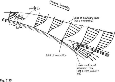
The behaviour of a boundary layer in a positive pressure gradient, i. e. pressure increasing with distance downstream, may be considered with reference to Fig. 7.13. This shows a length of surface that has a gradual but steady convex curvature, such as the surface of an aerofoil beyond the point of maximum thickness. In such a flow region, because of the retardation of the mainstream flow, the pressure in the main­stream will rise (Bernoulli’s equation). The variation in pressure along a normal to the surface through the boundary-layer thickness is essentially zero, so that the pressure at any point in the mainstream, adjacent to the edge of the boundary layer, is transmitted unaltered through the layer to the surface. In the light of this, consider the small element of fluid (Fig. 7.13) marked ABCD. On face AC, the pressure is p, while on face BD the pressure has increased to p + (dp/dx)6.x. Thus the net pressure force on the element is tending to retard the flow. This retarding force is in addition to the viscous shears that act along AB and CD and it will continuously slow the element down as it progresses downstream.

This slowing-down effect will be more pronounced near the surface where the elements are more remote from the accelerating effect, via shearing actions, of the mainstream, so that successive profile shapes in the streamwise direction will change in the manner shown.

Ultimately, at a point S on the surface, the velocity gradient (du/dy)w becomes zero. Apart from the change in shape of the profile it is evident that the boundary layer must thicken rapidly under these conditions, in order to satisfy continuity within the boundary layer. Downstream of point S, the flow adjacent to the surface will be in an upstream direction, so that a circulatory movement, in a plane normal to the surface, takes place near the surface. A line (shown dotted in Fig. 7.13) may be drawn from the point S such that the mass flow above this

Boundary-layer separation

line corresponds to the mass flow ahead of point S. The line represents the continuation of the lower surface of the upstream boundary layer, so that, in effect, the original boundary layer separates from the surface at point S. This is termed the separation point.

Reference to the velocity profiles for laminar and turbulent layers (Fig. 7.4) will make it clear that, owing to the greater extent of lower-energy fluid near the surface in the laminar boundary layer, the effect of a positive pressure gradient will cause separation of the flow much more rapidly than if the flow were turbulent. A turbulent boundary layer is said to stick to the surface better than a laminar one.

The result of separation on the rear half of an aerofoil is to increase the thickness of the wake flow, with a consequent reduction in the pressure rise that should occur near the trailing edge. This pressure rise means that the forward-acting pressure force components on the rear part of the aerofoil do not develop to offset the rearward­acting pressures near the front stagnation point, in consequence the pressure drag of the aerofoil increases. In fact, if there were no boundary layers, there would be a stagnation point at the trailing edge and the boundary-layer pressure drag, as well as the skin-friction drag, would be zero. If the aerofoil incidence is sufficiently large, the separation may take place not far downstream of the maximum suction point, and a very large wake will develop. This will cause such a marked redistribution of the flow over the aerofoil that the large area of low pressure near the upper-surface leading edge is seriously reduced, with the result that the lift force is also greatly reduced. This condition is referred to as the stall. A negative pressure gradient will obviously have the reverse effect, since the streamwise pressure forces will cause energy to be added to the slower-moving air near the surface, decreasing any tendency for the layer adjacent to the surface to come to rest.

Solution for the general case

The solution of the boundary-layer equations for the flat plate described in Section 7.3.4 is a very special case. Although other similarity solutions exist (i. e. cases where the boundary-layer equations reduce to an ordinary differential equation), they are of limited practical value. In general, it is necessary to solve Eqns (7.7) and (7.14) or, equivalently Eqn (7.29), as partial differential equations.

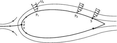
To fix ideas, consider the flow over an aerofoil, as shown in Fig. 7.12. Note that the boundary-layer thickness is greatly exaggerated. The first step is to determine the potential flow around the aerofoil. This would be done computationally by using the panel method described in Section 3.6 for non-lifting aerofoils or Section 4.10 in the case where lift is generated. From this solution for the potential flow the velocity Ue along the surface of the aerofoil can be determined. This will be assumed to be the velocity at the edge of the boundary layer. The location of the fore stagnation point F can also be determined from the solution for Ue. Plainly it corresponds to Ue = 0. (For the non-lifting case of a symmetric aerofoil at zero angle of attack the location of the fore stagnation point will be known in advance from symmetry). This point corresponds to x = 0. And the development of the boundary layers over the top and bottom of the aerofoil have to be calculated separately, unless they are identical, as in symmetric aerofoils at zero incidence.

Mathematically, the boundary-layer equations are parabolic. This means that their solution (i. e. the boundary-layer velocity profile) at an arbitrary point P[, say, (where x = xi) on the aerofoil depends only on the solutions upstream, i. e. at x < X[. This property allows special efficient numerical methods to be used whereby one begins with the solution at the fore stagnation point and marches step by step around the aerofoil, solving the boundary-layer equations at each value of x in turn. This is very much easier than solving the Navier-Stokes equations that in subsonic steady flow are elliptic equations like the Laplace equation. The term elliptic implies that the solution (i. e. the velocity field) at a particular point depends on the solutions at all other points. For elliptic equations the flow field upstream does depend on condi­tions downstream. How else would the flow approaching the aerofoil sense its presence and begin gradually to deflect from uniform flow in order to flow smoothly

Solution for the general case

Fig. 7.12 The boundary layer developing around an aerofoil


around the aerofoil? Nevertheless, numerical solution of the boundary-layer equations is not particularly simple. In order to avoid numerical instability, so-called implicit methods are usually required. These are largely beyond the scope of the present book, but are described in a simple treatment given below in Section 7.11.3.

For aerofoils and other bodies with rounded leading edges, the stagnation flow field determined in Section 2.10.3 gives the initial boundary-layer velocity profile in the vicinity of. v = 0. The velocity Ue along the edge of the boundary layer increases rapidly away from the fore stagnation point, F. The evolving velocity profile in the boundary layer is found by solving the boundary-layer equations step by step by ‘marching’ around the surface of the aerofoil. At some point i/e will reach a max­imum at the point of minimum pressure. From this point onwards the pressure gradient along the surface will change sign to become adverse and begin to slow down the boundary-layer flow (as explained above in Section 7.2.6 and below in Section 7.4). A point of inflexion develops in the velocity profile (e. g. at point P2 in Fig. 7.12, see also Fig. 7.6) that moves towards the wall as. x increases. Eventually, the inflexion point reaches the wall itself, the shear stress at the wall falls to zero, reverse flow occurs (see Fig. 7.6), and the boundary layer separates from the surface of the aerofoil at point S. The boundary-layer equations cease to be valid just before separation (where rw = p(du/dy)w = 0) and the calculation is terminated.

Overall the same procedure’s are involved when using the approximate methods described in Section 7.11 below. There a more detailed account of the computation of the boundary layer around an aerofoil will be presented.

Solution of the boundary-layer equations for a flat plate

There are a few special exact solutions of the boundary-layer equations (7.7) and

(7.14) . The one for the boundary layer in the vicinity of a stagnation point is an exact solution of the Navier-Stokes equations and was described in Section 2.10.3. In this case, we saw that an exact solution was interpreted as meaning that the governing equations are reduced to one or more ordinary differential equations. This same interpretation carries over to the boundary-layer equations. The most famous, and probably most useful, example is the solution for the boundary layer over a flat plate (see Fig. 7.7). This was first derived by one of Prandd’s PhD students, Blasius, in 1908.

Подпись: (7.28a,b)
Solution of the boundary-layer equations for a flat plate

A useful starting point is to introduce the stream function, ф, (see Section 2.5 and Eqns 2.56a, b) such that

This automatically satisfies Eqn (7.7), reducing the boundary-layer equations to a single equation (7.14) that takes the form:

Подпись: (7.29)дф д2ф сРф 1 djр д3ф

ду дхду дх ду2 р dx V ду3

For the flat plate dp/dx = 0.

Consider the hypothetical case of an infinitely long flat plate. For practical appli­cation we can always assume that the boundary layer at a point x = L, say, on an infinitely long plate is identical to that at the trailing edge of a flat plate of length L. But, if the hypothetical plate is infinitely long, we cannot use its length as a reference dimension. In fact, the only length dimension available is v/lloo. This strongly suggests that the boundary layer at a point xi, say, will be identical to that at another point *2, except that the boundary-layer thicknesses will differ. Accordingly we

Solution of the boundary-layer equations for a flat plate Solution of the boundary-layer equations for a flat plate

propose that, as suggested in Fig. 7.7, the velocity profile does not change shape as the boundary layer develops along the plate. That is, we can write

Подпись: {x,y) Solution of the boundary-layer equations for a flat plate

We now tranform the independent variables

so that

Ш,

Solution of the boundary-layer equations for a flat plate

=i

Likewise, if we replace ф by дф/ду in Eqn (7.33) and make use of Eqn (7.36), we obtain

Подпись:сРф

дхду

Similarly using Eqn (7.34) and (7.36)

Подпись:^Ф_д_(9ф_д_(и V=^-l/2u dV

ду2 дуду) dy 00 dr,) ^ 00 drj2

дуъ «« и«>^

Solution of the boundary-layer equations for a flat plate
We now substitute Eqns (7.36)-{7.40) into Eqn (7.29) to obtain

Solution of the boundary-layer equations for a flat plate Подпись: (7.41)

Then cancelling common factors and rearranging leads to

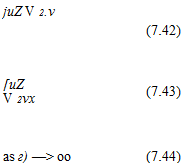
As suggested, if we wish to obtain the simplest universal (i. e. independent of the values of Uoo and v) form of Eqn (7.41), we should set

Подпись: juZ V 2.v (7.42) [uZ V 2vx (7.43) as г) —> oo (7.44) Uaо….

2ua2

So that Eqn (7.41) reduces to

Подпись:^+/^ = 0- dr^ drj2 ’

The boundary conditions (7.15) become

Подпись:Подпись: 0 at r) = 0; / —> 1 as r,Л

drj

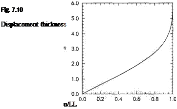
The ordinary differential equation can be solved numerically for /. The velocity profile d//d?7 thus obtained is plotted in Fig. 7.10 (see also Fig. 7.11).

From this solution the various boundary-layer thicknesses given in Section 7.3.2 can be obtained by evaluating the integrals numerically in the forms:

1.7208

Подпись: (7.47)
Solution of the boundary-layer equations for a flat plate

Momentum thickness Energy thickness

°=ГН’-й>=&Ш’ – (I) V ‘W£ ™

The local wall shear stress and hence the skin-friction drag can also be calculated readily from function f(rf):

fdu drj (du

Подпись: (7.49)

Solution of the boundary-layer equations for a flat plate Подпись: (7.46)

_ TJ ux(d2f ux

— ( j 7 I 0.332fJiUoQl

V 2vx drf)^ V их

4—– v—– ‘

0.332V7

Solution of the boundary-layer equations for a flat plate

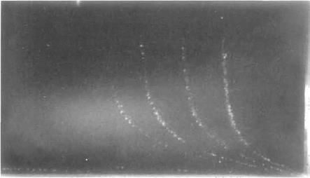
Fig. 7.11 Velocity profile in a boundary layer: The velocity profile that forms in a boundary layer along a flat wall is made visible by lines of aluminium powder dropped from a trough on to the flowing fluid surface. The fluid is a dilute solution of wallpaper paste in water. The Reynolds number based on distance along the wall is about 50000. See also Fig. 7.3 on page 376. (The photograph was taken by D. J. Buckingham at the School of Engineering, University of Exeter, UK.)


Solution of the boundary-layer equations for a flat plate

Thus the skin-friction coefficient is given by

Solution of the boundary-layer equations for a flat plate
Thus combining Eqns (7.49) and (7.51) we find that the drag of one side of the plate is given by

Example 7.2 The Blasius solution for the laminar boundary layer over a flat plate will be used to estimate the boundary-layer thickness and skin-friction drag for the miniature wing of Example 7.1.

The Reynolds number based on length Лгу, = 2000, so according to Eqns (7.45) and (7.46) the boundary-layer thicknesses at the trailing edge are given by

Solution of the boundary-layer equations for a flat plate

1 7208

6* = —^— x 0.67 = 0.23 mm

Solution of the boundary-layer equations for a flat plate

5


Remembering that the wing has two sides, an estimate for its skin-friction drag is given by

Подпись: ytdvdy in-61 і 1.328 j

Df = 2 x CCF x – t/2.SZ, = . x 1.2 x 52

г иг ~ aa /onnn

Skin friction drag

The shear stress between adjacent layers of fluid in a laminar flow is given by r = p(du/dy) where du/dy is the transverse velocity gradient. Adjacent to the solid surface at the base of the boundary layer, the shear stress in the fluid is due entirely to viscosity and is given by p,(du/dy)v. This statement is true for both

laminar and turbulent boundary layers because, as discussed in Section 7.2.4, a viscous sublayer exists at the surface even if the main boundary-layer flow is turbulent. The shear stress in the fluid layer in contact with the surface is essentially the same as the shear stress between that layer and the surface so that for all boundary layers the shear stress at the wall, due to the presence of the boundary layer, is given by

Подпись: (7.19)’■’“"(I),

where tw is the wall shear stress or surface friction stress, usually known as the skin friction.

Once the velocity profile (laminar or turbulent) of the boundary layer is known, then the surface (or skin) friction can be calculated. The skin-friction stress can be defined in terms of a non-dimensional local skin-friction coefficient, Q, as follows.

т„ = Сі1-РиІ (7.20)

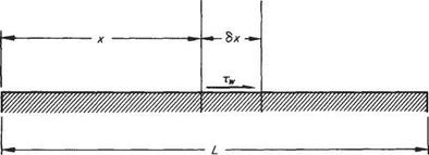
Of particular interest is the total skin-friction force F on the surface under consideration. This force is obtained by integrating the skin-friction stress over the surface. For a two-dimensional flow, the force F per unit width of surface may be evaluated, with reference to Fig. 7.9, as follows. The skin-friction force per unit width on an elemental length (6x) of surface is

6F = tw6x

Therefore the total skin-friction force per unit width on length L is

Подпись: Twdx(7.21)

The skin-friction force F may be expressed in terms of a non-dimensional coeffi­cient Cp, defined by

Подпись: (7.22)

Skin friction drag

F=CF^pUlSw

where Sw is the wetted area of the surface under consideration. Similarly for a flat plate or aerofoil section, the total skin-friction drag coefficient Сдр is defined by

Подпись: (7.23)Df = CDf-PUl

Подпись: ■'Df Подпись: IF Подпись: 2CF Подпись: (7.24)

where Df = total skin-friction force on both surfaces resolved in the direction of the free stream, and S = plan area of plate or aerofoil. For a flat plate or symmetrical aerofoil section, at zero incidence, when the top and bottom surfaces behave identi­cally, Df = 2F and S = Sv, (the wetted area for each surface). Thus

When flat-plate flows (at constant pressure) are considered, Ue = U^. Except where a general definition is involved, Ue will be used throughout.

Skin friction drag Подпись: (7.25)

Subject to the above condition, use of Eqns (7.20) and (7.22) in Eqn (7.21) leads to

Equation (7.25) is strictly applicable to a flat plate only, but on a slim aerofoil, for which Ue does not vary greatly from over most of the surface, the expression will give a good approximation to Cf-

We have seen in Eqn (7.11) how the boundary-layer thickness varies with Reynolds number. This result can also be used to show how skin friction and skin-friction drag varies with ReL. Using the order-of-magnitude estimate (7.3) it can be seen that

du /j, Ue p>Ux /——

tw = р,— ос – г – oc ——- y/ReL
ду о L

Skin friction drag Подпись: (7.26)

But, by definition, ReL = pUxLjp, so the above becomes

Skin friction drag Подпись: and Skin friction drag Подпись: (7.27)

It therefore follows from Eqns (7.20) and (7.25) that the relationships between the coefficients of skin-friction and skin-friction drag and Reynolds number are identical and given by

Example 7.1 Some engineers wish to obtain a good estimate of the drag and boundary-layer thickness at the trailing edge of a miniature wing. The chord and span of the wing are 6 mm and 30 mm respectively. A typical flight speed is 5m/s in air (kinematic viscosity = 15 x 10~6 m2/s, density =1.2 kg/m3). They decide to make a superscale model with chord and span of 150 mm and 750 mm respectively. Measurements on the model in a water channel flowing at 0.5m/s (kinematic viscosity = 1 x 10⁻⁶ m2/s, density = 1000kg/m3) gave a drag of 0.19N and a boundary-layer thickness of 3 mm. Estimate the corresponding values for the prototype.

Skin friction drag Skin friction drag

The Reynolds numbers of model and prototype are given by

Skin friction drag

Evidently, the Reynolds numbers are not the same for model and prototype, so the flows are not dynamically similar. But, as a streamlined body is involved, we can use Eqns (7.11) and (7.27). From Eqn (7.11)

and from Eqn (7.27)

1/2

Подпись: D _D (PUIS)P ({ReL)m D^Dm(PUlS)m{(ReL)p Skin friction drag Skin friction drag

But D[ = і pU^SCof. So, if we assume that skin-friction drag is the dominant type of drag and that it scales in the same way as the total drag, the prototype drag is given by

Various definitions of boundary-layer thickness

In the course of deriving the boundary-layer equations we have shown in Eqn (7.11) how the boundary-layer thickness varies with Reynolds number. This is another example of obtaining useful practical information from an equation without needing to solve it. Its practical use will be illustrated later in Example 7.1. Notwithstanding such practical applications, however, we have already seen that the boundary-layer thickness is rather an imprecise concept. It is difficult to give it a precise numerical value. In order to do so in Section 7.2.2 it was necessary, rather arbitrarily, to identify the edge of the boundary layer as corresponding to the point where и = 0.99f/e. Partly owing to this rather unsatisfactory vagueness, several more precise definitions of boundary-layer thickness are given below. As will become plain, each definition also has a useful and significant physical interpretation relating to boundary-layer characteristics.

Displacement thickness (8*)

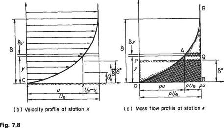
Consider the flow past a flat plate (Fig. 7.8a). Owing to the build-up of the boundary layer on the plate surface a stream tube that, at the leading edge, is close to the surface will become entrained into the boundary layer. As a result the mass flow in the streamtube will decrease from pUe, in the main stream, to some value pu, and – to satisfy continuity – the tube cross-section will increase. In the two-dimensional flows considered here, this means that the widths, normal to the plate surface, of the boundary-layer stream tubes will increase, and stream tubes that are in the main­stream will be displaced slightly away from the surface. The effect on the mainstream flow will then be as if, with no boundary layer present, the solid surface had been displaced a small distance into the stream. The amount by which the surface would be displaced under such conditions is termed the boundary-layer displacement thick­ness (6*) and may be calculated as follows, provided the velocity profile u =f{y) (see Fig. 7.3) is known.

At station x (Fig. 7.8c), owing to the presence of the boundary layer, the mass flow rate is reduced by an amount equal to

Various definitions of boundary-layer thickness

corresponding to area OABR. This must equate to the mass flow rate deficiency that would occur at uniform density p and velocity Ue through the thickness 6*, corres­ponding to area OPQR. Equating these mass flow rate deficiencies gives

Various definitions of boundary-layer thickness

i. e.

Various definitions of boundary-layer thickness

(a)


Various definitions of boundary-layer thickness

The idea of displacement thickness has been put forward here on the basis of two-dimensional flow past a flat plate purely so that the concept may be considered in its simplest form. The above definition may be used for any incompressible two­dimensional boundary layer without restriction and will also be largely true for boundary layers over three-dimensional bodies provided the curvature, in planes normal to the free-stream direction, is not large, i. e. the local radius of curvature should be much greater than the boundary-layer thickness. If the curvature is large a displacement thickness may still be defined but the form of Eqn (7.16) will be slightly modified. An example of the use of displacement thickness will be found later in this chapter (Examples 7.2 and 7.3).

Similar arguments to those given above will be used below to define other boundary-layer thicknesses, using either momentum flow rates or energy flow rates.

Momentum thickness (в)

This is defined in relation to the momentum flow rate within the boundary layer. This rate is less than that which would occur if no boundary layer existed, when the velocity in the vicinity of the surface, at the station considered, would be equal to the mainstream velocity Ue.

For the typical streamtube within the boundary layer (Fig. 7.8b) the rate of momentum defect (relative to mainstream) is pu{Ut — u)6y. Note that the mass flow rate pu actually within the stream tube must be used here, the momentum defect of this mass being the difference between its momentum based on mainstream velocity and its actual momentum at position x within the boundary layer.

The rate of momentum defect for the thickness в (the distance through which the surface would have to be displaced in order that, with no boundary layer, the total flow momentum at the station considered would be the same as that actually occurring) is given by pU&. Thus:

Подпись: r Jo pu(Ue – u)dy = pUB

i. e.

*-f£ (7Л7>

The momentum thickness concept is used in the calculation of skin friction losses.

Kinetic energy thickness (8**)

This quantity is defined with reference to kinetic energies of the fluid in a manner comparable with the momentum thickness. The rate of kinetic-energy defect within the boundary layer at any station x is given by the difference between the energy that the element would have at main-stream velocity t/e and that it actually has at velocity u, being equal to

Подпись: r Jo > і

~pu(Ul – u*)dy /о L

while the rate of kinetic-energy defect in the thickness 6** is pU6**. Thus

П pu{Ul-f)&y = pUlsr Jo

Подпись: = r±l(±) Jo Ue UJ Подпись: dу Подпись: (7.18)

i. e.

Derivation of the laminar boundary-layer equations

At high Reynolds numbers the boundary-layer thickness, 6, can be expected to be very small compared with the length, L, of the plate or streamlined body. (In aeronautical examples, such as the wing of a large aircraft 6)L is typically around 0.01 and would be even smaller if the boundary layer were laminar rather than turbulent.) We will assume that in the hypothetical case of ReL —> oo (where ReL = pUxLjp), <5 —> 0. Thus if we introduce the small parameter

Подпись: (7.1) (7.2) 1

“ ReL

we would expect that 6 —> 0 as є —> 0, so that

cx є

where n is a positive exponent that is to be determined.

Suppose that we wished to estimate the magnitude of velocity gradient within the laminar boundary layer. By considering the changes across the boundary layer along line AB in Fig. 7.7, it is evident that a rough approximation can be obtained by writing

du ^ Uao _ Uqq 1 dy~ 6 L є”

Derivation of the laminar boundary-layer equations

Fig. 7.7

Although this is plainly very rough, it does have the merit of remaining valid as the Reynolds number becomes very high. This is recognized by using a special symbol for the rough approximation and writing

Подпись: dy  L e"Jdy

For the more general case of a streamlined body (e. g. Fig. 7.1), we use x to denote the distance along the surface from the leading edge (strictly from the fore stagnation point) and у to be the distance along the local normal to the surface. Since the boundary layer is very thin and its thickness much smaller than the local radius of curvature of the surface, we can use the cartesian form, Eqns (2.92a, b) and (2.93), of the Navier-Stokes equations. In this more general case, the velocity varies along the edge of the boundary layer and we denote it by Ue, so that

Подпись: du dy (7.3)

where Ue replaces иж, so that Eqn (7.3) applies to the more general case of a boundary layer around a streamlined body. Engineers think of G(Ue/6) as meaning order of magnitude of Ue/6 or very roughly a similar magnitude to Ue/6. To math – ematicans F = 0(1/єп) means that F oc l/є" as є —> 0. It should be noted that the order-of-magnitude estimate is the same irrespective of whether the term is negative or positive.

Estimating du/dy is fairly straightforward, but what about du/dxl To estimate this quantity consider the changes along the line CD in Fig. 7.7. Evidently, и = Ux at C and и —> 0 as D becomes further from the leading edge of the plate. So the total change in и is approximately!/«, — 0 and takes place over a distance Ax ~ L. Thus for the general case where the flow velocity varies along the edge of the boundary layer, we deduce that

Подпись:(7.4)

Finally, in order to estimate second derivatives like d2u/dy2, we again consider the changes along the vertical line AB in Fig. 7.7. At В the estimate (7.3) holds for du/dy whereas at A, du/dy — 0. Therefore, the total change in du/dy across the boundary layer is approximately (U^/S) — 0 and occurs over a distance <5. So, making use of Eqn (7.1), in the general case we obtain

Подпись: ™ = o№)=o№±) dy2- WS2J ^L2 Є2") cPu

Подпись: Ue Подпись: (7.6) Подпись: dx2 Z,2/

In a similar way we deduce that

Подпись: F =0 dy Подпись: (7.7) Подпись: du d(Uc/L)
Подпись: o(v/(e»L))
Подпись: If both terms are the same order of magnitude we can deduce from Eqn (7.7) that 6
Подпись: v = 0(ue^=0(ueen)
Подпись: (7.8)

We can now use the order-of-magnitude estimates (7.3)-(7.6) to estimate the order of magnitude of each of the terms in the Navier-Stokes equations. We begin with the continuity Eqn (2.93)

One might question the assumption that two terms are the same order of magnitude. But, the slope of the streamlines in the boundary layer is equal to v/u by definition and will also be given approximately by b/L, so Eqn (7.8) is evidently correct.

0(Ul/L) 0{Xfi/L) dv dv

з+ % –

0{ЄЧ/ЦЬ) 0{e*Ul/L)

+ -1^1 + *%) <7’9>

O(unknown) 0(vUe/L2)=0(EU%/L) 0(i/£/e/(L2e2n))=0(Ei-2»U|/i)

Derivation of the laminar boundary-layer equations

We will now use Eqns (7.3)-(7.6) and (7.8) to estimate the orders of magnitude of the terms in the Navier-Stokes equations (2.92a, b). We will assume steady flow, ignore the body-force terms, and divide throughout by p (noting that the kinematic viscosity v = р/р), thus

Now є = 1/ReL is a very small quantity so that a quantity of 0(eU2/L) is negligible compared with one of 0(U%/L). It therefore follows that the second term on the right-hand side of Eqn (7.9) can be dropped in comparison with the terms on the left – hand side. What about the third term on the right-hand side of Eqn (7.9)? If 2л = 1 it will be the same order of magnitude as those on the left-hand side. If 2л < 1 then this remaining viscous term will be negligible compared with the left-hand side. This cannot be so, because we know that the viscous effects are not negligible within the boundary layer. On the other hand, if 2л > 1 the terms on the left-hand side of Eqn (7.9) will be negligible in comparison with the remaining viscous term. So, for the flat plate for which dp/dx = 0, Eqn (7.9) reduces to

Подпись:c9u dy2

This can be readily integrated to give

u=f(x)y + g(x)

Note that, as it is a partial derivative, arbitrary functions of x, f(x) and g(x), take the place of constants of integration. In order to satisfy the no-slip condition (и = 0) at the surface, у = 0, g(x) = 0, so that и ос у. Evidently this does not conform to the required smooth velocity profile depicted in Figs 7.3 and 7.7. We therefore conclude that the only possiblity that fits the physical requirements is

Подпись:Подпись: (7.12)2n = 1 implying 6 ос є1/2 -^L=)

and Eqn (7.9) simplifies to

Подпись: 1 dp /сі2и p dx Vdy2)du du

u—+ v— : dx dy

It is now plain that all the terms in Eqn (7.10) must be 0(el^2Ul/L) or even smaller and are therefore negligibly small compared to the terms retained in Eqn (7.12). We therefore conclude that Eqn (7.10) simplifies drastically to

Подпись:dy

Derivation of the laminar boundary-layer equations Подпись: (7.14)

In other words, the pressure does not change across the boundary layer. (In fact, this could be deduced from the fact that the boundary layer is very thin, so that the streamlines are almost parallel with the surface.) This implies that p depends only on x and can be determined in advance from the potential-flow solution. Thus Eqn (7.12) simplifies further to

Equation (7.14) plus (7.7) are usually known as the (Prandtl) boundary-layer equations.

To sum up, then, the velocity profiles within the boundary layer can be obtained as follows:

(i)Determine the potential flow around the body using the methods described in Chapter 3;

(ii) From this potential-flow solution determine the pressure and the velocity along the surface;

(iii) Solve equations (7.7) and (7.14) subject to the boundary conditions

Подпись: (7.15)u = v = 0 at = 0; и = Ue at у — 6 (or oo)

The boundary condition, и = 0, is usually referred to as the по-slip condition because it implies that the fluid adjacent to the surface must stick to it. Explanations can be offered for why this should be so, but fundamentally it is an empirical observation. The second boundary condition, v = 0, is referred to as the no-penetration condition because it states that fluid cannot pass into the wall. Plainly, it will not hold when the surface is porous, as with boundary-layer suction (see Section 8.4.1). The third boundary condition (7.15) is applied at the boundary-layer edge where it requires the flow velocity to be equal to the potential-flow solution. For the approximate methods described in Section 7.7, one usually applies it at у = S. For accurate solutions of the boundary-layer equations, however, no clear edge can be defined;

the velocity profile is such that и approaches ever closer to Ue the larger у becomes. Thus for accurate solutions one usually chooses to apply the boundary condition at у = oo, although it is commonly necessary to choose a large finite value of у for seeking computational solutions.

The boundary-layer equations

To fix ideas it is helpful to think about the flow over a flat plate. This is a particularly simple flow, although like much else in aerodynamics the more one studies the details the less simple it becomes. If we consider the case of infinite Reynolds number,

i. e. ignore viscous effects completely, the flow becomes exceedingly simple. The stream­lines are everywhere parallel to the flat plate and the velocity uniform and equal to Uqo, the value in the free stream infinitely far from the plate. There would, of course, be no drag, since the shear stress at the wall would be equivalently zero. (This is a special case of d’Alembert’s paradox that states that no force is generated by irrota – tional flow around any body irrespective of its shape.) Experiments on flat plates would confirm that the potential (i. e. inviscid) flow solution is indeed a good approximation at high Reynolds number. It would be found that the higher the Reynolds number, the closer the streamlines become to being everywhere parallel with the plate. Furthermore, the non-dimensional drag, or drag coefficient (see Section 1.4.5), becomes smaller and smaller the higher the Reynolds number becomes, indicating that the drag tends to zero as the Reynolds number tends to infinity.

But, even though the drag is very small at high Reynolds number, it is evidently important in apphcations of aerodynamics to estimate its value. So, how may we use this excellent infinite-Reynolds-number approximation, i. e. potential flow, to do this? Prandtl’s boundary-layer concept and theory shows us how this may be achieved. In essence, he assumed that the potential flow is a good approximation everywhere except in a thin boundary layer adjacent to the surface. Because the boundary layer is very thin it hardly affects the flow outside it. Accordingly, it may be assumed that the flow velocity at the edge of the boundary layer is given to a good approximation by the potential-flow solution for the flow velocity along the surface itself. For the flat plate, then, the velocity at the edge of the boundary layer is Ux. In the more general case of the flow over a streamlined body like the one depicted in Fig. 7.1, the velocity at the edge of boundary layer varies and is denoted by Ut. Prandtl went on to show, as explained below, how the Navier-Stokes equations may be simplified for application in this thin boundary layer.

Effects of an external pressure gradient

In the previous section, it was noted that in most practical aerodynamic applications the mainstream velocity and pressure change in the streamwise direction. This has a profound effect on the development of the boundary layer. It can be seen from Fig. 7.2 that the net streamwise force acting on a small fluid element within the boundary layer is

дт dp 9Ї6у-9-Хвх

When the pressure decreases (and, correspondingly, the velocity along the edge of the boundary layer increases) with passage along the surface the external pressure

Effects of an external pressure gradient

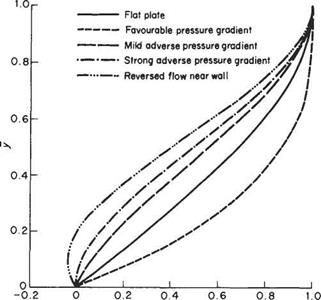
Fig. 7.6 Effect of external pressure gradient on the velocity profile in the boundary layer

gradient is said to be favourable. This is because dpjdx < 0 so, noting that drjdy < 0, it can be seen that the streamwise pressure forces help to counter the effects, dis­cussed earlier, of the shearing action and shear stress at the wall. Consequently, the flow is not decelerated so markedly at the wall, leading to a fuller velocity profile (see Fig. 7.6), and the boundary layer grows more slowly along the surface than for a flat plate.

The converse case is when the pressure increases and mainstream velocity decreases along the surface. The external pressure gradient is now said to be unfavourable or adverse. This is because the pressure forces now reinforce the effects of the shearing action and shear stress at the wall. Consequently, the flow decelerates more markedly near the wall and the boundary layer grows more rapidly than in the case of the flat plate. Under these circumstances the velocity profile is much less full than for a flat plate and develops a point of inflexion (see Fig. 7.6). In fact, as indicated in Fig. 7.6, if the adverse pressure gradient is sufficiently strong or pro­longed, the flow near the wall is so greatly decelerated that it begins to reverse direction. Flow reversal indicates that the boundary layer has separated from the surface. Boundary-layer separation can have profound consequences for the whole flow field and is discussed in more detail in Section 7.4.