Our heavyweight helicopter equal in the world does not have
In Rostov started production of the most load-lifting rotary-wing car The Russian holding «Helicopt[...]

Everything about aircrafts and helicopters. News and events in aviation worldwide. Civil, transportation, military helicopters and airplanes.

Everything about aircrafts and helicopters. News and events in aviation worldwide. Civil, transportation, military helicopters and airplanes.

Everything about aircrafts and helicopters. News and events in aviation worldwide. Civil, transportation, military helicopters and airplanes.

Everything about aircrafts and helicopters. News and events in aviation worldwide. Civil, transportation, military helicopters and airplanes.


We consider first the case when the cruise speed remains constant
in otherwise perturbed motion. In what follows, all quantities and functions will be rendered nondimensional with respect to the cruise speed U0 and the root chord C0 of the main wing of the vehicle. In this case, the equations of perturbed uncontrolled motion of the WIG can be written as
![]()
![]()
![]() d2h 1 dt2 =
d2h 1 dt2 =
d20
Mb-^2 = mz’
where /j, is relative density of the vehicle defined by the formula
2 M pSC0′
|
Iz MC02’ |
In (11.1) and (11.2), Cy and fhz are the perturbed lift and the moment coefficients, h and 6 represent the perturbed relative ground clearance and the pitch angle, M is the vehicle’s mass in cruise, S is the wing’s reference area, p is the specific density of air, and iz is a coefficient of the longitudinal moment of inertia of mass, determined by the relationship
where Iz is the longitudinal moment of inertia of mass with respect to the center of gravity. To track the relationship between the dynamic stability of the vehicle and its cruise speed, it is sometimes convenient to use the following obvious equation:
P — Fr2Cyo, Fr = -^p, (11.5)
where Fr and Cyo are correspondingly the cruise Froude number and the cruise lift coefficient. Accounting for (11.1), (11.2), and (11.5), the (two)
equations of motion with respect to the perturbations of pitch and ground clearance can be written in an alternative form as
|
Fr2C A2’h _ c pr2C – fh *Г ^Уо “ ^2/’ ^yo %z ^2 ~т*’ |
(11.6) |
|
Using a representation of the perturbed lift and the moment coefficients in terms of the derivatives with respect to the principal kinematic parameters 9 and /1, we can write |
|
|
cy = c9e + с* К + с9 ё + c% |
(11.7) |
|
rhz = mez9 + m^h + raf 0 + m^h. (11.8) Now we can rewrite the equations (11.7), (11.8) in the following form: |
|
|
^ ^ Г1*1 ^ Гh — ^ 1 г*о Л ^~Су1л~Сук-СуЦ + Сув’ |
(11.9) |
|
d 4 id6 idh,, "**d?“m’d?“m-e = m’ ii+m’h- |
(11.10) |
|
Excluding h or 9 from the equation set (11.9), (11.10), we obtain the following fourth-order (quartic) characteristic equation of the system: |
|
|
D4 + A1D3 + A2D2 + AZD + A4 = 0, |
(11.11) |
|
where the coefficients Ai(i = 1,2,3,4) are |
|
|
A‘ = – A(mi + i, Ci), ftLz |
(11.12) |
|
A2= 2. [c9mhz СуГп9 + ц(т9 +1 zCy), ft I’z |
(11.13) |
|
A3 = 4~(тІСу + <СІ – С№ – СУ<)> ft 1Z |
(11.14) |
|
■4. = -4гКс;-С,»тЙ, ft Lz |
(11.15) |
The last coefficient can be rewritten to be expressed in terms of the abscissas of the aerodynamic centers of height xh and of pitch 9:
The stability of motion for the fourth-order equation will be ensured if
Ai, Л-2-, Аз, A* > О A2A3 — A1A4 — A3 > 0. (11.17)
It can be shown from consideration of formulas (11.12)-(11.17) that conditions Ai > О, A2 > 0 and As > 0 always hold. Hence, the requirements of stability in proximity to the ground can be reduced to the two inequalities A4 > 0 and A1A2AS — A1A4 — A > 0. Satisfaction of the former condition provides aperiodic stability to the craft, i. e., the absence of positive real roots of the characteristic equation. Meeting the latter requirement ensures oscillatory stability, i. e., the absence of positive real parts of the complex roots of the characteristic equation. It follows immediately from these considerations and observation of (11.16) that to secure the aperiodic stability of wing-inground-effect vehicle, one should select an aerodynamic configuration of the craft for which the center of height is located upstream of the center of pitch, i. e., — xq > 0 (note that here the x axis is directed upstream).
Here, the linearized versions of the equations of longitudinal motion will be deduced, corresponding to what is known as the quartic and the quintic descriptions of the dynamics of wing-in-ground-effect vehicles. In other words, linearized equations of motion and corresponding characteristic equations
are written with and without accounting for perturbation of the forward speed. Instead of the representative kinematic parameters a (angle of attack) and h (relative ground clearance) utilized by Kumar and Staufenbiel, the parameters в (pitch angle) and h (relative ground clearance) will be employed. In what follows, all unsteady aerodynamic derivatives will be incorporated.
The pair of parameters 6,h is more practical in the aerodynamics of ground-effect vehicles than a, h. The use of #, h was first proposed by Treshkov [180] and since has been adopted in most of the Russian developments on wing-in-ground-effect vehicles.
The analysis of the dynamics of wing-in-ground-effect vehicles provides data for assessing the stability of motion, controllability, and ride comfort of the craft under development.
A study of the linearized equations of the motion of wing-in-ground-effect vehicles was carried out by Irodov [166], Kumar [167]—[170], Zhukov [171]— [175], and Staufenbiel et al. [176]-[178]. This research revealed a significant distinction between the dynamics and the stability criteria of these vehicles and the aircraft that normally operates out of the ground effect. It was also found that one of the typical problems of the design of ground-effect machines is due to the strong coupling between their aerodynamic configuration and the flight dynamics.
Irodov[166] considered the linearized equations of perturbed longitudinal motion in terms of the variation of the angle of attack and the ground clearance. Assuming that the speed of the vehicle remains constant, he derived a (quartic) characteristic polynomial equation of the fourth order. Applying the Gurvitz-Ruth criteria of stability, he came to the conclusion that aperiodic static stability is ensured when the aerodynamic center of height is located upstream of that of the angle of attack. This important practical conclusion signifies that if the aerodynamic configuration is not selected properly, it is impossible to secure static longitudinal stability to the motion of a wing-in-ground-effect vehicle by choosing the position of the center of gravity.
According to Irodov [166], to secure the oscillatory stability of the vehicle one has to provide an appropriate location of the center of gravity upstream of the center of the angle of attack. In the same work, Irodov indicated that account of the variation in cruise speed practically does not modify the previously mentioned condition of static aperiodic stability.
Kumar [166] studied the dynamics of a wing-in-ground-effect vehicle in both longitudinal and lateral motion, incorporating the effects connected with perturbation of the speed of forward motion. His stability analysis was based on a quintic characteristic equation.
A thorough study of the dynamics of wing-in-ground-effect vehicles accounting for the perturbation of speed and incorporating stability analy-
K. V. Rozhdestvensky, Aerodynamics of a Lifting System in Extreme Ground Effect © Springer-Verlag Berlin Heidelberg 2000
sis with special reference to controllability[68] and design, was carried out by Zhukov, starting in the 1970s and finalized in [175]. He revealed several distinct parameters, defining static stability and dynamic behavior of wing-inground-effect craft. In particular, he introduced the notion of binding to the ground, as a capability of a vehicle in cruising flight to stay in ground effect after the action of controls or gusts of wind.
Staufenbiel also studied stability criteria, used the quintic characteristic equation for the analysis of the dynamics, and discussed nonlinear effects.
This section covers some linear formulations related to the longitudinal dynamics of wing-in-ground-effect vehicles. First of all, a derivation is given in terms of the perturbations of the relative ground clearance h and the pitch angle в of the linearized equations of motion without (after Irodov) and with (after Zhukov) account of perturbation of forward speed. Then, we consider an approximate derivation of an asymptotic form of the linearized equations of the longitudinal motion of a wing-in-ground effect vehicle in the extreme ground effect, i. e., for vanishing relative clearances between the lifting surface and the ground. The orders of magnitude of the terms are evaluated formally on the basis of a simplified nonlinear unsteady theory of the extreme ground effect, discussed in section 4. Eventually, an asymptotic form of the equations of motion is derived for h —> 0 and small periods of time from the moment of the action of the perturbation. It is shown that on (nondimensional) time scale t = 0(1), which corresponds to distances of the order of the chord from the moment of perturbation, the equations of motion correspond to the quartic formulation of Irodov [166], i. e., the speed of the vehicle remains almost constant. From a practical viewpoint, this signifies that Irodov’s criterion of static stability is valid, although it was derived on the basis of the somewhat restrictive assumption of no perturbation of speed. Differing from Irodov, the asymptotic form of the equation, valid for a vanishing /і, does not depend explicitly on the relative ground clearance, but rather on the reduced density Д = fih and the ratios of the design pitch and the curvature of the lower surface to /і, i. e., the number of parameters is fewer by one compared to the initial formulation. On larger time scales of the order of 1 jh and 1/h? the variation of speed is first driven by height and pitch perturbations and later is determined by the speed perturbation proper. The latter conclusion confirms the results derived by Zhukov [175].
The above approach can be extended to the case of an arbitrary aspect ratio Л h. The relevant integral equation can be written in the form
 |
where ys = ya(x, z),
where xe = xe(z) is the equation of the leading edge. We turn to consideration of the following integral
Now, we turn to the integral
![]() =
=
it is easy to find the lowest order representation of I12:
Summing up expressions (10.59) and (10.62), we find that the limiting asymptotic form of the integral equation for a wing of finite aspect ratio is identical to the Poisson differential equation
Equation (10.63) has to be solved in the interior of the two-dimensional domain 5, bounded by the wing’s planform contour. The boundary conditions for (10.63) can be either derived by the matching procedure or adopted on the basis of appropriate physical requirements (e. g., continuity of the circulation at the leading and side edges and continuity of the pressure at the trailing edge). As expected, equation (10.63) is identical to that obtained earlier within the boundary problem formulation; see formula (3.59).
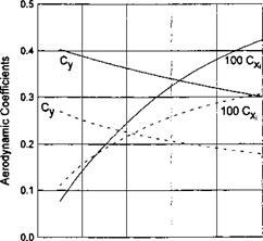
In most of this book, the modelling of the extreme ground effect implies that the ground clearance is much less than the chord and the span. This type of ground effect, associated with pronounced stagnation under the wing, will be designated as chord dominated ground effect (CDGE).[64] On the other hand, when considering the aerodynamics of a wing of large aspect ratio in the extreme ground effect on the basis of lifting line theory, it was assumed that the chord is much less than the ground clearance, the latter being much smaller than the span. In this case, we can introduce the notion of a span dominated ground effect (SDGE). Although both of these effects imply an increase in the lift-to drag ratio at smaller ground clearances, it can be shown that they have somewhat different natures. To distinguish this difference, compare the behavior of the lift and the induced drag coefficients of a wing of large aspect ratio versus the ground clearance within the previously mentioned models. In the calculated examples, the relative span and angle of pitch of the wing were l = 8 and в = 0.05, respectively. In the CDGE, calculations of of lift and the induced drag coefficients were made for cases of rectangular and (optimal) semielliptic flat wings by using formulas (3.65), (3.67), (3.78), and (3.80). The aerodynamic coefficients, corresponding to the SDGE, were determined by formulas (10.27), (10.29), (10.32), and (10.35), corresponding to rectangular and (optimal) parabolic planforms.[65]
Figure 10.2 shows that for a fixed pitch angle with a decrease in the relative ground clearance (based on the chord), the CDGE model responds by an increase of both the lift and the induced drag coefficients. As seen from formulas (3.65), (3.67), (3.78), and (3.80), both coefficients within the CDGE model are inversely proportional to the ground clearance. Note that Standingford and Tuck[101] came to the same conclusion in their accurate numerical analysis of the aerodynamics of lifting surfaces for small ratios of the ground clearance to the chord.
As seen from Fig. 10.3, the behavior of lift and induced drag coefficients versus the relative ground clearance (based on span) within the SDGE model is different. In this case for a fixed pitch angle we can observe a decrease in the induced drag coefficient as the wing flies closer to the ground. The lift coefficient increases with a decrease in the ground clearance although somewhat more slowly than in the CDGE model.[66]
![]()
 |
|
 |
|
|
|
|
|
![]()
|
In these equations 2(z) stand for the distributions of the loading in the direction of the span of the front and rear wings of the tandem, C(z) represents the form of the chord distributions, and 0 1,2(2) are the distributions of the pitch angle along the span of the wings.
It can be seen from observation of the right-hand side of equation (10.36) that in the extreme ground effect, the downwash induced by the rear wing upon the front wing is negligible. At the same time, the front wing affects the aerodynamics of the rear wing, see equation (10.37). The system admits closed form solutions.
Suppose that both wings are rectangular, C(z) = 1, and flat 0i(0) = 01,02(0) — 02* Then, the first equation of the system (10.36)-(10.37) can be integrated to yield
„ , . 27Г01 /coshpz І A I l. л
^ = “T~( coshp _1)’ P = 2ЇтК = V 2nhi ^°’ ^
Substituting solution for Г (z) in the second equation of the system (10.36)- (10.37), we obtain the following nonhomogeneous ordinary differential equation for function /2(2:):
^… ~P2 r2(z) = p + gcoshpz, (10.39)
where p = 02//ii, q = 2Qi/h coshp. Integrating (10.39) and using the requirement that the loading should vanish at the wing tips Г2(± 1) = 0, we obtain the following solution for r2(z):
 |
Using expressions (10.38) and (10.40) for the loading along the front and rear wings, we can readily obtain both the lift and the induced drag coefficients for the above case of a rectangular planform of lifting elements of the tandem.
However, in what follows, the accent will be on a parabolic loading distribution for which each of the wings and the tandem as a whole have minimal induced drag for a given lift. Writing the circulations and the planform equations of both lifting lines as A,2(2) = Г0і 2(z2 — 1 ),C1>2(^) = C(z) = k( 1 — z2),k = 3/2 and substituting these expressions into equations (10.36) and (10.37), we obtain the following simple system of algebraic equations with respect to the amplitudes of the loading distributions:
wherefrom
The lift coefficients of each wing and the overall lift coefficient of the tandem C* are obtained in the form
![]() 4/.Г10 8ir9i
4/.Г10 8ir9i
~ 3 = 3(1 + 4nh/l)’
4ІГ20 _8n(92-3hiCyi/l) З “ З 1 + 4wh/l
cyt = cyi + СУ2.
In the latter coefficient, the reference area used was half that of the tandem. For optimal wing loading, the downwash on both lifting lines is uniform along the span:
Q? wi — 2/q. Ao, t^w2 — 2/11A20 H – 4/ii-Ao* (10.46)
Consequently, the induced drag coefficients for the front and rear wings can be found in the form
![]() The induced drag of the tandem as a whole[67] will be
The induced drag of the tandem as a whole[67] will be
Cx = CX1 + CX2 = ~2[(Су! + 2СУіСУ2 + Cy2) = + СУ2)2. (10.48)
It is worthwhile to remember here that an optimal tandem in an unbounded fluid (h = oo) has the following relationship between the lift and the induced drag coefficients of its elements:
CXl + CX2 — (Cyi + Cy2)2. (10.49)
10.4.1 A Single Lifting Line in the Extreme Ground Effect
The following example illustrates the application of the same technique to the integrodifferential equation of the lifting line in the ground effect. Assuming for simplicity that the longitudinal curvature of the wing’s sections is zero, we can write the lifting line equation in the presence of the ground in the form2
where r(z) is the distribution of the circulation of the lifting line spanwise, C(z) and 6(z) are spanwise distributions of the local chord and angle of pitch,[61] l is the relative span (span to chord ratio), and h = h/l is the height to span ratio. The planform function C(z) is normalized so that
і
C(z)dz = l. (10.25)
Exploring the limit h —» 0 for the flow around a lifting line near the ground, note that using the concept of a lifting line implies that the chord of the wing is much less than the ground clearance and the latter is much less than the wing span.
Thus, the limiting result will be different from that, obtained in the large aspect ratio limit from our previous analysis in Section 3. In the latter case, the distance from the ground is much smaller than the chord, and the chord is much smaller than the span.
|
d2r(z)-| dz2 |
Quadruplicating the integral part of equation (10.24), we obtain the following ordinary differential equation of the second order:
Equation (10.26) should be solved with boundary conditions of zero loading at the tips of the wing, i. e, Г(± 1) = 0. Suppose that 6(z) = в is constant, i. e., the wing is flat.
Consider first the case of a constant chord C(z) = 1 (rectangular wing), for which the resulting expressions for the distribution of the circulation along the lifting line and lift coefflcient can be obtained as
^-«(1-^). (Ю.27)
Recalling that the induced downwash in the extreme ground effect is proportional to the second derivative of the circulation with respect to the spanwise coordinate z, i. e.,
oii(z) = (10.28)
we can derive the induced drag coefficient for a rectangular wing of large aspect ratio in the extreme ground effect in the form
![]() 7t02 sinh 2p — 2p p cosh2p + l
7t02 sinh 2p — 2p p cosh2p + l
As in Prandtl’s classical lifting line theory, the induced drag coefficient can be shown to be proportional to the square of the lift coefficient. We can write
![]() C2 Aeff 4(cosh2p + 1 )(p — tanhp)2
C2 Aeff 4(cosh2p + 1 )(p — tanhp)2
тгХр ’ ^ A A p (sinh 2p — 2p)
Examining equation (10.28), we can conclude that in the extreme ground effect, the optimal[62] spanwise distribution of loading for a wing of a large aspect ratio is parabolic rather than elliptic, as in the unbounded fluid case. As follows from (10.26), for a flat untwisted wing, the spanwise chord distribution securing a parabolic loading distribution is also parabolic. Substituting C(z) = к (1 — z2) (where from normalization condition (10.25), к = 3/2, A = 3Z/2), and r(z) = ro(z2 — 1) the equation (10.26) we obtain the following formula for Г0:
![]() = 2пв 0 /(1 4- 4тгhi/l) ‘
= 2пв 0 /(1 4- 4тгhi/l) ‘
To obtain the lift coefficient based on the chord, we have to apply the following formula: л « д
Су = Г01 (1 – z2)dz = ———————– 7. (10.32)
•’-і ЗМ+47г/іі/Л
The downwash corresponding to parabolic spanwise loading is constant along the lifting line. Simple calculation shows that
![]() . . . d2Г, . rtl _ Shine
. . . d2Г, . rtl _ Shine
",W = -‘‘l d? W = ~2кЛ = ~ 1(1+ 4nVO’
|
3 21 y or, rewriting (10.34) in the Prandtl’s format,[63] Aeff 4 |
The induced drag coefficient of the optimal lifting line is calculated as the lift coefficient times the induced drag, i. e.,
 |
These results show that in the limiting flow problem of a lifting line in the extreme ground effect, the effective aspect ratio is inversely proportional to the ground clearance related to the span. Figure 10.1 presents the inverse efficiency factor 1 /fi versus the relative ground clearance (based on the span) for a single wing with rectangular and parabolic plan – forms of the same relative span l = 5, operating in the extreme ground effect. Figure 10.1 was obtained by using formulas (10.30) and (10.35).
The technique of quadruplication demonstrated above can also be applied to a wing of finite aspect ratio. For example, for a flat wing of small aspect ratio, the integral formulation leads to the equation
where hx = h/X, X is the aspect ratio (/i«A« 1), and r(z) is the circulation of the velocity. The kernel of equation (10.20) has the same structure as that of (10.2). Therefore, the approach considered earlier is applicable here, too. Replacing for hx ->• 0 the integral operator by a corresponding differential one
![]()
![]()
![]() (10.21)
(10.21)
we obtain the equation
d[60]r _ в dz2 2 h
![]() Integrating (10.22) and imposing the condition of zero loading at the tips of the wing, finally, we obtain the following expression for the lift coefficient of a small-aspect-ratio wing:
Integrating (10.22) and imposing the condition of zero loading at the tips of the wing, finally, we obtain the following expression for the lift coefficient of a small-aspect-ratio wing:
![]() _ ex _ ex2
_ ex _ ex2
y 6h 6 h ’
which is identical to formula (3.69), obtained from the boundary problem formulation.
|
= /(*), |
Note that the quadruplication procedure can be applied in all cases when the kernel of the integral equation has a form similar to (10.2). For a foil with a jet flap near the ground, the corresponding integral equation can be written as (see Menshikov [165])
|
/(*) |
where
7 is the strength of the vorticity that replaces the foil and the jet; dy^/dx is the unknown distribution of slope of the jet. The vorticity (pressure difference) on the jet is assumed proportional to the jet momentum coefficient, and the curvature of the jet
1 1 d2?v-
= = x <0. (10.13)
In these relationships, y-,y” represent the local slope and the curvature of the jet and Cj is the jet momentum coeffcicient. Quadruplicating the integral operator, we obtain the following differential equations for the vorticity distributions on the foil and the jet, as well as for the jet camber line:
hp – = 0, 0 < x < 1, (Ю.14)
ax
= = x <0. (Ю.15)
dx 2 dx3 dx
Because the jet is blown from a slot at the trailing edge at a small angle r with
p – (0) = r, p(-oo)=0. (10.16)
dx dx
Accounting for (10.16), it is easy to derive the solution in the form
 (10.17)
(10.18)
The corresponding lowest order lift coefficient is given by
 (10.19)
This expression is identical to that obtained within the boundary problem formulation for a jet-flapped wing in the ground effect; see formula (6.123).
For the two-dimensional steady motion of a slightly curved foil near a flat ground plane, the corresponding singular integral equation has the form
й”рі 7«№-С, лЖ = -|г. (10.1)
where y(x) is the strength of vorticity that replaces the foil in the mathematical model, and dys/dx is a function that represents the slope of the foil camber line with respect to the horizontal axis;
IC(x-Z, h) = – (a. _ ^2 + 4/l2 = ^ _£)[(* _ £)2 + 4Л.2j (10-[59])
is the kernel of the integral equation. The first (singular) term of the kernel represents the contribution to the downwash from the foil-bound vorticity, whereas the second (regular) term accounts for the contribution of the down- wash from the vorticity of the foil mirror image. Abbreviation “v. p.” implies that the integral is understood in the sense of the Cauchy principal value.
We set the ground clearance h to zero and expand the kernel of the equation in h. It can be seen that in the course of a straightforward expansion, the kernel would vanish to the lowest order. The second – and higher-order terms would contain divergent integrals. The principal difficulty in constructing this expansion is that parameter h is not always small compared to (x – £). To single out the subdomain x -£ = 0(h), we split the integral on the left-hand side of equation (10.1) into three integrals:
 1 =
1 =
where a small parameter r? is chosen so that h – C >) -C 1- It can be shown that contributions Ii and I3 are of the order О(h2), whereas the integral I2 = 0(h). In what follows, only the middle integral I2 will be retained, and Ii and I3 will be neglected.
 For I2, the variable of integration varies in the range of x – r? <£< x + rj. We introduce a new stretched variable £ = (£ — x)/h, which has the order of 0(1). Then, _ _
![]() (10.4)
(10.4)
Outside of the small vicinities of the edges (x = 0 and x — 1), the vortex density 7 can be expanded into a Taylor series
7(x + h£) = 7(x) + h£-y'(x) + – h2|27,,(x) + 0(/i3). (10.5)
Substituting this expansion in (10.5) gives
![]() I2 = —4 h 7 ‘(x) arctan – j – + 0(h2).
I2 = —4 h 7 ‘(x) arctan – j – + 0(h2).
Recalling that both h and T] should be small quantities with h = 0(1]), we can derive the following lowest order representation of the integral equation (10.1) for /1 —> 0:
*v<.>M
Thus, it has been shown that for very small relative ground clearances the integral equation for a foil-in-ground effect degenerates into a simple ordinary differential equation of the first order (10.7).
Recalling the relationship between the vortex density and the perturbation velocity potential tp,
d(p_ d(f+
![]() ^ dx dx ’
^ dx dx ’
and assuming domination of the channel flow velocity potential, i. e., —
0(h(p~), it is easy to identify equation (10.7) with the equation (3.32), obtained by the matched asymptotics technique within the boundary problem formulation. The equivalence (to the lowest order) of boundary conditions for the aforementioned equations (10.7) and (3.33-3.34) follows from simple physical reasoning, namely,
• the circulation of the velocity Г(х) = f* 7(£)d£ should be zero at the leading edge, i. e., the potential at the leading edge should be continuous:
![]()
Г(1) = М1)-^+(1)*М1) = 0;
As mentioned in the Introduction, asymptotic analysis can be applied directly to the integral equation of the lifting surface in the ground effect. Essentially, in the extreme ground effect, we study the limiting process, when the distance between two double (vortex) layers, representing the wing and its mirror image, becomes vanishingly small. In the limit, the two double layers merge into a quadruple layer so that the procedure can be characterised as quadruplication.[58] The main result of quadruplication is the confluence (for h —> 0) of the integral equation of the wing-in-ground effect into a differential equation (ordinary for two-dimensional flow, and in partial derivatives for three-dimensional flow). The resulting differential equation can be shown to be identical to that, obtained in the course of solving the corresponding boundary problem by the method of matched asymptotic expansions. The quadruplication approach in the aerodynamics of wings in the ground effect was first introduced by Panchenkov [64]. In what follows, all derivations will be based on a different scheme of quadruplication proposed in [66].