Our heavyweight helicopter equal in the world does not have
In Rostov started production of the most load-lifting rotary-wing car The Russian holding «Helicopt[...]

Everything about aircrafts and helicopters. News and events in aviation worldwide. Civil, transportation, military helicopters and airplanes.

Everything about aircrafts and helicopters. News and events in aviation worldwide. Civil, transportation, military helicopters and airplanes.

Everything about aircrafts and helicopters. News and events in aviation worldwide. Civil, transportation, military helicopters and airplanes.

Everything about aircrafts and helicopters. News and events in aviation worldwide. Civil, transportation, military helicopters and airplanes.


The economic efficiency of wing-in-ground-effect vehicles is directly related to the lift-to-drag ratio, which can be viewed as one of the principal design parameters. In what follows, some estimates of the lift-to-drag ratio of a lifting system in close proximity to the ground will be discussed on the basis of the simple Prandtl’s formula and the relevant results of the asymptotic theory set forth herein.
First of all, we write the induced drag coefficient of a lifting surface in the conventional form, introduced by Prandtl,
![]() = £L = £L,
= £L = £L,
7ГЛfl 7ГАЄ ’
where the function /і(/і, A) characterizes the influence of the ground and the wing aspect ratio upon the induced drag coefficient of a wing for a fixed magnitude of the lift coefficient. The quantity Ae = (i can be interpreted as an effective aspect ratio. As follows from the results of paragraph 3.4, the coefficient /і of a rectangular wing with a flat lower surface in the extreme ground effect can be calculated from the formula
|
A-*0, |
32 tanh^n tanh(gn/2)i2 /^tanh2<
qn — д (2n + 1). (9.30)
It follows from (9.29) and (9.30) that for h 0 and Cy = const., the magnitude of the induced drag coefficient diminishes proportionally to h as the wing approaches the ground. Hence, it is clear that for a lifting system operating near the ground, its effective aspect ratio depends, at least, upon one specific new parameter, the relative ground clearance.
From a practical viewpoint it is convenient to have at hand some simple formulas for evaluating the lift-to-drag ratio К == CyjCx as a function of Cy for the analysis of the existing margins for enhancing the maximum magnitude of Kmax or К for a given Cy.
Taking into account (9.29), we can write the expression for the aerodynamic fineness (lift-to-drag ratio) in the form
![]()
|
||
|
||
![]()
where CXQ is the viscous drag coefficient.
Similarly to the unbounded flow case, we can augment the lift-to-drag ratio of the lifting system by
• increasing the aspect ratio
• decreasing the induced drag by securing optimal spanwise distribution of the circulation by choosing an appropriate planform of the wing, as well as the distribution of the angle of attack (pitch) in the lateral direction;
• realizing the leading edge suction force; and
• reducing the viscous drag of the lifting system.
In addition, specific features of ground effect aerodynamics indicate that the magnitude of the lift-to-drag ratio can be increased by bringing the wing closer to the underlying surface (decreasing the relative ground clearance h) and/or mounting endplates at the tips of a wing.
The maximum of the function К takes place at a certain optimal magnitude of the lift coefficient
 (9.32)
and the corresponding magnitude of the maximum lift-to-drag ratio can be found by substituting (9.32) in (9.31):
|
|
|
|
|
|
Whereas the lift-to-drag ratio К specifies the aerodynamic efficiency of the lifting system, the product К U0 (where U0 is the design cruise speed) is closely related to its range of flight. Because the speed is inversely proportional to the square root of the lift coefficient, to find the maximum KU0, we can consider the following function:
y/Cy
СХ0+СЦ тгЛ/і*
The maximum of this function takes place at a certain magnitude of the lift coefficient, which differs from (9.32), namely,
|
|
||
|
|||
|
|||
The magnitude of the lift-to-drag ratio, corresponding to the maximum range, is
1 ЗтгХц
We can draw some practical conclusions from the preceding results. First of all, the ratio of speeds, corresponding to the maximum lift-to-drag ratios for the ground proximity and an unbounded fluid is given by the expression
![]() &
&
which shows that, the more one gains in the lift-to-drag ratio by flying closer to the ground, the less the cruise speed of the vehicle. Second, going for a larger range entails a certain loss in the lift-to-drag ratio, compared to its maximum possible magnitude. This loss can be determined (in relative terms) by dividing expression (9.35) by expression (9.33):
It is interesting to evaluate the reserves of enhancement of the maximum lift-to-drag ratio near the ground h —> 0 in comparison with the same property in unbounded flow, h -> oo. Suppose, that we compare optimal flat wings of the same relative span l. Keeping in mind that for an optimal wing operating out of the ground effect, h = oo, the loading distribution is elliptic, i. e.,
![]()
![]() (9.38)
(9.38)
we can derive from (9.14) the following expression for the coefficient /і = /i££t:
On the other hand, we can calculate the downwash w0, induced in the Tr – efftz plane by an optimal wing in unbounded fluid by using the following relationship:
Combining the two preceding expressions, we obtain the well-known Prandtl result: for an optimal wing in an unbounded fluid,
M~t = l, = (9.41)
The magnitudes of the maximum lift-to-drag ratio and the corresponding (optimal) lift coefficient for this case are
As shown in paragraph 9.2, for an optimal wing in the extreme ground effect (h —> 0), the distribution of the loading is parabolic. Therefore, the corresponding distribution of the circulation can be written as
![]() r(z) = rm(l-z2).
r(z) = rm(l-z2).
Substituting this formula in (9.4), we obtain the following expression for the factor /і = fiQpt when /і —> 0:
Now, we can derive a relationship between the downwash w0 and the parameter Гт, using formula (9.20) for the downwash behind the (straight) trailing edge of a wing in the extreme ground effect:
Finally, using the two preceding equations, we find that where h = h/l represents the distance from the trailing edge to the ground, related to the span of the wing.
Eventually, the capacity of the lifting surface without endplates to take advantage of the closeness to the ground can be evaluated with the help of the following formula:
Note that this formula was obtained by assuming that the loading is optimal both for h —> 0 and h —> oo.
The corresponding ratio of (optimal) lift coefficients in the extreme ground effect and an unbounded fluid has a similar form:
 (9.48)
Employing formulas (9.32) and (9.34), we can see that the cruise speed corresponding to the maximum range always exceeds that corresponding to the maximum lift-to-drag ratio. The ratio of these speeds is constant, and
![]()
Therefore, the expected gain in range, when flying in the extreme ground effect as compared to flying far from the ground (without accounting for the variation of the density of air) can be estimated by using the ratio

 (9.50)
To evaluate the margins connected with the realization of the suction force, it is beneficial to know the ratio of magnitudes of the maximum lift-to-drag ratio with fully realized suction force Km8iX to that with no suction force Kmax – We take example of a rectangular wing for h —» 0. If the flow near the leading edge is not separated, suction is realized, and the factor ц can be determined by equation (9.30). If there is no suction force, which may happen due to improper profiling of the leading edge, the factor fi for a wing of rectangular planform can be found in the form
 |
 |
Taking into account relationships (9.30) and (9.51), the loss in the lift-to-drag ratio when the suction force is not realized, can be assessed by the formula
For rectangular wings of small aspect ratios, it follows from expression (9.52) that
= y/2. (9.53)
-^•max
This is exactly the same result as that for unbounded flow. In Fig. 9.1, the calculated fraction Kmax/Kmax is plotted versus the aspect ratio A for h 1. In the same figure, the dashed line represents calculated data, corresponding to the motion of a rectangular wing in an unbounded fluid; see Belotserkovsky and Skripach [130].
We can deduce from the above analysis that for wings of moderate and large aspect ratios, realization of the suction force results in a larger increment of the maximum lift-to-drag ratio than in an unbounded fluid. Therefore, considerable attention should be paid to profiling the leading edge of the wing in the extreme ground effect.
5.0
![Подпись: 0 1 2 3 4 5 x б Fig. 9.1. The ratio of the maximum lift-to-drag ratio of a rectangular flat wing with suction force to that without suction force versus the aspect ratio (solid line: extreme ground effect; dashed line: out-of-ground effect [130]).](/img/3131/image1113.gif) Kmax
Kmax
77 4.5
‘Vnax
4.0
3.5
3.0
2.5
2.0
1.5
1.0
As already discussed, it is possible to improve the aerodynamic quality of lifting systems near the ground by mounting endplates on the tips of the wings. In this case, the efficiency factor /і should be replaced by /iep. Restricting consideration to the case of lower endplates, we can find the latter coefficient as
![]() /^ep(^? hep/h) — А)кер,
/^ep(^? hep/h) — А)кер,
where hep/h is the ratio of height of the endplate to the ground clearance and the factor кер = Cyep/Cy characterizes the relative augmentation of the lift coefficient due to the influence of the endplates and can be calculated by using (6.30). The maximum relative gain in the lift-to-drag ratio, resulting from the installation of lower endplates on a rectangular wing, can be evaluated by the formula[51]
![]()
![]() _______ ^ep_______
_______ ^ep_______
/l + (2 hep + в)/A where the denominator takes account of the augmentation of the wetted area of the wing due to mounting of the (lower) endplates and в is the adjusted pitch angle in radians.
Returning to Fig. 6.4, we can see that for a wing of a small aspect ratio in the presence of endplates, the gain in aerodynamic quality can be quite noticeable. For example, if the height of the lower endplates at the trailing edge constitutes 60% of the ground clearance, then, for a rectangular wing of
К
![]()
![]()

 aspect ratio Л = 0.7, flying at relative distance from the ground h = 0.07 at incidence в = 0.05, we can expect augmentation of the order of 25% of the maximum lift-to-drag ratio compared to that with no endplates.
For the optimal wing,[52] the maximum lift-to-drag ratio can be determined by the formula
= (9-56)
where /iopt is the optimal (maximal) magnitude of the coefficient (i.
To decide whether it is worthwhile to attain an optimal spanwise loading distribution, it is practical to evaluate the following ratio:
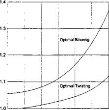
Figure 9.2a presents the fraction (9.57) versus the aspect ratio Л for an optimal distribution of the angle of pitch for a rectangular wing in the extreme ground effect. Figure 9.2b shows the relative increment of the maximum lift – to-drag ratio for a wing with optimal organization of jet ejection along the trailing edge versus the aspect ratio in comparison with uniform blowing.
It is interesting to be able to evaluate the influence of the dynamic compressibility of air upon the lift-to-drag ratio. It was shown in section 5 that for
 |
a given Mach number, incompressible flow results can be used in compressible flow but for a smaller aspect ratio A’ = A^/l – M02, smaller clearance hf = hy/І" — M02, and larger angle of pitch в’ = ву/і – M02. Using the expression for the maximum lift-to-drag ratio given by (9.33) and assuming that the viscous contribution remains the same, we can roughly estimate the relative effect of compressibility on the maximum lift-to-drag ratio for different aspect ratios and Mach numbers; see Fig. 9.3.
We can use formula (9.31) to analyze the influence of different factors upon the lift-to-drag ratio of a flying wing of rectangular planform with end – plates on the basis of the one-dimensional nonlinear flow model developed in section 4. Following Rozhdestvensky [63] and Kubo [162], some results are represented herein of calculations illustrating the behavior of the lift-to – drag ratio of the previously mentioned simple configuration versus the design parameters. To evaluate the aerodynamic efficiency of a wing, a simplified calculation of the viscous contribution to drag is used, based on the concept of an equivalent flat plate, see Voitkunsky et al. [163] or Raymer [164]. Hence, it is assumed that a lifting system has viscous (friction) drag identical to that of a flat plate that has the same wetted area, length,[53] and speed. Correspondingly, the friction drag coefficient for fully developed turbulent flow is determined as
~ 0.455
f ~ (log Де)2 58’ (9-58)
where Re = UqCq/v is the Reynolds number based on the root chord and cruise speed. The area of the wetted surface of the flying wing configuration,
related to the square of the root chord Sw, is determined by the formula
Sw = 2A + SWep, (9.59)
where SWep is the wetted surface of (two) endplates of given configuration, related to the square of the chord length.
The latter quantity can be defined as
^ер = 4 /* hep(x)dx, (9.60)
Jo
where hep(x) is a given chordwise distribution of the height of the endplate as a fraction of the chord of the wing.
In the particular case of a flat wing and uniform distribution of the gap between the endplates and the ground, formula (9.60) yields the following result:
Sw = 2(A + 2/iep + 0), (9.61)
where hep represents the relative height of the endplate at the trailing edge.
Accounting for the fact that in the calculation of the lift and the induced drag coefficients, the reference area was that of the wing‘s planform, we can obtain the resulting expression for determination of the viscous drag coefficient[54] based on the wing reference area:
CX0 = Cf(2 + ^). (9.62)
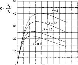
Figures 9.4-9.7 are graphs of the lift-to-drag ratio versus the lift coefficient. Figure 9.4 illustrates the influence of the relative ground clearance and the design lift coefficient upon the aerodynamic efficiency of a flat thin wing of rectangular planform with endplates. For each magnitude the design lift coefficient, the gap between the tips of the endplates and the ground is uniform chordwise.
It can be seen from the graph that, when a wing operates in the extreme ground effect, a decrease in ground clearance results in a considerable increase in the lift-to-drag ratio. At the same time, the optimal lift coefficient[55] increases. Figure 9.5 demonstrates the same tendencies for the influence of the gap under the endplates upon the aerodynamic efficiency of the configuration. The dashed lines correspond to the case when the leakage of the flow from under the endplates occurs with contraction; see the considerations on the effective gap in paragraph 4.3 and the solution of the local problem for contracted leaking flow under the endplate (or flap) in paragraph 8.1.3 of section 8.
 |
It is easy to conclude from Fig. 9.5 that a decrease in the gap under the endplates may result in considerable augmentation of the lift-to-drag ratio. Simultaneously, the optimum lift coefficient increases. In addition, realization
|
7 Fig. 9.6. The lift-to-drag ratio of a rectangular wing with endplates in the extreme ground effect versus the design lift coefficient for different aspect ratios (flat plate, gap uniform spanwise, h = 0.1, Re = 1.34 x 10⁹, Л = 1). |
of contraction of the flow escaping from underneath the vehicle may lead to significant gains in the aerodynamic efficiency.[56] The influence of the aspect ratio upon the lift-to drag ratio for a fixed gap under the tips of the endplates is shown in Fig. 9.6. This figure shows that the augmentation of the aspect ratio leads to an increase in the aerodynamic efficiency and increases optimun lift coefficient.
The dependence on the Reynolds number of both the lift-to-drag ratio and the magnitude of the optimum lift coefficient is illustrated in Fig. 9.7 and gives rise to an obvious conclusion: the larger the Reynolds number the larger the aerodynamic efficiency, and the smaller the optimum lift coefficient. The latter circumstance together with observations related to the influence of other design parameters, as discussed above, shows that the way to increase the cruise speed of the vehicle,[57] when flying close to the ground, consists of increasing the design Reynolds number. Other factors, leading to the enhancement of the lift-to-drag ratio, such as increase in the aspect ratio, decrease in the ground clearance and/or height of the endplates, result in a diminution of cruise speed for a given magnitude of wing loading.
Figure 9.8, plotted on the basis of the one-dimensional nonlinear theory of section 4, confirms the result discussed previously in this paragraph, namely, if suction force is not realized (e. g., due to stall) the efficiency may drop considerably.
 |
cy
Fig. 9.8. The lift-to-drag ratio of a rectangular wing with endplates in the extreme ground effect versus the design lift coefficient for realization of the suction force and no suction force (flat plate, gap uniform spanwise, h = 0.08, Re = 6 x 10⁸, A = 0.8, $ep/h = 0.25).
9.1 Optimal Wing-in-Ground Effect
The theory of a wing in the extreme ground effect, as developed herein, enables us to formulate a number of extremal problems, which are of both theoretical and practical interest.
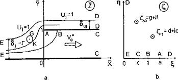
We consider the conditions of the minimality of the induced drag of a lifting system in the extreme ground effect in Munk’s sense [159]. We assume that a thin vortex wake extending behind the trailing edge represents a cylindrical surface with a generatrix parallel to an unperturbed underlying boundary. This assumption permits us to assume that, at a sufficient distance downstream from the lifting system, the flow is close to two-dimensional in the plane normal to the direction of motion (a Trefftz plane). It is known that the induced drag coefficient can be expressed by the integral over the whole Trefftz plane St of the kinetic energy of a fluid per unit length in the direction of motion, see Ashley and Landahl [161] and Barrows and Widnall [160]:
CXi =Y2Л (9.1)
In formula (9.1), all quantities were rendered nondimensional by using some characteristic (cruise) speed U0 and the length of the root chord C0. The differential d5x represents a differentially small area element in the Trefftz plane, related to the square of the root chord. Quantities Л and l represent, respectively, the aspect ratio and the relative span of the lifting surface, (p is the velocity potential of the perturbed motion of the fluid.
Using Green’s theorem, we can transform integral (9.1) into a contour integral:
where Cjj is the contour in the Trefftz plane that incorporates a contour Cl that encloses the wake and a contour C2 that coincides with the line of intersection of the ground and the Trefftz plane. Taking into account the tangency condition on the ground, we can transform (9.2) into an alternative form
K. V. Rozhdestvensky, Aerodynamics of a Lifting System in Extreme Ground Effect © Springer-Verlag Berlin Heidelberg 2000
C-‘ – P І Vtn a = P il’ (9’3)
where C is the contour of the wake passed in one direction. Within the assumptions of linear theory, the expression for the lift coefficient for a wing of small aspect ratio with a curvilinear lateral axis can be written in the form
C, = ^ /i<I’)c°s<n,!’,dS = f Д(:aT~llr)cos("’!/,’:ls
2Л r 2X f
= JJ-V+ ~<P-)<x>s(n, y)dl = – jj J^r(l)cos(n, y)dS, (9.4)
where n is a normal to a curvilinear cut that represents the wake in the Trefftz plane. To determine the conditions of the minimum of the induced drag for a given magnitude of the lift coefficient, we find a minimum of the function
V = CXi-*Cy, (9.5)
where A* is the variational Lagrange multiplier. Then, in accordance with variational calculus, a variation of the function V must be equal to zero, that is,
2A f
SCXi = -p VtpV6<pdST. (9.6)
St
Turning to contour integration with the help of Green’s formula, we obtain
SC“ = ж fSrllnil’ <9’7>
c
|
— A* cos(n, y) |
Taking into account (9.7), we obtain
For an arbitrary variation of the equality (9.8) is possible only if
= A*cos(n, y). (9.9)
It can be seen from (9.9) that A* represents the vertical downwash w0 in the middle of the wake. Thus, the expression (9.9) can be rewritten as
dip
— =vn = w0 cos(n, г/), (9.10)
which corresponds to the following theorem (Munk [159]): The induced drag of a wing is minimum if the normal component of the induced
downwash at each point is proportional to the angle of inclination of the lifting element at this point. Taking into account (9.10), the expressions for the coefficients of the lift and the induced drag of an optimal wing take the form
|
– 12 |
a II "3 9-І £ cs |cs |
rl/2 Г(г) dz, – it 2 |
(9.11) |
|
2A / |
’ 2A |
fl/2 x x |
(9.12) |
|
Cy = lJ j |
r(l)cos(n, y)dl = – p |
r(z)dz. J—1/2 |
Using Prandtl’s representation of the relationship between the lift and the induced drag coefficients, we obtain
 where
where
The product A/і = Ae is called the effective aspect ratio of the wing and can be used as a measure of the aerodynamic efficiency of the lifting system.
|
h*(x, z), |
|
dh* Их’ |
|
dh* „ -5- < 1, dz |
Now, we can find the form of the optimality condition for a wing in close proximity to the ground. Recalling that in the asymptotic theory, discussed herein, both the gap and its chordwise derivatives are assumed small
|
h*(0,z) |
and by using the formula for the determination of induced downwash at points of the wake in steady motion, we obtain the following form of the optimality condition for a laterally curvilinear wing in the extreme ground effect:
where h*(0, z) is the distribution of the distances of points of the trailing edge from the ground and Г = T(z) is the distribution of the circulation along the trailing edge of the wing. Integrating (9.16) taking into account that the loading must vanish at the tips of the wing,
г-=”"/-‘/жЛ2′ (917)
The constant C was determined by using the requirement that the circulation should vanish at the extremities of the wake (wing).
If the lateral curvature of the wing’s surface is negligible, Munk’s theorem is reduced to the requirement that the downwash should be constant span – wise. In the limit of vanishing clearances h and taking into account (9.10), the requirement of optimality of a wing in the extreme ground effect can be reduced to
Integrating (9.19) and taking into account that the tip loading should be equal to zero, i. e., ^(0, ±A/2) = 0, we obtain
iph = ^K{z2~x2)- (9-20)
Thus, the optimal wing in the extreme ground effect has a parabolic spanwise distribution of circulation. This conclusion reveals a distinction of the aerodynamics of the extreme ground effect from that in an unbounded fluid, where the optimal wing has an elliptic loading distribution spanwise. It is also compatible with the results of de Haller [134], who obtained an exact solution for an optimal wing in the Trefftz plane in terms of an infinite series of elliptic functions and demonstrated by calculations that, when the clearances diminish from infinity to zero, the optimal loading distribution changes from elliptic to parabolic. Returning to the solutions derived in paragraph 3.5, we can see that a semielliptic wing is optimal for any aspect ratio and that a flat wing of small aspect ratio in the extreme ground effect is optimal independently of its planform. Similar conclusions follow from the theory of a lifting line(s) in the extreme ground effect, set forth in section 10, where parabolic spanwise loading also furnishes the minimal induced drag for a given lift.
Using the results of linear theory, stated in paragraph 3.4, we can study the requirements for the optimality of a rectangular wing of an arbitrary aspect ratio. In a sufficiently general case, the spanwise distribution of the circulation at the trailing edge of a rectangular wing for h —> 0 can be written as follows:
oo ^
Vli (0; z) — ^2 an cosqnz, qn = -(2n + l). (9.21)
71=0
Comparing expressions (9.20) and (9.21), we can determine the coefficients subject to the optimality condition:
Due to the fact that the coefficients an reflect the specifics of a concrete problem, condition (9.22) enables us to find the optimal spanwise distribution of the different parameters, such as aerodynamic twisting, jet flap momentum distribution, etc.
For example, we can find such a distribution of the angle of pitch for which a rectangular wing of arbitrary aspect ratio has a minimum induced drag. From the solution of the corresponding flow problem for an arbitrary spanwise distribution of the angle of pitch 0(z) = 9o0(z), presented in paragraph 3.4, it follows that at a point on the trailing edge
У’іДО, z) = –Г "T tanh qn tanh cos qnz, (9.23)
h n=o Яп 1
where
2 /^/2
0n = – r 0(z) cos qnz dz.
л J-X/2
The coefficients вп in accordance with (9.22) can be derived from the equation
Consequently,
Therefrom, the optimal spanwise distribution of 9{z) for a rectangular wing (aerodynamic twist) of arbitrary aspect ratio A is described by the following equation:
<a ( – 4u>° ( l)n cos Qnz
~ °pt 2 A0O ^ qn tanh qn tanh(g„/2)’
For a wing of small aspect ratio A -> 0 (qn ->• oo), this expression yields
and therefore, no aerodynamic twisting is required for the optimization of a rectangular wing of small aspect ratio.
For a wing of large aspect ratio Л oo (qn 0),
It follows from (9.25) that an optimal rectangular wing of large aspect ratio in the extreme ground effect should have a parabolic distribution of the angle of pitch. It can be shown that a noticeable gain in the
lift-to-drag ratio can be achieved only for wings of sufficiently large aspect ratios.
In another example, we find the optimal distribution of the jet momentum along the trailing edge of a rectangular wing with a jet flap. Based on the results obtained in paragraph 6.2 of section 6, at points of the trailing edge of a jet-flapped rectangular wing-in-ground effect,
 an = —r – [ Jc^z) cos qnzdz. л J-A/2 v
 4w0(—1)"
Vhql ’ from which
4u;0(—l)ra
a” Arqltanh qn ’
so that the optimal distribution of the jet velocity distribution along the trailing edge is given by the following expression:
Setting the aspect ratio to infinity, we derive a parabolic distribution of the jet velocity in the form
For a wing of small aspect ratio,
fc; _ 4w0 (-l)ncos qnz _ 4w0
V 2 – At ^ ql ~ At
Bearing in mind that the derivative of S(z) can be summed up in a closed form (see Gradshtein and Ryzhik[147], p. 52),
and integrating (9.28), we can express the right-hand side of (9.27) by the Lobachevsky function L(u) (see Gradshtein and Ryzhik [147]),
This formula describes an optimal law of ejection of air along the trailing edge of a rectangular wing with a jet flap.
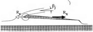
The PAR model based on a reentrant jet scheme does not account for the suction force at the leading edge. At the same time experiments show that the incoming jet has a tendency of enveloping a rounded leading edge. For a relatively thin jet spilling over the edge, this phenomenon can be identified with the Coanda effect. Gallington [155] and Krause et al. [156] remark that PAR theory,[47] on average, underestimates the efficiency of power augmentation predicted by experiments, because it completely neglects the Coanda effect. In this connection, an attempt can be made to develop a PAR flow scheme which would incorporate a manifestation of the Coanda effect. One model of this type is proposed herein for further discussion and evaluation. The main idea of this model is that, whereas the angle /3j of the overspilling jet with respect to the x axis is governed by the momentum law, the detachment of the jet takes place tangentially to a rounded leading edge at a certain point with an abscissa Xsep (see Fig. 8.17). In this case, the suction force is realized only on the “wetted” part of the surface of the leading edge.
To calculate the suction force acting upon the “wetted” part of the rounded leading edge, we consider a local flow in the immediate vicinity of the leading edge with a rounded nose. It can be shown that for a wing with
|
|
|
Fig. 8.17. The definition of a PAR flow model with a partial realization of suction force (the Coanda effect). |
analytical cross sections at 2 = const,[48] the rounded leading edge at distances of the order of its radius of curvature pe is approximated by a semi-infinite parabolic cylinder.
As derived in Rozhdestvensky [44], the pressure coefficient рг on an osculating parabola has the following quasi-steady form:[49]
(8Л64)
where parameters U and U2 characterize the velocities of the local incoming and the circulatory flows around the rounded leading edge, thus determining the position of the stagnation point. These parameters have to be determined by matching with an appropriate outer flow field; X = xe/pe is the stretched local abscissa and xe is the unstretched local abscissa.
It should be noted that for an analytical wing section, pe = 0(6%), where 5t is relative thickness of the wing section. On the other hand, within the assumptions of the theory of the extreme ground effect adopted in this book, the relative thickness of a wing section is of the order of the relative ground clearance 0(h); see (2.1). Therefore, for analytical foils, the radius of curvature is assumed to be of the order of 0(h2).
We calculate first the suction force coefficient when the flow past the osculating parabola is not separated. Representing the pressure coefficient on the surface of the wing section near the rounded leading edge as
![]() XU% 2Ui U2/X Щ
XU% 2Ui U2/X Щ
X + 1/2T X + 1/2 X + 1/2’
we can observe that the two first terms of (8.165) are associated with symmetrical flow around the parabola and therefore make no contribution to the suction force. The third and the fourth terms are due to the circulatory flow around the edge.
Hence these terms have to be taken into account when calculating the suction force. It is easy to see that the third term of (8.165) changes sign, when passing from a point on the upper branch of the parabola to a mirror reflection of this point on the lower branch of the parabola. This means that the sum of the longitudinal pressure forces due to the third term, acting upon parabola, should be equal to zero. In connection with these conclusions, the calculation of the suction force can be reduced to the integration of just the fourth term of (8.165), i. e.,
where ds is an arc element. Taking into account the equation of a parabola У = ±ріел/2Х, we obtain
![]() 4C/|pie arctan v2X — ЪкЩрхе,
4C/|pie arctan v2X — ЪкЩрхе,
where Y = y/pe. To find U2 we match the asymptotic expansions for the velocity on the foil in three characteristic regions: the immediate vicinity
of the leading edge of the order of pie = 0(/i2), the larger vicinity De of the order of 0(h) of the leading edge, and the channel flow D under the wing. In Dh2 expression for the velocity on a parabola, corresponding to (8.165), is
In De by using the formula (2.39) of Section 2, the flow velocity of the relative motion in points on the leading edge can be written as
^ = _[/(i) + /loa1^e-+O(h20), (8.169)
where (pae is determined by formula (2.43). Matching (8.169) with the channel flow velocity v(x, t) and accounting for the asymptotics of (2.47), leads to the following expression for a\
ai = h*(l, t)[U(t)+v(l, t). (8.170)
Now, we can write the final expression for the suction force coefficient, taking into account (8.167) and (8.171), as
![]() h*{l, t)[U(t) +v(l, t) l2
h*{l, t)[U(t) +v(l, t) l2
2tt
where hi = hi(0,z, t)/h. It can be seen that the expression for the suction force coefficient, obtained by direct integration of pressure forces, acting on a parabolic leading edge, coincides with that determined by using the strength of the square root singularity of the perturbed velocity at the leading edge of an infinitely thin wing section.
Later on, it is assumed that the suction force is realized only on the “wetted” part of the osculating parabola. Then the suction force fraction ks (that is, the degree of realization of the suction force) can be calculated by direct integration of the local pressure coefficient p given by formula (8.165), along the corresponding “wetted” part of the parabolic edge. This integration leads to the following result:
ks = -(1 + – arctan ^2XsepJ, (8.173)
where ks = CsPartial/Cs is the suction force fraction, ranging from zero to unity. At the same time, the angle /3*ep is calculated with use of the equation of a parabola, i. e, Y = y/2Xsep as
Asep = arctan. ^ . (8.174)
J y/2Xsep V ‘
Comparing the last two equations, we can see that the angle of detachment of the jet from the contour of the parabola can be expressed by the suction force fraction by using the following expression:
![]() /5fep = 7Г(1 – Ks)-
/5fep = 7Г(1 – Ks)-
Thus, a PAR flow scheme can be composed of one model parameter (the suction force fraction fts)[50] and accounting for Coanda effect. To determine the PAR efficiency diagrams for this case, we can write the corresponding momentum equation as
 – Ct – – Cx – C? artial
Ct = x = 25j = 2* + – p————— ^
h 1 — cos p.
Employing the suction force fraction k8, we can rewrite the previous equation in the following way:
|
|
Supplementing this equation with expressions for the PAR efficiency if par h and the thrust recovery fraction Tr, in the simplest case of zero gap under the endplates, we obtain
![]() ^ Су, і-Щ
^ Су, і-Щ
Kpar h = —h = —=—,
m , Cx-Cs л (1 – KS)CX л (1-KS){1-Si)2
Tr = 1————- cr-1-—^— = 1————————————– 7T.———
where Ct can be calculated with help of (8.169).
We can use the relationships (8.169-8.171) that feature the parameter 1 > ks > 0 to plot PAR efficiency diagrams accounting for the Coanda effect; see Fig. 8.18.
As seen from this figure where both (reentrant jet flow and Coanda flow) types of PAR efficiency envelopes are shown simultaneously, the overall prediction accounting for the Coanda effect gives higher magnitudes of if par and somewhat higher magnitudes of the thrust recovery fraction for the same combination of and Sf. We can also see from the observation of Fig. 8.18 that for certain combinations of the thrust coefficient and the rear flap setting, the efficiency of power augmentation with the Coanda effect reaches its maximum value. As follows from (8.179), at a fixed flap setting 5f, the minimal magnitude of the thrust coefficient is attained at fcs = 0.258 and can be found from the expression
CtmIn №) = 2S{ + 0.439 (1 – Sf)2. (8.180)
 |
The corresponding thrust recovery fraction and the (maximal) PAR efficiency depend on and can be calculated by the formulas
Ct
Fig. 8.18. Comparison of PAR efficiency envelopes based on two flow models : a reentrant jet model and the Coanda flow model with partial realization of the suction force.
|
Table 8.1 PAR efficiency and thrust recovery for optimal settings of a rear flap
|
Table 8.1 presents the adjustment magnitudes of the rear flap settings and the (minimal) thrust coefficents, as well as the corresponding magnitudes of the PAR efficiency and the thrust recovery fraction.
The simple nonlinear one-dimensional theory of a rectangular wing with end – plates in the extreme ground effect, introduced in section 4, can be used together with PAR efficiency envelopes for qualitative prediction of the efficiency of power augmentation in a range of design parameters, including the adjusted pitch angle, the height of the endplates, the aspect ratio, and, the geometry of the lower surface of the wing. Simultaneously, such a mathematical model can be used as a tool for development of technical measures to enhance the performance of the vehicle both for power-augmented takeoff and cruise.
Taking into account these results, we can write the PAR efficiency and the thrust recovery fraction as
where the lift coefficient Cy and the drag coefficient Cx depend on the parameters G = 28ep/Xh = 25ep/A,[44] 9 = 6/h (6 the angle of pitch), = Sf/h, 8f the effective gap under the flap, en — єп//і, є the parameters of the form of the lower surface of the wing, Ct = Ct/h, and Cx = Cx/h. In the potential flow theory, the thrust coefficient and the width of the incoming jet are connected with each other as Ct = 2<Sj (or Ct = 2<Sj). The coefficients Cy and Cx can be determined by using the formulas of section 4, the latter without accounting for the suction force. Sets of curves corresponding to constant magnitudes of the thrust coefficient Ct and the effective gap of the flap 5f can be obtained from (8.148)-(8.149) by exclusion of Ct or respectively. The lower bound of the diagram is a straight line with the equation
(KPARh)mia = &)_ (1 – Tr). (8.150)
CX’ <5f=0
As seen from (8.150), the lower bound can be lifted if one manages to increase the lift-to-drag ratio of the wing in conditions of complete blockage of the flow under the flap (8f = 0). In the general case of a wing of finite aspect ratio, the upper bound of PAR efficiency in the scheme with a reentrant jet can be found through application of the momentum theorem and accounting for the mass conservation of incoming and escaping jets in the system. We adopt a general, though somewhat simplified, scheme of the interaction of jets due to power augmentation with the wing in the three-dimensional case, based on the PAR flow model with a reentrant jet. One should take into account that outgoing jets escape from under the rear flap and through the gaps under the tips of the endplates. Applying the momentum theorem in a projection onto the horizontal direction and rendering the resulting relationship nondimensional, we obtain
2A5j – 2A5Uj cos/?j – 2X5f – 2Iep = ACx, (8.151)
where Suj is the width of the reentrant jet,[45] and Iep is the lost momentum due to leakage through the gaps under the endplates. The momentum loss due to leakage can be determined by chordwise integration of the local momentum loss at cross sections x = const.:
і
Iep = 2 J vlp(x)6ep(x)dx (8.152)
о
or taking into account the relationship (4.51) between the velocity of the leakage vep(x) and the span-averaged velocity of the channel flow v(x) in the concrete case of a steady flow,
«ер = 1 – V2(x). (8.153)
We introduce the distribution of an effective gap under the endplates 5ep(^) = 5lpA(x), where, as earlier, <5ep is an effective gap under the endplates at the trailing edge and A{x) is a function of the order of unity that characterizes the form of this distribution. Taking into account the designation of parameter G = 25ep/h, we rewrite (8.152) as
і
/ep = hXG J [1 — v2(x)A(x) dx о
і
= hXG j p(x)A(x)dx = hGI*p, (8.154)
0
where h is the relative ground clearance, p(x) = l—v2(x) is the span-averaged pressure under the wing, and factor I* is determined by integration:
IeP= [ p{x)A(x)dx. (8.155)
Jo
In the particular case when the gap under the endplates is uniform chordwise, that is, A{x) = 1, the magnitude of Iep can be expressed in terms of the lift coefficient in the following way:
/ep = hXGCy. (8.156)
As a matter of fact, Iep represents the momentum drag and should be added to the drag coefficient Cx of the wing. Note, that in the PAR flow model, employing the scheme of a reentrant jet, the suction force is not realized.
To exclude the width of the jet escaping downstream £Uj from (8.151), we apply the requirement of mass conservation in the form
A<5j — A<SUj + A5f + 2Qep, (8.157)
where Qep is a nondimensional expression for the rate of air flow leaking through gaps under the endplates. This expression can be determined in the following way:
і
= ^ V^^)Sep(x)dx 0
l
= hGX I vW)A(x)dx=±hGQlp, (8.158)
0
Substituting (8.147) and (8.149) in (8.144), accounting for (8.150),
Setting /?j = 7Г, we obtain the equation of the upper boundary of the PAR efficiency diagram
|
c..,. = Mu. = Mt + і (c, + 2^ + 2^), Cx + 2hGI* |
|
Ct. lmm Cx + 2G(I*p + Q*ep) |
![]()
![]()
 |
||
(-^■PAR ^)max —
![]() C! L + 2C^£
C! L + 2C^£
Ct_._
where Ctmln = Ctmln/Mjmln = 5imJh, and Cx = Cx/h, and Цр and Q*p are calculated by using formulas (8.147) and (8.150).
It important to note that for fixed magnitudes of в and en characterizing the angle of pitch and the geometry of the channel between the wing and the ground, as well as for a given form of the endplate gap distribution, both the upper and lower bounds of the PAR efficiency envelopes depend on a similarity criterion G = 28ep/Xh. Both bounds of the diagram can be shown to move down with an increase in G. In its turn G increases with an increase in the relative gap under the endplates 5ep, a decrease in the aspect ratio A, and a decrease in the ground clearance h.
Figures 8.13-8.16 show some calculated results that illustrate the influence of different factors on PAR efficiency diagrams.
In particular, Fig. 8.13 presents the influence of parameter 0 (where 9 is measured in radians) for no leakage (5°p = 0). It can be seen that an increase of 9 leads to shifting of the PAR efficiency domain downward, so that for
 |
Ct
Fig. 8.13. The influence of the angle of pitch upon the PAR efficiency (zero gap under the endplates).
any given pair of magnitudes Ct, <5f, the efficiency of power augmentation diminishes.
We turn to consideration of the influence of parameter G, which plays the role of an equivalent (generalized) gap under the endplates.[46] Just for simplicity of the analysis in these calculations, it was assumed that the effective gap under the endplates is constant chord wise A(x) = 1.
It follows from Figs. 8.14, plotted for a flat plate at zero incidence and a deflected flap, that augmentation of parameter G leads to a significant reduction of the PAR efficiency (the whole diagram drops down).
It is interesting to evaluate the influence of the curvature of the lower surface of the wing for в = 0 and a different G. It is seen from the PAR efficiency envelope (see Fig. 8.15) for a curved wing that an increase in the relative curvature Sc = Sc/h results in an increase in J^par^? especially in the range of larger magnitudes of the thrust recovery fraction. Similarly to a wing without curvature a nonzero gap under the endplates leads to reduction of the efficiency of blowing for a wing with endplates.
It is not difficult to explain a decrease in the PAR efficiency for a nonzero angle of pitch в > 0 and an improvement in efficiency for a wing curved upward. As the matter of fact, within the scheme of the reentrant jet an increase in the angle of pitch results in an increase in the pressure drag. At
 |
Ct
 |
Fig. 8.14. The influence of the endplate gap similarity parameter G = 5^/Xh upon the efficiency of the PAR regime.
the same time (at least for <5f not close to unity) the relative increment of Cy due to the angle of pitch is insignificant because the flow under the wing is already deccelerated due to the deflection of the flap.
Curving of the lower surface at a zero pitch angle (0 = 0), we can gain the same increment of lift as that of a flat wing with a nonzero pitch angle. At the same time, the corresponding pressure drag becomes much smaller the because horizontal component of the pressure force acting upon rear part of the wing is canceled by the pressure force (thrust) acting upon the forward part of the wing. Practically, because the vehicle normally has a certain (design) angle of pitch adjusted for cruise conditions, it is desirable, when using power augmentation at takeoff, to generate effects analogous to the action of curvature. This can be done by forward flaps.
Figure 8.16 illustrates the influence of a forward flap upon the PAR efficiency of the wing in the extreme ground effect. In this example, the forward flap has a chord, constituting 20% of the wing’s root chord C0. Deflection of the flap was chosen to locate its leading edge tip at the level of or lower than the hinge of the rear flap. In the example under discussion, the former position is achieved for a flap deflection angle 9e = (1 — be)9/be. For example, when 9 = 2°, 9e should be not less than 8°.
 |
It follows from consideration of Fig. 8.16 that for nonzero angle of pitch and forward flap deflected downward, the efficiency of power augmentation increases for a given 9. If 9e > (1 — be)9/be, the efficiency domain shifts upward, so that the power augmentation efficiency becomes higher than that of a wing at zero incidence with a deflected rear flap. Essentially, this effect is due to the fact that, when the leading edge of the forward flap is lower
Ct
Fig. 8.16. PAR efficiency envelopes for a wing at an angle of pitch with a deflected forward flap (zero gap under the endplates).
than the hinge of the rear flap, the resulting pressure thrust reduces the total pressure drag of the wing.
At the beginning, it is worthwhile to clarify the procedure for determining PAR efficiency envelopes by using simple examples. First, we adopt the scheme of PAR flow with a reentrant jet (Fig. 8.1). We assume the potential character of the flow which enables us to use, in particular, the theory of jets in an ideal fluid [138]. We suppose additionally that the pressure on the boundaries of free jets is equal to the atmospheric pressure (zero perturbed pressure) and that the velocity is equal to f/j. We can write the PAR efficiency if par as
Kpar = (8.124)
where Cy = 2Ry/pU? S is the lift coefficient, S is the reference area of the wing, and Ct = 2T/pU? S is the thrust coefficient. Note that both coefficients are based upon the dynamic pressure head of the jet and the reference area of the wing. We introduce thrust recovery fraction TT
T — Rx Rx Cx, .
Tr = —= 1 –f = 1 – cp (8-125)
where Cx = 2Rx/pU? S is the drag coefficient. Applying horizontal projection of the momentum theorem to the surface bounded by flow cross sections at the nozzle of the PAR engine, the incoming jet (/-/), the reentrant jet (II – II) and the escaping jet (111-І 11), we deduce the relationships between the thrust (drag) forces and the width of the participating jets. For example, applying the above mentioned theorem to the flow cross sections at the nozzle and (1-І) accounting for the direction of the outward normal, we obtain
T cos#j = pU?5jC0, (8.126)
where C0 is the wing’s root chord. Hence, by using the definition for the thrust coefficient,
Ct cos<9j =25y (8.127)
It follows from (8.127) that, within the assumption of the potential flow theory, the horizontal projection of the thrust coefficient is equal to the doubled magnitude of the relative (i. e., expressed as a fraction of chord) width of the jet in front of the wing 5j.[42] Later on, for simplification of presentation, cos0j is omitted, so that Ct will be understood as the horizontal component of the same coefficient. Generally speaking, coefficients Cy and Ct depend on quite a number of factors (e. g., the flap deflection angle, the angle of pitch, the geometry of the wing, particularly on the form of its lower surface, the magnitude and distribution of the effective gaps under endplates in direction of the chord, etc.). However, for the moment, to illustrate the method of tracing PAR efficiency envelopes, an example of a wing with no lateral leakage at zero incidence 9 = 0 and with a flap set at an effective gap 5f is considered.[43] In this case, it follows from the previously derived formulas that
Cy = l-sj, (8.128)
Cx = h(l-8f)2, (8.129)
where Sf = 5f/h, and h is the ground clearance at the trailing edge. Note that for zero incidence, the lift and the ideal pressure drag acting upon the wing are due only to the deflected flap. The suction force is not accounted for in the reentrant jet model.
Taking into account (8.124), (8.125), (8.127), and (8.128), we write the PAR efficiency and the thrust recovery fraction as
![]() Cy(5f)h Cy(Sf) 1 – S2{
Cy(5f)h Cy(Sf) 1 – S2{
KpARh = – cr = ^- = ^l-‘
Cx(6uh) Cx(St, h) (1-Jf)2
Ct 25) 25)
where <5) = Sj/h.
Excluding the parameter 2Sj from (8.130) and (8.131), we obtain the relationship of the PAR efficiency to the thrust recovery fraction for given magnitudes of Sf.
On the other hand, excluding the parameter <5f from the same equations results in the expression of KpARh as a function of Tr for a given <5j. In fact, it follows from (8.131) that
![]()
St = 1 – /2<5j(l-Tr). Substituting (8.133) in (8.130),
Formulas (8.132) and (8.134) define sets of curves of constant values Sf = const, and Sj = const. Both the formulas and the corresponding diagrams show how to meet the required PAR efficiency and thrust recovery fraction magnitudes by an appropriate setting of the trailing edge gap for a given thrust coefficient or by securing the required thrust coefficient for a given trailing edge gap. Note, that for a thrust recovery fraction Tr ranging from zero to unity, the domain of variation of the PAR efficiency is bounded
both from below and from above. The lower bound can be determined from formula (8.132) for Sj 0 as
(KPARh)min = l-TT. (8.135)
As stated earlier, the equation of the upper bound of the PAR efficiency diagram can be obtained by applying the momentum theorem for a control surface, including cross sections 1-І, 11-І I and III-III. As a result,
pUf <5j C0 – pUf Suj C0 cos /?j – pUf Sf C0 = RX, (8.136)
or, in nondimensional form,
25j – 2Juj • cos/3j – 26{ = Cx, 2Jj = Ct. (8.137)
Accounting for the mass conservation condition
(8.138)
and substituting a concrete expression for Cx in the case under consideration by (8.129), we obtain the following expression:
|
(-^•PAR * ^)max — |
![]()
A certain magnitude of the reentrant jet orientation angle /?j corresponds to each pair of parameters (5j, Sf). Therefore, it is possible to find a magnitude of this angle, for which the coefficient of required thrust (or the required width of the incoming jet) would be minimal. This takes place at fy = тг, resulting in the following equation for the upper boundary of the PAR efficiency diagrams:
where
= 2^jm, n = 2ft + (1- /fl2 = 1(1 – ^f)2- (8.141)
As can be shown from (8.128) and (8.141), for the optimal blowing case, parameter 5{ is related to the thrust recovery fraction Tr in the following way:
 It follows from (8.142) that in the case under consideration, nonnegative values of Гг are reached if
![]() (8.143)
(8.143)
The maximum PAR efficiency, corresponding to optimal blowing, can be expressed by the formula
(■КРАЯ ‘ h)max = ) • (8.144)
Combining (8.142) and (8.144), we can derive a simple relationship between the efficiency of power augmentation and the thrust recovery fraction for optimal organization of blowing:
(^PAR ‘ h)max = л/2(1 ~ Tr). (8.145)
Note that for a fixed magnitude of the thrust coefficient Ct and a varying flap setting 5f, the efficiency of power augmentation varies between its minimal and maximal values, and the thrust recovery fraction ranges between its lower and upper bounds
(8.146)
On the other hand, for a fixed trailing edge setting Sf and varying thrust coefficient Ct, the thrust recovery fraction changes in the range
1 A 2
maxjo, 1 — 2^-—j < Tr < 1. (8.147)
Based on the preceding analysis, we can conclude that the realization of the optimal blowing regime associated with maximum PAR efficiency implies “tuning” of parameters <5j (or Ct) and in accordance with equation (8.141). If, for a given setting of the trailing edge gap, the incoming jet is wider than the optimal width, it spills over the leading edge. In this case, as indicated in [155], this redundant part of the jet does not participate in the PAR mechanism of lift. On the other hand, if the jet coming to the wing is thinner than required by the upper bound, the blowing may become completely ineffective owing to insufficient pressure recovery at the entrance of the channel flow. It is remarkable that theoretical analysis of the local flow around the leading edge, based on a reentrant jet scheme (see paragraph 1.1.1), shows that the corresponding solution exists if
2<5fj > 25f + + ^o)2)
the upper bound of the domain of existence of the solution, can be shown to coincide with the equation for the curve of maximum PAR efficiency. For the simple case under consideration, v* = — <Sf, hi — 1, wherefrom it can
be seen that the equality
2*jmin=25f + i(l-£-f)2
coincides with requirement (8.141). The PAR efficiency envelope for the simple case considered above (i. e., zero gaps under tips of the endplates, a flat
 |
Ct
Fig. 8.12. Envelopes of PAR efficiency based on a reentrant jet scheme.
lower foil surface and a zero pitch angle) is presented in Fig. 8.12. In some cases, for reasons of practical use of the PAR efficiency diagrams, it is convenient to trace these diagrams, using a set of constant thrust coefficients Ct = const., Sf = var. rather than a set of constant incoming jet thicknesses (<5j = const., Sf = var.).
Suggestions to utilize blowing under the main lifting wing of the wing-inground-effect vehicle for improved performance date back to early projects by Warner; see Belavin [1]. The technical development and implementation of the concept for large takeoff weight ground-effect vehicles is due to the effort of Russian engineers R. Bartini and R. Alexeyev. It is known that power augmentation by turbulent jets from upstream engines, directed under the wing, can be used either as a temporary, transitional mode of motion at takeoff and landing or permanently for cruise.
The efficiency of power augmentation (PAR) is determined by two main factors. The first of these factors is the magnitude of the required thrust of PAR engines for a given weight of the vehicle (the inverse quantity equal to the ratio of the lift Ry to the required thrust T can be characterized as the efficiency of power augmentation, later on designated as If par = Ry/T). The second factor is the thrust recovery, representing the excess thrust which can be used for forward motion. Gallington et al. [153, 154, 156] proposed a rather convenient form of diagrams which were called PAR envelopes. The vertical axis of these envelopes represents the PAR efficiency ATpar multiplied by a characteristic relative ground clearance h. Such scaling of the vertical axis of the PAR envelope implies that the order of the lift coefficient is Cy = 0(1) and that of the drag coefficient Cx = 0(h) (or the coefficient of required thrust) assumed and realized within a one-dimensional model of the flow. Hence, the efficiency factor if par should be of the order of 0(1/h) and ifpar. h = 0(1). A simple explanation of the correctness of such a scaling consists of the fact that in strongly deccelerated flow under the wing with a deflected flap, the pressure is close to the dynamic head. In this situation, the lift is directly proportional to the chord length, whereas the drag coefficient should be of the order of the ground clearance. The horizontal axis of the PAR efficiency envelopes represents the thrust recovery fraction, that is, the ratio of excess of thrust over the drag T — Rx to the thrust Тг = (T — Rx)/T = 1 — Rx/T. Having used some of the PAR energy to generate lift, it is important to have a certain reserve of thrust for further acceleration to cruise speed. Using the scheme of PAR flow with a reentrant jet, Gallington and Chaplin [154] analyzed the if par/і — Tr diagram for the simple case of a flat plate with a deflected flap and zero incidence, assuming that there is no leakage from the channel flow region. In the analysis, they employed two parameters, the width of the incoming jet in front of the wing and the width of the jet escaping the channel under the wing 5f, both parameters expressed as fraction of the characteristic ground clearance h (i. e., Sf). As a result, on the diagram were plotted two families of curves, corresponding to the constant magnitudes of each of these parameters when varying another one, namely, a (£j = const., = var.) and (Sf = const., = var.). On the PAR diagram presented by Gallington et al., the domain of points with coordinates if par — Tr is bounded below by a straight line, corresponding to 5f = 0 (zero gap under the flap). The upper boundary of this domain is obtained by using the momentum equation to a surface, including flow cross sections on the incoming jet, outcoming jet and the reentrant jet. This implies a realization of the momentum equation which corresponds to a minimal possible (within the PAR flow model with a reentrant jet) width of the incoming jet <Sj = <5jmin achieved for a jet orientation angle /3j = 7Г. Evidently, the latter case corresponds to maximum of PAR efficiency (ifpar h)max. Practical tasks that can be set forth to extend the approach of Gallington et al. are as follows:
• Using PAR efficiency envelopes based on a scheme of a reentrant jet and applying a mathematical model of the aerodynamics of the wing with small endplate tip clearance in a strong ground effect, analyze the influence of different factors (such as the angle of pitch, the curvature of the wing’s lower surface, the aspect ratio, gaps under the endplates, waves on the underlying surface, etc.) upon the efficiency of power augmentation;
• Consider approaches of modelling the PAR flow scheme with a realization of the Coanda effect with subsequent determination of power-augmentation efficiency;
• Analyze the reserves of enhancing PAR efficiency through an appropriate choice of the geometry and the kinematic parameters of the lifting surface and use of devices, such as rigid and jet flaps, forward flaps, etc., to control the efficiency of power-augmented regimes (e. g., by providing shock-free entry and fuller realization of the suction force);
• Develop a scheme of using PAR efficiency diagrams based on a potential theory for prediction and maximization of the efficiency of blowing the exhaust from the upstream PAR engines. Therewith, account should be taken of the most significant factors, such as momentum losses due to impact of the jet upon the ground, the mixing of turbulent jets, the entrainment of the surrounding air by the turbulent jet ejected by the engine on its way to the leading edge of the wing, the coalescence of a system of initially circular jets into an almost two-dimensional jet, and the space orientation and reciprocal position of engines in the PAR power system in the lateral, horizontal, and vertical directions, as well as their locations with respect to the wing.
This problem is connected with the aerodynamics of the cruise regime when (in stretched coordinates) the flow around the trailing edge is semi-infinite. The corresponding pattern of the flow and the auxiliary plane £ are depicted in Fig. 8.11, where Y = y//i, X = x/h, Of is the angle of the deflection of the flap (Of = 7гп, 0 < n < 1), and bf is the chord of the flap, normalized by the ground clearance.
Using the method of singular points, we find the derivatives of the complex potential in form of the expressions
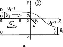
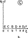
We start by considering a flow of finite width past a trailing edge with a flap. This scheme corresponds to the second power-augmented flow model, discussed at the beginning of this section. The flow picture and the auxiliary plane C are shown in Fig. 8.10, where X = —x/h, Y = y/h — 1, bf = bf/h, bf sin Of < 1. In the latter relationship the equality sign corresponds to the case, when the flap touches the ground.
Application of the method of singular points gives the results, presented below. The complex conjugate velocity in the ( plane can be derived in the form
![]() d w /( — 1 £ + св*/п
d w /( — 1 £ + св*/п
d2 = VC+T
The derivative of the complex velocity potential with respect to the auxiliary variable ( is obtained as
![]() d w (2 — a2
d w (2 — a2
dc= ac2-b2y
![]()
|
0 c a 1 b £ b. Fig. 8.10. The flow region past a flap of the wing in the extreme ground effect: physical and auxiliary planes. The resulting mapping function is /£-fl £ — ce*/* £2 — a2 |
|
t t + c) In addition, for £ = 6, v** = dw/dZ, or 6—1 b + cef/n |
|
||
|
||
 |
|
|
 |
||
|
||
|
||

Note that in this problem the channel flow velocity near the flap is calculated as one of the results of the solution. In a two-dimensional problem the magnitude of <5) is assumed to be known because the flow rate and the velocity on the jet boundary are the same as those in front of the wing. Then from conditions (8.101)-(8.104), we can obtain the following system of three equations for the determination of constants a, 6, and c:
 (8.106a)
(8.1066)
(8.106c)
|
/1 +t t — cefl* V1 — t t + c) |
where
Knowing a, 6, and c, we can determine the remaining unknowns using the formulas
|
+- Ь2^’ |
(8.108) |
|
2- |
|
|
7Г |
(8.109) |
|
. 2 v |
|
|
(‘-fK |
(8.110) |
Following we consider a separate small wing (winglet) in front of the leading edge. This winglet may be used to control the efficiency of power-augmented mode. In a corresponding local flow, this device is approximately represented by a point vortex of a given circulation Г. The flow pattern and auxiliary plane C are presented in Fig. 8.9.
The images of the vortex and the stagnation point, appearing in the flow domain due to it, have (in the auxiliary plane) coordinates Co = 9 +1/ and Ci = d + ic. In the physical plane z, the vortex of circulation (—Г) is located at a point Zg = Xq + iYg – The method of singular points gives the following results. The complex conjugate velocity in physical plane can be obtained in the form
du; _ c-i C + a (C — Co)(C — Co) (C + CiXC + Ci) d z C + lC-a (C + Co)(C + Co) (C-CiKC-Ci)’
where C designates the conjugate complex coordinates. The complex potential and its derivatives in the C plane are represented by the following expressions:
|
This local problem is of interest in connection with the possibility of increasing the reserve of efficiency of the power-augmented modes by providing shock-free entry of the tip of the leading edge. The scheme of the flow and the auxiliary plane are shown in Fig. 8.8, where x = (x — l)/h, у/hi, hi = h( 1), and Ъы is the length of the deflected part of the leading edge as a fraction of the leading edge ground clearance h. Here are the main steps and the results of the solution obtained by the method of singular points of S. A. Chaplygin. The complex conjugate velocity in the auxiliary plane can be derived in the form
d w + C + dx’W71′
dZ ^ CTb C-a 4 + 1 C-d)
![]()
|
|
|||
|
|||
|
|||
|
|||
|
|||
|
|||
|
|
||
|
|||
|
|||
|
|||
|
|||
|
|||
|
|||
|
|
||
|
|||
|
|||
|
|||
 |
|||
|
|||
|
|||

![]()
![]()
![]()
|
d£ — ^ief* |
|
t(t2 — c2) a + t t — 1 d + ts The magnitude of v* is determined by matching. For the remaining six unknowns, six equations are obtained, namely, (8.68), (8.71), (8.72), (8.73), (8.76), and (8.77). Accounting for the relationships |
|
v*0 + M v* — M ’ |
|
![]()
![]()
![]()
where
л/г b — c fl—cd–ceie/n
b = c/ ^l-v*/5h
we can reduce this system to one containing three unknowns a, c, and d and including equations (8.76), (8.77), and the additional condition
M – V* = 0. (8.78)
a — c
The suction force at point A can be determined by the formulas of S. A. Chaplygin
![]() die dw
die dw
dZd? dc’
 |
|||
Consideration of the last formula shows explicitly that it is possible to choose an angle of deflection of the leading edge tip that corresponds to shock-free entry, that is, zero suction force. This takes place at a = b. For a given length of the deflected part of the edge (forward flap) 6ief, this angle can be determined from the solution of the system
The normal force coefficient for the deflected part of the leading edge normalized with respect to bef is
![]()
![]() N fd (t-b)2 t-a (t-l d + te’°/* ,
N fd (t-b)2 t-a (t-l d + te’°/* ,
Ji t(t2 – c2) t + l ІГЙ cT^t)
and for zero suction force,
_ N_ fd t2~b2 (1~ 1 Af
П° Ъы Ji t(t2 — c2) t + ld — t)