Our heavyweight helicopter equal in the world does not have
In Rostov started production of the most load-lifting rotary-wing car The Russian holding «Helicopt[...]

Everything about aircrafts and helicopters. News and events in aviation worldwide. Civil, transportation, military helicopters and airplanes.

Everything about aircrafts and helicopters. News and events in aviation worldwide. Civil, transportation, military helicopters and airplanes.

Everything about aircrafts and helicopters. News and events in aviation worldwide. Civil, transportation, military helicopters and airplanes.

Everything about aircrafts and helicopters. News and events in aviation worldwide. Civil, transportation, military helicopters and airplanes.


The local flows near the leading and trailing edges for the conventional (without power augmentation) cruise of a wing-in-ground-effect vehicle were considered in sections 2 and 3. Here attention is paid to some local problems that describe the unseparated flows near the leading and trailing edges of the wing in the power-augmented mode, when the incoming and (or) escaping stream has a finite width.
8.1.2 Unseparated Coanda Flow Past a Leading Edge
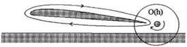
This regime of flow in the power-augmented mode was observed experimentally in [153, 155, 156] and represents a practical interest from the viewpoint of enhancing the efficiency of takeoff. The corresponding flow pattern and auxiliary plane £ are shown in Figs. 8.7, with
![]() 1-х
1-х
hi ’
where hi is a the local elevation of the leading edge above the ground (the leading edge relative to the ground clearance).
The approach for deriving the solution is similar to that applied in previous sections. In what follows, the main results of this solution are presented.
|
The complex conjugate velocity and the potential derivative in the auxiliary
Therefore, |
 |
Equations (8.50), (8.51), (8.52), and (8.53) enable us to determine four constants out of five. The fifth unknown, u*, is determined from the procedure of matching. Due to the circulatory flow at the leading edge a suction force occurs (the image of the tip of the leading edge in the ( plane is located at a point £ = a, ?7 = 0). The suction force coefficient can be derived by singling out the intensity of the square root singularity at the leading edge.
For C -> a,
 d w л a — 1 1
—=r ~ 2 a————— ,
d Z a-f 1 £ — a
![]() (a+ 1)2
(a+ 1)2
4a2(a2 — c2)
is the intensity of the square root singularity. The coefficient of the suction force in 2-D flow is given by
Cs = 2тг A2. (8.57)
The parameters contained in the formula for A are found in the form
It is easy to see that this result coincides with formula (4.62) with U(t) = 1 (steady flow). Thus, it turns out that within the assumption Suj = 0(1), the suction force acting on the leading edge in a flow of finite width is identical to that for unlimited flow.
We write the asymptotic expansion of the function dw/dZ (the complex conjugate velocity) in more detail. From (8.47) for ( a,
Based on this expression, we can single out a constant component of the horizontal velocity near the leading edge,
![]() a2 + 4a – 1
a2 + 4a – 1
U’ = ~(^+W~
Taking into account (8.47)-(8.49), the velocity and pressure coefficient in the local flow problem can be determined by the following formulas valid on AB: £ = £; £ є [a, oo), ri = 0,
 where
where
When modelling power-augmented lifting flows by using flow schemes 1 or 3 (see Figs. 8.1 and 8.3), it is necessary to have a solution of the flow problem for the jet escaping from under the flap or the endplate. Earlier, some results of the solution of this problem by Gurevich [138] were used for determining the contraction of the escaping jet and of the pressure drag component due to the rear flap. Here we give a complete solution of this local problem by a method different from [138]; see Fridman [157]. Note that knowledge of characteristics of this type of local flow is quite practical because both available experimental data and theoretical results show the significant influence of effective gaps under endplates and flaps upon the efficiency of cruise and power-augmented modes of motion. In addition, the structure of equation (4.53) and expressions for determining the aerodynamic centers and static stability criteria show that it is possible to control both the lifting capacity and the stability of longitudinal motion by devices that provide variation (chordwise and in time) of the gaps under the endplates.3
The flow problem under consideration and the corresponding auxiliary plane £ are depicted in Fig. 8.6 with designations : X = x/h,Y = y/h\ the stretched length of the device is bf = bi/h for the flap and hep(x) = hep(x)/hi(x) for the endplate. In the latter case, hep and h are the local length of the endplate and the local ground clearance of the wing at the cross section x = const.
|
The complex conjugate velocity in the auxiliary plane isExpression (8.40) determines the width of the effective gap |
and the flow |
|
contraction factor. We evaluate the behavior of the free surface far from the flap (endplate). On part of the boundary in the auxiliary plane, corresponding to the free surface (|AB|), rj = 0. Therefore, |
![]() 2fb(0 = -N ^ 4, c2 £Zl) ^ – 6f exP(Wf/^)»
2fb(0 = -N ^ 4, c2 £Zl) ^ – 6f exP(Wf/^)»
 |
|
where £ Є [0, oo). Taking into account the identity
Therefore,
Y{s ~ -1 + Sf + — exp(Xfs/N). (8.46)
7Г
The latter result shows that for the escaping flow under a flap or an end – plate, Xu —> —oo, the jet boundary resolves into a horizontal line exponentially. From the physical viewpoint, this means that perturbed zero pressure conditions apply immediately outside of the flap or the endplate.
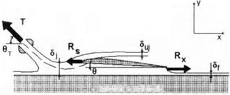
In order to analyze the possibilities of controlling the lifting capacity of a winged vehicle in the ground effect and of enhancing the efficiency of power- augmented modes of operation, the local problem of practical interest is that of flow past a leading edge with a deflected tip. Herein, this problem is treated within the reentrant jet formulation. The anticipated effect consists of generating of pressure thrust on a deflected part of the leading edge with the goal of reducing the drag and, consequently, the installed thrust required to provide power-augmented lift of a vehicle of a given weight. As in the previous analysis, the problem is solved by the method of singular points. The flow patterns in the physical plane £ and the auxiliary plane ( are shown in Fig. 8.5.
Stretching of coordinates is carried out in the following way:
![]()
![]()
![]() x — 1
x — 1
The complex conjugate velocity in the auxiliary plane ( is
(8.19)
The exponent accounts for the violation of conformity at point О with C = 1, where the angle between the adjoining parts of the solid surface changes when passing from Z to the auxiliary plane £. The derivative of the complex velocity potential in auxiliary plane £ is
![]() dttf C(C2-a2)
dttf C(C2-a2)
dC (C2+d2)«2-b2)’
 |
Therefore,
a. b.
![Подпись: The unknown constants are determined from the following conditions: 1 / dw TTN a2+ d2 = ~ 2i Jid dC _ 2 b2 + d2 ~ rJ’ (8.22) 1 f dw nN b2 — a2 ~ 2i Л dC ^ “ 2 b2 + d2 ~ V°' (8.23) It follows from the condition of mass conservation that Qc = QB + QD, Qc = Sy (8.23a) Therefrom ■= „ _ irN = QB + QD = — (8.24) and, in addition, x b2 + d? * 5> 62 — a2 V°’ (8.25) because ^(id) = ехр[-(тг - /3j)i] = - exp(i/?j), (8.25a) — arctan d + arctan — = ^le ——, 7Г a 2 (8.26) and * dw/l4 b — a/b— Іч^іе/тг V° = iZm = b + aU + l) ' (8.27) The velocity v* is determined by matching with the channel flow, for example, with a solution of equation (4.95). Because ZA = bef exp(—іве) and а N = —28-Jit, there is one more equation](/img/3131/image904.gif) |
![]()
 (8.28)
where bief is the chord of the deflected part of the leading edge (as a fraction of the distance of the hinge point above the ground). Thus, the system of three equations (8.25),(8.27), and (8.28) was obtained for determining the three unknowns a, 6, and d. The magnitude of /3j is determined from (8.26). The coefficient of the normal force acting on the deflected part is given by
![]()
Щ Ґ t(t-a)2 /1
7Гbef Jq (t2 + d2)(b2 – t2) VI + t)
These results facilitate the analysis of the influence of parameters of the deflection of the leading edge tip upon the efficiency of power-augmented regimes.
Notwithstanding a certain degree of idealization, the scheme with the reentrant jet (scheme 1) gives the possibility of obtaining the results which are sufficiently plausible and compatible with experimental data on PAR efficiency. We consider some relevant local problems of flows around the leading and trailing edges. Solutions of these problems were obtained by Fridman [157] by the method of S. A. Chaplygin of singular points within the frame of the ideal jet theory.
8.1.1
 |
Reentrant Jet Flow Near the Leading Edge
We consider scheme 1 of the power-augmented flow past a wing in the extreme ground effect. We introduce stretched local coordinates near the leading edge as
where hi = h*( 1) is a local ground clearance at the leading edge and Ls is the stretched distance of the stagnation point from the tip of the leading edge. The plane of physical flow is depicted in Fig. 8.4.
Assume as known the width of the incoming jet 5j and the velocity on its boundary C/j = 1. To determine the relative velocity potential of the flow, we apply the method of singular points of S. A. Chaplygin, which employs the idea of determining a holomorphic function in the complex plane, knowing the function’s zeros and poles and applying Liouville’s theorem; see Gurevich [138].
We map the domain of the flow in the physical plane z = x + iy onto the first quadrant of an auxiliary complex plane £ = £ + irj, so that the solid boundary AOBC of the flow in the Z plane is transformed into a positive semiaxis £ > 0 and the free surface part ADFC of the boundary in the physical plane be transformed into a positive semi-axis rj > 0. Taking into consideration that the complex conjugate velocity in the physical plane dw/dZ has a zero of the first order at the stagnation point (£ = 1) and performing an analytic continuation of this function onto an entire plane £, we obtain
![]() d w £ — 1
d w £ — 1
dz=‘cTT
The complex conjugate velocity of the flow in the auxiliary plane £ is found as
dw = ДГ C(C2 – 1) dC (C2+d2)(C2-62)
![]() Expression (8.2) can be commented on in the following way. The complex potential w should have a zero of the second order at the point ( = 1, that is, w = 0[(£ — l)2]. Because there is no violation of conformity at this point, the complex conjugate velocity may be assumed to be dw/d( = 0(£ — 1), i. e., having a simple zero at ( = 1. At the point ( = id, which is the image of infinitely distant point D of a free jet, the function dw/d( must have a pole of the first order (a stream with a finite flow rate). Physically, such behavior corresponds to that of a sink in an auxiliary plane and models the disappearance of the jet on the second leaf of a Riemann surface. In addition, the function dw/d( has another simple pole at the point ( = 6, which corresponds to a stream of a finite flow rate inside the channel. The resulting expression (8.2) was found by analytic continuation of singular points of the function dw/dC with the subsequent application of the Liouville theorem.
Expression (8.2) can be commented on in the following way. The complex potential w should have a zero of the second order at the point ( = 1, that is, w = 0[(£ — l)2]. Because there is no violation of conformity at this point, the complex conjugate velocity may be assumed to be dw/d( = 0(£ — 1), i. e., having a simple zero at ( = 1. At the point ( = id, which is the image of infinitely distant point D of a free jet, the function dw/d( must have a pole of the first order (a stream with a finite flow rate). Physically, such behavior corresponds to that of a sink in an auxiliary plane and models the disappearance of the jet on the second leaf of a Riemann surface. In addition, the function dw/d( has another simple pole at the point ( = 6, which corresponds to a stream of a finite flow rate inside the channel. The resulting expression (8.2) was found by analytic continuation of singular points of the function dw/dC with the subsequent application of the Liouville theorem.
Dividing left and right sides of formula (8.2) by corresponding sides of formula (8.1) and integrating the resulting expression taking into account the requirement Z( 1) = 0, we obtain the relationship between the planes Z = Z(C) in the form
N Si (C2^2)(C2-62)dC – ^
We find the constants
ъ-т-и-н [ (M
The condition of mass conservation is given by2
 |
wherefrom _
*rj К
і + <p b2 -1′
The requirement, accounting for angle /?j of orientation of the reentrant jet, is
^J(id) = exp[-(7T – $)i] = b-L (8.9)
 |
The flow velocity on AB (the “wetted” surface of the wing), ( = £, 77 = 0, f Є [0,6), is
![]()

where £ is determined from
The solution derived herein gives the possibility of calculating the local pressure distribution on the wing and the ground near the leading edge, as well as the inclination angle /?j and the flow rate of the reentrant jet as functions of the flow rate of the incoming jet and the elevation of the leading edge above the ground.
One of the problems that developers of wing-in-ground-effect vehicles have to solve is related to necessity to reduce the power required for detaching the craft from water. An efficient way to facilitate takeoff consists of blowing air under the main wing of the craft from special engines. This mode of vehicle operation is often called power augmentation or, briefly, PAR. Power augmentation provides additional dynamic head to support the vehicle at small speed and alleviates hydrodynamic loads due to the impact of waves upon the structure of the craft. From the viewpoint of aerodynamics and hydrodynamics, the problem of power-augmented takeoff is extremely complicated. It features the interaction of turbulent jets with the vehicle and water surface, the resulting spray effects, and the transient motion of the vehicle. In what follows, only very simplified models of power-augmented flows will be considered for a lifting system moving very close to the underlying surface.
When modelling the aerodynamics of wing-in-ground-effect vehicles in regimes of takeoff and transition to cruise by using power augmentation of the main lifting system, different schemes of the flow of air blown from the upstream PAR engines onto a wing may be adopted. Some of these schemes are depicted in Figs. 8.1-8.3.
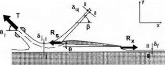
The first scheme of power-augmented flow suggests that the suction force at the leading edge is not realized and that interaction of the exhaust from the engines with this edge manifests itself in the generation of a reentrant jet, oriented at a certain angle /?j with respect to the downstream direction. It can be assumed that the far-held direction of the jet is subject to the requirement of the conservation of total momentum. The scheme with the reentrant jet was used by Gallington et al. [154, 156] in the analysis of the efficiency of power-augment at ion regimes. These authors considered simplified cases of how around a hat plate at zero incidence and dehected hap, assuming that there is no leakage from the gaps under the endplates.
The second scheme of PAR flow can be introduced on an assumption that the suction force is completely realized, and, moreover, that part of air jets from the upstream engines hows along the suction surface of the wing and continues to propagate downstream without separating from the upper surface of the hap. The argument behind the second scheme, shown in
K. V. Rozhdestvensky, Aerodynamics of a Lifting System in Extreme Ground Effect © Springer-Verlag Berlin Heidelberg 2000
|
Fig. 8.1. Scheme (1) of power-augmented flow with a reentrant jet, [153, 154, 155]. |
|
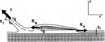
Fig. 8.2. Scheme (2) of power-augmented flow with the realization of a suction force and unseparated streamlines along the upper surface of the wing and the flap. |
Fig. 8.2, is certain experimental evidence that the jets envelop the rounded leading edge due to the Coanda effect (see Krause [156]).[41]
This scheme does not seem to be completely plausible for takeoff regimes at small relative ground clearances, when sudden decceleration of the turbulent jets generated by the upstream engines and rather slow motion of air in the channel under the wing is observed. These circumstances together with the fact that the flap deflection angles at takeoff are quite considerable (of the order of 20-30°) does not give a basis for assuming nonseparated flow past the suction surface of the wing.
At the same time, a well-known property of the Coanda effect, especially for relatively thin upper part of a bifurcating jet, to delay separation on the upper surface of the wing, does not allow us to reject consideration of flow models with the realization of the suction force.
In this connection the third scheme of power-augmented flow shown in Fig. 8.3 may be considered. This scheme may be based on a suggestion that the Coanda effect forces part of the bifurcating jet to envelop the leading edge of the wing, but for a certain combination of system parameters separation
 ! – к ІІиШИІІІІІ ІмШШІІІИЯ
Fig. 8.3. Scheme (3) of power-augmented flow with the partial realization of the suction force and the jet leaving the rounded leading edge (Coanda PAR flow model).
of the jet from suction surface of the wing may occur at some angle /3sep. In the third scheme it is assumed that the flow past the flap is separated.
To develop a description of power-augmented air flow past a vehicle in the extreme ground effect, it is appropriate to use the method of matched asymptotic expansions, taking the relative ground clearance h as a basic small parameter, i. e., treat the PAR problem in a fashion, which has been adopted throughout this book. Then the channel flow under the wing with small gaps under the endplates can be assumed to be described with a certain degree of adequacy by equation (4.53) or (in the steady case) by equation (4.65). The solution of these equations enables us to determine both the span-averaged velocity and pressure and, eventually, the lift, moment and induced drag. To calculate the flow parameters near leading and trailing edges and associated suction force and ideal pressure drag on the flap, it is necessary to consider the corresponding local flow problems. Local flow formulations can be used, e. g., for determining the appropriate deflection of the leading edge flap for shock-free entry of the flow and analysis of other possibilities of controlling the efficiency of cruise and PAR modes of performance of wing-in-ground – effect vehicles. A set of relevant local leading edge and trailing edge flow problems for power-augmented regimes is summarized in Figs. 8.4-8.10. In what follows, solutions are presented of selected local flow problems.
The aperiodic behavior of aerodynamic characteristics versus time can result from aperiodic motions of the lifting surface (takeoff, landing, acceleration – decceleration, the variation of cruise parameters due to the action of control surfaces) and also due to aperiodic perturbations, caused by unevenness of the ground or gusts. If the problem is linearized with respect to the perturbations, then the Fourier integral transform method can be used for the analysis of the response of the lifting system to the aperiodic perturbation or motion. In what follows, the analysis will be restricted to the aerodynamics of a lifting surface in the ground effect under the action of aperiodic perturbations (irregularities or steps on the ground or gusts). The solutions of the problems of motion of the wing in close proximity to a wavy sinusoidal wall or under the action of a vertical sinusoidal gust for arbitrary Strouhal numbers can be used as transfer functions for the application of the Fourier integral.
It is well known that if a stable system that has behavior described by a linear differential equation with linear boundary conditions is subject to the prolonged action of harmonic perturbation, then the response of the system will change in time harmonically and with the same frequency. Consequently, within the linear theory, the aerodynamic characteristics due to harmonic perturbation, say the lift coefficient CVe(t), can be written as
CVe(t) — eGy(k)exp(ikt),
where Gy(k) is a complex transfer function of the lift coefficient and є is the amplitude of the kinematic parameter, characterizing the harmonic perturbation. For example, when a wing is subject to the action of regular waves on the ground surface, the parameter є can be set equal to the wave amplitude aw, whereas for a vertical harmonic gust, є can be equated to the maximum velocity in the gust ug, к is the Strouhal number, corresponding to the perturbation under consideration, and і = is an imaginary unit. Transfer functions of moment coefficients can be introduced in a similar manner. We consider a lifting surface, moving at a constant speed and without slipping, in close proximity to the ground and subject to action of aperiodic perturbations such as an arbitrary irregularity on the ground or a vertical gust of arbitrary form. For simplification, assume that motion of the wing takes place in a direction perpendicular to the front of the perturbation. Assume also that the speed of the perturbation is negligiably small compared to the speed of the lifting surface,[40] so that the waves can be viewed as still with respect to the wing. Introduce a fixed coordinate system хі, г/і, and z in which the directions of all axes coincide with those of the moving coordinate system x,2/, 2, introduced earlier. Planes xOzi and хОу coincide with unperturbed position of the ground plane and the plane of symmetry of the wing, respectively. Let the perturbation have the following form in a fixed coordinate system:
V{xi) = Є/ОEl),
where again є is a parameter that characterizes the magnitude of the per – turbatiOon, for example, the relative (in terms of the root chord) height of an irregularity on the ground surface, and f(xi) is a function of the order of 0(1) describing the form of the perturbation. Let the form function of the perturbation be absolutely integrable on the interval — oo < x < oo, that is,
oo
f{xidxi < oo.
-oo
Then, in a wide class of piecewise continuous functions, f(xi) is representable by the Fourier integral, see, for example, Smirnov [150]:
1 f°°
f(xx) = — Q(k) exp(ifcxi) dfc, (7.52)
27Г /_nn
where
ос Q
/(xi) exp(—ifcxi) dxi, k=—~. (7.53)
-oo Uo
The function f2(k) is a Fourier transform of the function f(xi) and conversely. Counting time from the moment t0, when the leading edge of the root chord is located just above the frontline of the perturbation and passing over to the moving coordinate system,
є r°°
V(x, t) = — Q{k) exp[ifc(x +1)] dk. (7-54)
2тг 7-ос
It follows from consideration of expression (7.54) that in the coordinate system, attached to the wing, the function V can be viewed as the result of the superposition of harmonic perturbations of the traveling wave type and the quantity єП(к)/2іг represents the amplitude of a harmonic of relative frequency k. Knowing the transfer function, i. e., the aerodynamic response of a lifting system to the action of a traveling wave of perturbation of arbitrary frequency and unit amplitude, it is easy to derive the following expressions for the coefficients of the unsteady lift and the moment upon a wing which is subject to the action of a perturbation of arbitrary form f(xi):
|
E Cy(t) = — Gyfi(k)exp(ikt)dk7 2ТГ 7-ос |
(7.55) |
|
є mz{t) — 77“ GrrizQ(k) exp(ifct) dfc, 2^ 7 — 00 |
(7.56) |
where Gy and Grriz are complex transfer functions of the lift and the moment coefficients. As seen from (7.55) and (7.56), to determine the transient aerodynamic characteristics of a wing subject to the action of an irregular perturbation of a given form, we have to calculate the Fourier amplitudes
ад.
We find the form of the function i?(fc) for perturbations of simple shape. According to (7.53), the amplitude of the harmonic of relative frequency к can be written in a complex form
|
/ |
oo
f(xi) exp(—ikxi) dxi = !?i(fc) + ii?2(&)* (7.57)
-oo
For an “even” perturbation, /(—x) = f(xi),xi Є [—Z/P, LP], and
roo rLp/2
Q(k) = f2(k) = 2 f(xi) cos kxdx = 2 f{xi) cos kxi daq,
Jo Jo
(7.58)
where Lp is the length of the perturbation. For an “odd” perturbation, f{xl) = – f(-xi),xi Є [—Lp, Lp], and
![]() pL p/2
pL p/2
Q(k) = il?2(fc) = -2i f{xi) sinfcxi dxi
Jo
As examples of “even” perturbation consider
• cosine perturbation, defined as
, . _ Jcos(7TXi/Lp) for |жі| < Lp/2,
0 for |xi| >Lp/2.
Integration gives the Fourier amplitude in the form
![]() ад = 2 [
ад = 2 [
Jo
triangular perturbation, given by the function
![]()
f(xi) -■
As an example of an “odd” perturbation, consider a sine-type perturbation of the form
_ f sin(27TXi/Lp) for xI < Lp/2,
0 for |xi|> Lp/2.
Calculation of the Fourier amplitudes in this case results in
![]() Q{k) = Ш2{к) = sin (k^-).
Q{k) = Ш2{к) = sin (k^-).
Besides the “even” and “odd” forms considered above, it is interesting to consider a step-type perturbation. The form of such perturbation is described by a Heaviside step function
Representation of the step function by the Fourier integral is known to have the form

![]() dfc,
dfc,
wherefrom ш
П(к) = іП2 = – т – (7-63)
к
Before one performs calculations for concrete cases of irregularities on the ground or vertical gusts, the origin of the fixed coordinate system should be shifted to the front of the perturbation and the transform Q{k) rewritten accordingly:
f2*(k) = fi(k) exp(ifc^),
where f2*(k) is the amplitude of a harmonic in the new coordinate system. Separating the real part of the expression for the transient lift coefficient, we obtain the expression
 ?k{Gy(k)Q(k) exp[ifc(£ + Lp/2)]} dk. (7.64)
Taking into account the preceding results for the unsteady lift coefficient of a wing in motion over wavy ground obtained in paragraph 7.1, we can write the lift coefficient transfer function in the form
Gy(k) = ^[A(k)-iB(k)}, (7.65)
where for a rectangular wing, the parameters A(k) and B(k) depend on the Strouhal number and the aspect ratio and are determined by using the previous analysis of the aerodynamics of a wing in motion above the waves. For example, for a wing of infinite aspect ratio advancing in close proximity to sinusoidal wavy ground, the formulas for A(k) and B(k) are
A — A cos к — B sin fc, В = A sin к + Bi cos fc,
where
Ai = 2^-—^~) ~ i + k2 ^sin^ + ^ ~ ^2)cosfc ~ i];
Bi = ^ _ l) + jTjTpK1 _ k2) sinfc + fc(l – 2cosfc)].
Denoting the height of the irregularity on the ground as Oh and employing the wave amplitude aw as є, we can rewrite (7.37) as
CM) = [ (n1{k)A(k)cos{kt + ^) + B{k)sm{kt
|
—i?2 (k) A(k) sin(kt + —^) — В (к) cos(kt + j dfc, (7.66) so that in concrete cases • for an “even” irregularity Q{k) = i? i(fc), і?2(&) = 0, Cy(t) = Яі(*) [Л(к) cos (kt + ^) + B(k) sin (kt + • for an “odd” irregularity Q(k) = ii?2(fc), f2i(k) = 0, ■’) |
2-їїп J_00 L L 2
![]() A(k) Л(°) sin kt _ Ш1 cos jfetj dk },
A(k) Л(°) sin kt _ Ш1 cos jfetj dk },
where 1(£) is a Heaviside step function, defined as
 |
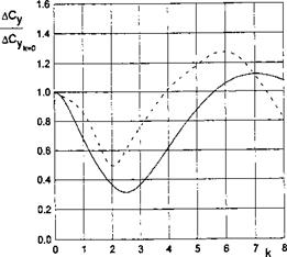
Some results of the calculations of the transient lift coefficient of a rectangular wing in motion above different types of uneven ground are presented in Figs. 7.19 and 7.20.
The vertical coordinate of each graph stands for Cy{t) /а^Суо, where Cy0 is a steady-state (cruise) lift coefficient of a flat rectangular wing in the ground effect and аь = ah/h is characteristic vertical dimension of the irregularity related to the ground clearance.
|
t Fig. 7.21. A history of the additional lift coefficient of a rectangular wing of finite aspect ratio, flying over a “step” in the extreme ground effect. |
An analysis of calculated data for an isolated irregularity shows that
• for wings of small-aspect ratio at initial moments, the additional lift first increases, then drops and tends to zero. In some cases the influence of the perturbation vanishes before the trailing edge of the wing finds itself beyond the irregularity;
• with an increase of the aspect ratio, the character of the curves changes somewhat. After the first maximum of additional lift, the second one appears, which is smaller in size. The influence of the perturbation may be observed longer than it takes for the wing to overfly the irregularity completely. For short convex local deformations of the ground and for certain time periods, negative magnitudes of additional lift due to the perturbation may appear;
• the magnitude of the maximal additional force due to the local irregularity increases with an increase in the amplitude of the irregularity and the aspect ratio and with a decrease of the relative ground clearance measured between the trailing edge and the unperturbed ground plane.
The data presented in Fig. 7.21 characterize the variation in time of the additional lift force for a step type irregularity.
It follows from Fig. 7.21 that with a decrease in the aspect ratio, the transition to the steady state takes place faster.
Conclusions formulated for flight above an irregularity on the ground generally remain valid when the wing is subject to the action of vertical aperiodic gust Presented here are only the results associated with the influence of the so-called step gust. In the case of a step gust the function that characterizes the distribution of the vertical velocities in the gust has the form of a
Heaviside step function
For this case, as shown earlier, the Fourier amplitude function takes the form described by equation (7.63). For an infinite aspect ratio Л = oo, the expression for the transient lift coefficient of a wing under the action of a vertical step gust can be derived in an analytical form. It can be shown that for A = oo, the corresponding complex transfer functions of the lift and the moment coefficients are given by
Taking into account (7.69) the expressions for the coefficients of transient lift and the moment coefficients for a wing of infinite aspect ratio under the action of a vertical step gust will be
|
– Vg0 [l(f) 1 f°° (k sinkt +cos kt) d/ j Hi 7Г У—oq 1 + № – |
|
|
— ^—-[l — exp(—t)] for t > 0; |
(7.70) |
|
2 у mz — -^[1 – exp(-£)] for t > 0, |
(7.71) |
where 1 (t) is a Heaviside function.
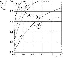
It is remarkable that for the case under consideration, the point of the application of the additional lift force due to the gust remains at the same time-independent position, namely, at a distance of one-third of the chord length from the leading edge. Some results of the calculations, carried out with help of formula (7.70) for A = oo and by numerical integration for rectangular wings of a finite aspect ratio, are presented in Fig. 7.22.
This figure features the dependence on time of the ratio Cy(t)/СУоо, where СУоо is a steady-state magnitude of the lift coefficient. In the same figure, the dashed lines designate similar results for an unbounded fluid obtained analytically by Kussner [152] for a wing of infinite aspect ratio (see Bisplinghoff et al. [151]) and numerically by the method of discrete vortices; see Belot – serkovsky [139]. A comparison of the results for the two limiting cases of the extreme ground effect (h 1) and an unbounded fluid (h = oo) shows that
for wings with small and medium aspect ratios, corresponding variations of the transient lift are steeper near the ground compared to the out-of-ground effect.
At the same time, comparison with calculations of Kussner demonstrates that for wings of very large aspect ratios transition to a steady state also occurs faster, although at the initial period of time, the curve of the transient lift coefficient goes upward more steeply for an infinite fluid.
![]()
|
To evaluate the ride quality of a wing-in-ground-effect vehicle versus the design parameters and the characteristics of waviness of the underlying surface, qualitative analysis will be performed in this paragraph of the acceleration
due to flight of a lifting surface close to wavy solid wall. Assuming for simplicity that in cruise all perturbations are sufficiently small, we consider both the linear aerodynamics and the equations of motion. In addition, the analysis will be confined to the pure heave motions of the vehicle under the action of the wave-induced lift.[36] In dimensional form, the instantaneous vertical position of the vehicle’s center of gravity is described by the following ordinary differential equation
A2nj N
(М + А22)-^£ = ;Г>Уп, (7.40)
71— 1
where M and Л22 are the mass and added mass of the vehicle, the latter corresponding to the inertial force in the direction of у axis in motion along the same axis, T~Lcg represents a dimensional distance of the center of gravity from the unperturbed ground surface, and T is dimensional time. The right – hand side of equation (7.40) contains external aerodynamic forces, acting in the vertical direction. We render (7.40) nondimensional, using the root chord C0 and the cruise speed U0 of the vehicle as characteristic quantities. Substituting the nondimensional parameters in (7.40), we obtain
In (7.41), СУп is the contribution of the lift force RVn to the total lift coefficient, S stands for the reference area of the wing, and p is the density of the air. Neglecting the added mass Л22 with respect to the mass of the vehicle, we obtain the following nondimensional equation:
A2u n
= <[37]-42>
П— 1
where /X = 2M/pSC0 is the doubled relative density of the vehicle based on the reference volume VT = SC0. Introducing the perturbation of the ground clearance h(t) = hcg — /г, where h is the time-averaged relative ground clearance, we rewrite (7.42) as
j2 I N
^ = ЕС».- <7-43>
n—1
We represent the right-hand side of (7.43) as the sum of three lift coefficients responsible for contributions of the aerodynamic action of the waves and the heave response of the vehicle,
Cy(t) = Cyjt) + ~^h{t) + CVh(t), (7.44)
where CVw is the wave-induced lift coefficient, and the second term represents the “spring” feature of the dynamic air cushion under the lifting surface in cruise, i. e., the response of the vehicle to the perturbation of the ground clearance.[38] The last term is due to the wave-induced heave rate and the acceleration. By using the results obtained in paragraphs 3.6 and 7.1, dedicated correspondingly to heave oscillations and the motion of a wing above wavy ground, we can write formula (7.44) in more detail:
Cy(t) = <^rCvl(A, к) exp(ikt) + к), (7.45)
where aw is the amplitude of the wave as a fraction of the root chord, і = л/—T, к = 27r/Lw is the Strouhal number, and Lw is the wavelength related to the root chord. In all cases we assume as meaningful only real part of the complex expressions. The parameters Cw and Сh represent the complex amplitudes of the wave-induced lift coefficient and the lift coefficient due to the heave. Assuming that the wave-induced oscillations take place for a long time so that free oscillations are damped, we restrict the analysis to “forced ” motions with the nondimensional frequency of the waves. For harmonic oscillations,
h = —k2h, so that the formula for heave motions induced by waves on the ground becomes
![]()
![]() ~ _ aw0Cw(Л, k) exp(ikt)
~ _ aw0Cw(Л, k) exp(ikt)
[ j ” h2[dCy/dh + k2n + iCh(,k)/h]
The maximum nondimensional acceleration due to heave is given by
ah = k2h(t).
Taking into account formula (3.65) for the lift coefficient Cy of a flat plate in a steady ground effect, we can derive an approximate relationship between the cruise lift coeficient and its derivative in height:
![]() _ Cyo
_ Cyo
dh ~ h ’
One can also link the (doubled) density (i of the vehicle and its cruise lift coefficient in the following way:
CyoFr2 = Ц,
 016
016
2n k= —
![]() Ц*
Ц*
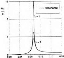
Fig. 7.17. The wave-induced heave accelerations of a rectangular wing versus the Strouhal number for different magnitudes of the aspect ratio (h = 0.2, /і — 75, Cyo = 0.65, aw = 0.03).
where Fr = UQ/y/gC0 is the Froude number based on the root chord. With this in mind, the maximum (dimensional) wave-induced heave acceleration Лъ as a fraction of the gravity acceleration g can be shown as
![]()
 |
Ah _ Qw^|Cw(A, k)/Cw(, 0)|fc2 g ~Cyo +/i/ifc2 + iCh(A, fc)|’
In some cases it may be more convenient to use the parameters Fr and Cyo than the relative density of the vehicle fi and the lift coeffcient Cyo. In this case (7.49) can be written in the alternative form
Ah awFr2CyoCw(,k)/Cw(,0)k2 g I — Cyo + k2hFr2Cyo + іСтДА, fc)| ’ j
Figures 7.17 and 7.18 illustrate the dependence of the acceleration level on the Strouhal number (the ratio of the wavelength to the chord) for different aspect ratios and ground clearances. In particular, Fig. 7.17 shows the behavior of the acceleration level versus the Strouhal number for different aspect ratios of the lifting surface. Figure 7.18 demonstrates the dependence of the wave-induced heave accelerations upon the Strouhal number for different magnitudes of the relative ground clearance.
An analysis of the calculations shows that for certain combinations of the cruise lift coefhcent, the relative density of the vehicle, and the relative ground clearance, the wave-induced heave of the vehicle can become resonant. It follows from the heave equation (7.43) that nondimensional frequency (the Strouhal number) of free oscillations kf is given by
 |
Fig. 7.18. Wave-induced heave accelerations of a rectangular wing versus the Strouhal number к for different magnitudes of the relative ground clearance (Л = 2, /X = 75, Cyo = 0.65, aw = 0.03).
or by using the relationship between dCy /dh and the lift coefficient in cruise C’yo >
When the nondimensional frequency of the forced oscillations approaches kf, the heave motion due to waves becomes resonant. For large first-generation ekranoplans the magnitudes kf are small. If, as an example, we take (i = 75, h = 0.1, and Cyo = 0.65, the resulting critical Strouhal number can be found to be 0.294 which corresponds to the ratio of the wavelength to the chord equal to 21.3. It means that for a wing chord of the order of 18 meters the resonant wavelength would be about 385 meters. Further consideration of calculated results demonstrates that with an increase in the relative density and relative ground clearance the wave-induced heave motions diminish. At the same time, increases in the wave height and the cruise lift coefficient lead to an increase in wave-induced motions.
The structure of the formula (7.49) reflects the character of the dependence of wave-induced heave motions on the most important design parameters, such as the relative density of the vehicle, the cruise lift coefficient, the aspect ratio of the main wing, the relative ground clearance, as well as upon the parameters of the waviness of the underlying surface, i. e., wavelength and amplitude.
It should be noted that heave accelerations, exemplified above, are associated with flight above a solid wavy wall. When considering the corresponding effects of sea waves, we should take into account that with a decrease of the wavelength (an increase in the Strouhal number) the height of the wave diminishes.[39] Therefore, the expected amplutude of the wave would be considerably smaller. It is also worth mentioning that the estimations discussed in this paragraph are very approximate and provide some qualitative information on the influence of different factors on accelerations due to the waviness of the ground.
7.1 The Influence of Waves on the Aerodynamics of a Lifting Surface
A large seagoing ground-effect vehicle has to combine sufficient seaworthiness with acceptable magnitude of the lift-to-drag ratio, when flying above rough seas. The approach of matched asymptotic expansions furnishes a simplified mathematical model of the unsteady aerodynamics of the wing-in-ground – effect vehicle, based on the idea of domination of the channel flow in the extreme ground effect. This concept seems to be promising for wave perturbations, because the influence of waves upon the aerodynamics of such a vehicle is in fact predominantly due to the corresponding variation of the geometry of the gap between the wing and the sea surface.
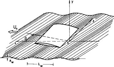
Following Rozhdestvensky [56, 57], we consider the schematized problem of a thin flat rectangular wing of aspect ratio Л, advancing with constant speed U0 and an angle of pitch в above a still, solid, wavy boundary.[31]
The wing and the coordinate system are presented in Fig. 7.1, where aw is the amplitude of the wave, Lw is the length of the wave, h is the clearance, measured from the trailing edge of the root section to the unperturbed level of ground surface, and (3 is the course angle measured in the horizontal plane у = 0 as the least angle between the direction of the wing’s motion and a normal to the front of a sinusoidal cylindrical wave.[32] As previously, one assumes that at any time the gap between the wing and the wavy ground is small compared to the chord. With these assumptions in mind, we can write the gap distribution between the wing and the underlying surface as
h*(x, t) = h + вх — aw cos[fc(£ cos(3 + z sin/? +1 cos/?)]
= hh*(x, t) = 1 + Ox — awcos(nx +pz + nt), (7.1)
|
where 9 9/h, aw — aw//i, к — k cos/3, p — fcsin/3, and к = 2tt/Lw is the
Strouhal number based on the ratio Lw of the wavelength to the root chord of the wing.
Using the lowest order model of the flow, we have to solve the problem described by relationships (2.114)—(2.117) with the gap distribution input given by (7.1). One of the approaches to the solution of this nonlinear problem for the motion of a wing over a wavy wall may be based on a consistent expansion of the velocity potential in terms of the two small parameters 9/h and aw/h; see Barrows and Widnall [136] and Rozhdestvensky [42]. In line with this approach, we seek the solution of the problem in the form of a series and leave only terms that are linear in the angle of pitch
V = 0<Po + 0<br<p§aw + • • •. (7.2)
Function <рё characterizes the linear (in angle of attack) part of the potential for steady motion above an unperturbed underlying surface. As shown in 3.4, the expression for can be readily derived for the uniform spanwise distribution of the angle of pitch in the form
2
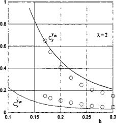
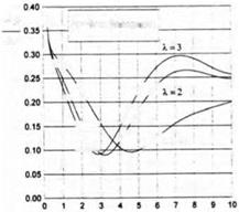
Figures 7.2 and 7.3 present the amplitude-phase characteristics of the wave – induced lift coefficient CVw (t) versus the relative wavelengths (Strouhal numbers) for different aspect ratios of a rectangular flat wing. The dashed lines correspond to calculations performed by using the formulas (7.30) and (7.31) for wings of a small aspect ratio. It follows from Fig. 7.2 that at a certain relative wavelength for a wing of a given aspect ratio the amplitude of the wave induced unsteady lift is minimal. With a decrease in the aspect ratio, this minimum shifts toward the range of shorter waves. For example, for a wing of an infinite aspect ratio, the minimum amplitude of the unsteady lift is reached at к ~ 2.4, Lw ~ 2.6.
For a rectangular wing of aspect ratio A = 2, this minimum is reached at к ~ 3.1, Lw ~ 2,[33] and for a square wing Л = 1 the minimum occurs at
Strouhal Number i<= _2j_
 |
L
L w
|
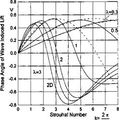
Fig. 7.3. The phase of the wave-induced unsteady lift coefficient of a rectangular wing versus the Strouhal number for different magnitudes of the aspect ratio (dashed lines: small-aspect-ratio approximation (7.31)). |
к ~ 4.5, Lw ~ 1.4. These results correlate with the calculated and experimental data of other researchers. According to calculations of Avvakumov [107], obtained by using the method of vortex segments and distribution of sources on wavy ground, the magnitudes of the Strouhal number, corresponding to
the aforementioned minima, were found as к ~ 3 for Л = 2 and к ~ 4.3 for Л = 1. In the work by Shumsky [148], dedicated to the nonlinear flow problem for a two-dimensional foil near a wavy wall (the method of vortex singularities in combination with step-by-step linearization in time), the minimum of the unsteady lift was estimated to occur at к ~ 2. In the experimental investigations of Belinsky et al. [149], carried out by using the method of an underwater screen (ground plane), it was shown that for a rectangular wing with an aspect ratio Л = 2, the minimum of the amplitude of unsteady lift occurs at the Strouhal number fc ~ 3.
The solution of problem (7.5)-(7.7) in the general case of an arbitrary angle between the direction of motion of a wing and the wave front was obtained in Rozhdestvensky [57]. A somewhat cumbersome derivation of the solution of this problem and some final closed form expressions for the lift and the moment contributions are given in the Appendix. Note that for oblique waves, the wing is subject to the action of a lateral moment.
In accordance with the general structure of the solution, the wave-induced lateral moment coefficient can be represented in the form
 |
where hi = к cos /3, Fmx (Л, fc, /3) and ^(A, fc, /3) characterize the amplitude and the phase of the lateral moment due to the presence of waves. Some typical results of calculations of the aerodynamic characteristics for oblique waves and a reference point coinciding with the leading edge (a = 1) are plotted in Figs. 7.4-7.7.
 |
Analysis of the results calculated for the wave-induced lift and the lateral
moment coefficients CVw and mXw leads to the following conclusions:
• With an increase in the course angle /3, the minimum of the amplitude of the unsteady lift for a wing of a given aspect ratio decreases and shifts toward the range of longer waves; this shift is more pronounced for wings of a larger aspect ratio;
• Up to the Strouhal numbers corresponding to the minima of the amplitude of the unsteady lift, a phase lag of the lift is observed with respect to the moment of time when the leading edge passes the wave crest. This phase lag vanishes when angle /3 approaches 7t/2 (in the latter case the problem becomes steady, which corresponds to Pmx equal to zero);
• In the range of Strouhal numbers considered, the amplitude curve of the lateral moment coefficient contains two maxima. The magnitude of the first maximum increases when the course angle tends to 7t/2. The position of the maximum shifts toward longer waves with an increase in the aspect ratio.
|
A* 6 ’ |
From the general formulas, corresponding to arbitrary course angles, we can derive limiting expressions for a wing of small aspect ratio and wavelengths much larger than the span:
The amplitude-phase characteristics, corresponding to an unsteady increment of the lateral moment, in the case of wings of small aspect ratio and
 |
long waves take the form
A4fcsin/3 _ 7Г Aft 7Г /‘ъд
_________________ Ф ~ — _j_ — = — – i_ —
192 ’ mx 2 2тг 2 27r*
Turning to the relative wavelength Lw, we obtain the following formula for the amplitude of the lateral moment for A —> 0 and к —> 0:
_ 7rA4sin /3 ЬтПх – 96LW ’
wherefrom it follows that for wings of a small-aspect ratio over long waves, the amplitude of the lateral moment is directly proportional to the aspect ratio to the fourth power and the sine of the course angle and inversely proportional to the relative wavelength.
Because the solutions presented above are linear with respect to the wave amplitude and are valid in practically an unlimited range of Strouhal numbers, it is possible to apply the Fourier integral to investigate the following:
• motion of a rectangular wing over a cylindrical deformation of otherwise flat ground or over a solitary wave, and influence of a step variation of the ground surface;
• motion of a rectangular wing over a sea surface with irregular waves on it. The solution of the latter problem in conjunction with consideration of the equations of the dynamics of the lifting system in ground the effect opens a possibility of developing the basics of normalization of the seaworthiness and the ride quality of wing-in-ground-effect vehicles.
The asymptotic representation (7.2) of the velocity potential ip can be continued to include the term of the order of O(0a^), which accounts for nonlinear effects in the wave amplitude. In this case, the corresponding expansion
_ q-2
for the lift coefficient should be supplemented by the term 6a^ Cya™.
In the simplest case of a wing of infinite aspect ratio A = oo, the expression for this additional term can be obtained in closed form:
Йп2 ~ ~ ~
Су w = A cos 2kt + В sin 2 kt + D
![]()
![]() 1
1
4k2 k(l + k2)
-0.4
![]()
![]()
![]()
 ~ cos 2 к 1 . 7 /7 m 1
+ +,i
The magnitude of D is constant for a given wavelength and characterizes the time-aver aged contribution to the wave-induced lift coefficient. For a positive angle of pitch D > 0.
Calculation by using formula (3.33) shows that for the considered case of a flat plate, a wing flying over sinusoidal waves is subject to action of a constant additional lift increment proportional to the magnitude of the cruise lift coefficient and the square of the ratio of the wave amplitude to the ground clearance.[34]
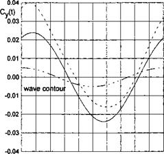
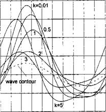
Figure 7.8 presents a history of the wave-induced unsteady lift coefficient related to the cruise lift coefficient Cyo for flying near flat ground with the same relative clearance h.
Calculations were performed by the formula
The calculated data correspond to a wing of infinite aspect ratio (Cyo = 6/h, h —> 0) and relative wave amplitude aw = aw//i = 0.5. The dashed line in Fig. 7.8 describes the wave profile, enabling us to determine the position of the maximum (minimum) of the unsteady lift with respect to the position of the crest or hollow of the wave.
|
Fig. 7.9. A comparison of theory with experiment for a rectangular wing over waves ( solid lines: theory; circles: experiment [137]; the abscissa of the reference point a = 0.5, Л = 2, k = 1.05). |
From a practical viewpoint, for example, for using the results of this solution in the dynamics of flight of a vehicle over waves, it is convenient to represent the aerodynamic coefficients by aerodynamic derivatives of the lift and moment coefficients with respect to the wave coordinate yw and its rate yw.
In this format, the lift and moment coefficients can be calculated with the help of the following formulas:
|
Cy — Cyo + Cy™yw + yw, |
(7.34) |
|
mz = mZ0 + mf1 yw + |
(7.35) |
|
mx = mxo + mv™ yw + m%wyw, |
(7.36) |
where Cyo, mZo, mXo are the cruise values of the aerodynamic coefficients yw = aw cos yw = —к aw sin
|
Cy„ |
Cy„ |
– e <30 ■ ~ K‘-k *■’ |
(7.37) |
|
|
myzw |
Q = £5 ®m*w. |
mfw |
(7.38) |
|
|
m*’w |
9 = Д2 |
m*’ |
‘ ЇаС’"’-‘ |
(7.39) |
where in all cases, the lift and moment coefficients are defined with respect to the same reference point a. When analyzing the dynamics of the vehicle, this point can be chosen to coincide with the center of gravity. Formulas for
|
Fig. 7.10. The doubled amplitude of the wave-induced lift coefficient versus the Strouhal number (Л = 2, 0° = 5°,/i = 0.2,aw = 0.1; solid lines: present theory; dashed lines: numerical calculation, [107]). |
the above coefficients in the case when the reference point coincides with the trailing edge, are presented in Appendix,[35] Recalculation from the trailing edge to the arbitrary position of the reference point a / 1 can be done by multiplying the complex amplitude of the corresponding coefficient by exp(—fca), see formula (7.22).
In Fig. 7.9 a comparison is presented of some results calculated for the aerodynamic derivatives with experimental data for motion of a rectangular wing near a wavy solid wall (a = 0.5, Л — 2,0° = 3.3°, (3 = 0, к = k = 1.05). The experiment was conducted by Grebeshov [137] by the method of an underwater screen.
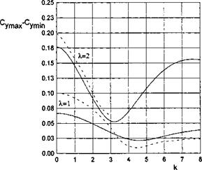
Figure 7.10 presents a comparison of the dependence of the doubled amplitude (Cr2/max — СУтіп) of the unsteady lift coefficient versus the Strouhal number with the calculated data of Avvakumov [107] (128 panels on the wing, 720 panels on the ground). In Fig. 7.11 instantaneous magnitudes of the wave – induced lift coefficient of the present theory are compared with calculated data of [107]. Figure 7.12 presents a comparison of results calculated by the present theory with the results of Shumsky [148], where a complete numerical analysis of a two-dimensional inviscid flow past a flat plate above a wavy wall was performed by the discrete vortex technique accounting for the structure of the wake.
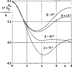
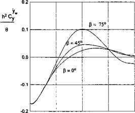
Figures 7.13-7.16 illustrate the influence of the Strouhal number and the course angle upon the aerodynamic derivatives of the lift and the lateral
![]()
|
|
|
|
A = 2.
 |
0 2 4 6 8
к
Fig. 7.14. The aerodynamic derivative C%w of the lift coefficient of a rectangular wing in flight over waves versus the Strouhal number for different course angles /3, A = 2.
moment coefficients of a rectangular wing of aspect ratio A = 2 in flight over wavy ground. Note that the quantities /i2C^w/0, h2C^w /0, h2m^w/в and к2т%” /0 do not depend either on the relative ground clearance or on the adjusted pitch angle. This feature makes the data representation more compact.
 |
0 2 4 6 8
к
Fig. 7.16. The aerodynamic derivative m^w of the lateral moment coefficient of a rectangular wing in flight over waves versus the Strouhal number for different course angles /З, X = 2.
When the lifting surface is slotted, the same formalism can be applied to account for the influence of gaps upon its aerodynamics in the ground effect. As indicated in Durand (1934), the problem of the slotted wing is of practical importance for several reasons. In the case of lateral slots with a proper choice of the adjusted angles of attack of portions of the wing, separated by the slots, a better lifting capacity can be achieved. On the other hand, introduction of longitudinal slots especially near the root section of the lifting surface, can result in an increase in induced drag.
It should be mentioned that numerical solutions of the flow problem for a wing with narrow slots can bring about computational difficulties and even divergence of the computational processes. In any case the number of control points should be considerably increased in the immediate vicinity of the gap to avoid numerical errors.
An exact solution for a two-dimensional foil with one small gap in an unbounded fluid was developed by Chaplygin. Bleviss and Strubble [145] obtained some exact solutions for longitudinal gaps on a wing of small aspect ratio in unbounded flow. Application of the method of matched asymptotic expansions opens certain possibilities for a simplified analysis of the flow problems for slotted wings both in and out of the ground effect. White and Landahl [146] handled corresponding 2-D problems by the matched asymptotics technique. In what follows, we use the asymptotic theory set forth in previous sections of this book to evaluate the influence of a lateral gap of small width 5g = 5gh, 5g = 0(1), located at a distance lg = 0(1) from the trailing edge, upon the aerodynamic characteristics of a thin rectangular wing of aspect ratio Л, moving at very small distances from the ground h <C 1; see Rozhdestvensky [45, 46].
As discussed previously, to account for the influence of the gap, we have to analyze the local flow near it, find the corresponding asymptotic solution, and subsequently, match it to the main flow. This procedure can be shown to be applicable in nonlinear case, but here analysis will be limited to a the linearized case. In compliance with the linear theory it will be assumed that the vortex sheet emanating from the leading edge of the lateral gap stays in the same horizontal plane. Sufficiently far from the intersection of the slot with the side edges of the wing, we will consider the local flow as a two-dimensional flow in the planes z = const, which are normal to the gap’s axis. Near the gap, the local stretched coordinates yg = y/h, xg = xg/h = (x — l)/h, zg — z are introduced. In the plane of the complex variable Z = xg + iyg, the complex velocity potential Fg and the complex conjugate velocity
dFg.
g dZ g g
of the flow near the gap are analytic functions, satisfying the following boundary conditions:
• on the ground {yg = 0 + 0),
a) 3Fg = = 0, b) ^swg = —vg = 0; (6.161)
• on the wing behind the gap (yg = 1 ± 0, xg < —Sg/2),
a) $sFg = ipg = l, b) ^swg = —vg — has{lg – f 0, г, £); (6.162)
• on the wing in front of the gap (yg = 1 ± 0, xg > <$g/2),
a) QFg = = 7g, b) Sfri;g = — ug = has(lg ± 0, z, t). (6.163)
Here 7g is an unknown constant associated with the rate of the fluid passing through the gap;
_ dys dys
as dx dt
is a prescribed downwash near the leading and trailing edges of the gap. The superscripts plus and minus correspond to points on the upper and lower surfaces of the wing, respectively. According to the scheme already discussed above, the gap flow solution will be decomposed into (a) homogeneous and (b) nonhomogeneous solutions. To proceed with the solution of the local problem, formulated above, we map the flow region onto an upper half plane of the auxiliary complex plane. The point-to-point correspondence is shown in Fig. 6.15.
 |
|
The mapping function was obtained by application of the Christoffel – Schwartz integral
Note that for sufficiently small 6g < 0.5, we can approximately set (3 = 7r<Sg/8. The solution of problem (a) was found in the form
Fag = I (in + 7g In ^I). (6.166)
It is easy to verify that this solution does not violate the flow tangency condition at points on the wing. The velocity potential on the surface of the wing is calculated by taking the real part of the complex potential and setting C — 6 Then,
V>ag = 1 (in фф + 7g In • (6.167)
The solution of problem (b) was found with help of the Schwartz integral for a half plane, which enables us to construct an analytic function by using its imaginary part, given on the real axis; see Fuks and Shabat [131]:
![]()
![]()
![]()
dCi + C
|
V5 bg |
Omitting the real constant C and separating the real part of expression (6.168), for points on the surface of the wing near the gap,
![]() <Pg — ^l^ag ^2^bg d – khxg – j – ^4?
<Pg — ^l^ag ^2^bg d – khxg – j – ^4?
where parameters li must be determined by matching procedures. Parameters /з and Z4 take different values above (yg = 1 + 0) and below (yg = 1 — 0) the gap, that is ф l% and 1% ф 14 . The real constant 7g was found by accounting for the requirement that the perturbation velocity should be finite at the leading edge of the gap (point C in Fig. 6.15 ) as
![]() _l-(3 7g~ ! + /?•
_l-(3 7g~ ! + /?•
It can be readily demonstrated that for such a choice of 7g, the perturbation velocity at the trailing edge of the gap (point В in Fig. 6.15) has a square
root singularity, i. e., behaves as s~1^2 (where s is the distance of the point from the trailing edge of the gap in the downstream direction). Asymptotic representations of the gap velocity potential (6.167) far from the gap, which are needed for matching with the main flow solution, can be written as follows:
• far from the gap on the upper surface of the wing (у = 1 + 0),
, 7r(l – /32)xg
n(l + /3) n 2(32
{as) otgi’lg 0) 0).
|
‘ 2/З2 і ‘j = *^g (<*s> 2 (^g 0) — ^2 J j H – hhxg H-14) %g ^ Vg = 1 A? |
• Far from the gap upon the lower surface of the wing (yg = 1 — 0),
: (as) In2 + as(/g ~ °) 1 ] } + hhxg + /4,
![]() Xg —>• —00, yg = 1 — 0.
Xg —>• —00, yg = 1 — 0.
The velocity potentials of the upper flow, channel flow, and leading and trailing edge flows can be constructed in a manner explained in detail in previous sections. For briefness we discuss only the changes to be introduced into the procedure for solution when the wing has a lateral gap.
The upper flow potential in region Vu is represented by a straightforward distribution of sources (sinks) over the projection of the wing plus the wake onto the ground with the addition of the admissible contour distribution of the sources (sinks) along the edges of the wing (wake) and along the axis of the gap. Expression (2.31) of section 2 for the upper flow potential should be supplemented by the term
-jzl dzo, rg = J(x-le)2 + (z – z0)2, (6.175)
47r J-/2 rg V
which represents the potential of a linear distribution of the sources (sinks) with a strength Qg and models (in the upper flow region) a leakage of the fluid through the gap from beneath the wing. The strength Qg of the singularity
distribution has to be determined by matching with the gap flow potential <pg.
Taking into account expression (6.175), the asymptotic representation of the upper flow potential near the gap is found in the form
Here, parameters L and L<i characterize the influence of distant sources (sinks). Corresponding expressions for are not presented herein for briefness.
The channel flow potential satisfies the same Poisson equation as that for the wing without slots. However, this equation, strictly speaking, has to be solved separately in two portions of the wing planform divided by the gap axis. The boundary conditions at the leading (side) and trailing edges of the wing are given by the same formulas as previously discussed. The only difference is that the constants A2,i? i, and B2 comprise contributions from the additional term (6.175) in the expression of the upper potential.
A special feature of the channel flow for a slotted wing is that both values of the potential <p and the corresponding pressures are, generally speaking, different when one approaches the line x = lg,z < A/2 from the left and from the right. Physically, this is connected with mass and vorticity transport through the gap. Rewriting expressions (6.174) and (6.176) in terms of the gap variable xg = hxg enables us to find asymptotic structure of the parameter 11 when xg tends to 0 + 0 and 0 — 0:
 |
Some results, calculated by using formulas (6.196) when the gap is located at the midchord of the plate (lg — 0.5) for different h and 6„ are given in Fig. 6.16.
As seen from this figure, within the range of clearances under consideration, the presence of the gap brings along a certain reduction of the lift and moment coefficients.5
Analysis of calculations of the factors ks and кт for different 0 < h < 0.12 shows that these quantities are only weakly dependent on the relative clearance. The latter circumstance provides a sound basis for using much simpler formulas, using leading order contributions (6.192) and (6.193). In particular cases, these expressions take the following forms:
• flat plate:
• flat plate with a flap f(x) = x for 0 < x < bf, f(x) = 0 for bf < x < 1, where bf is the chord of the flap. When the gap is located near the hinge of the flap, Zg = bf,
![]() 4/?(l ~ bf) 60(1-bf)
4/?(l ~ bf) 60(1-bf)
(1 + /3)(2 — b{) ’ m (l + /?)(3-b?)-
 |
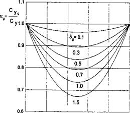
|
It follows from the expressions for Kg and кт that for a foil with a given camberline /(rr), a position of the gap exists for which the decrease of the aerodynamic coefficients due to the gap is most pronounced. For example, for a flat plate, the minimum of Kg is reached at /g = 0.5, whereas for an arc foil, this minimum is achieved at Z = 1/3. Figures 6.17-6.19 illustrate some results for ttg. It can be seen from analysis of the figures that the influence of the gap for a given width 5g and location lg depends on the shape of the camber line. For example, at lg = 0.5 and 6g = 0.3 for a flat plate, Kg = 0.9, whereas for a plate with a flap and lg = bf = 0.5, Kg = 0.85.
![]()
Ri = ^2 9n [tanh(9„ig) + tanh tanh(gn/g)
n=о L 2 J qn
![]()
|
 |
 |
g W«anh*,_ s
£o«*v «» ‘
_ tanh[g„(l – lg)]
Sn q* coshgn[l + (1 – /3) tanh(qnig) tanh(l – lg)/( 1 + /3)]’
qn = ^(2n+ 1).
Some calculated results using formulas (6.201) and (6.202) are given in Table 6.1 for lg = 0.5 and 5g = 0.3.
These data demonstrate that the influence of the lateral gap upon the aerodynamic coefficients diminishes quite noticeably with a decrease in the aspect ratio.
|
Table 6.1 The influence of a lateral slot upon the lift and moment of a rectangular wing in the extreme ground effect.
|
It is known that rotor devices in the form of rotating cylinders and rotating flaps attached to the main foil can be used as one of the possibilities to enhance and control the aerodynamic efficiency of lifting systems.
In connection with the importance of edge effects for the aerodynamic behavior of wings operating in the ground effect, rotor devices can be fitted on the leading, trailing and side edges to form rotating forward and rear flaps and rotating endplates.
In what follows, we discuss some simplified mathematical models of rotating devices fitted near the edges of a lifting surface in the ground effect. It is assumed, in particular, that when a rotating device is operating near a sharp edge, the Kutta-Zhukovsky type condition is satisfied at this edge at all times.
|
|
|
Fig. 6.13. A wing with a rotating flap at the trailing edge in the extreme ground effect. |
In the case of a rotating flap mounted in the vicinity of the trailing edge, this assumption implies that a supercirculation arises around the wing, which should eliminate large velocities induced at the trailing edge. It should be noted that the lift resulting from this supercirculation is much larger than a simple Magnus lift acting upon a rotating cylinder or a flap. The lift-to-drag ratio is significantly larger that for an isolated rotating flap due to a large chord to thickness ratio.
In the case of a rotor endplate, the mechanism of enhancing the lift is somewhat different. Here the requirement of finite velocities at the side edge of the wing (or tips of conventional endplates used for wing-in-ground-effect vehicles) slows down the leakage from under the side tips. Hence, we expect an increase in lifting capacity.
It should be noted that for both rotating flaps and rotating endplates, the resulting lift-to-drag ratio should be estimated accounting for the additional energy required for the rotation of the devices.
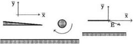
From the viewpoint of applying matched asymptotics techniques to the problem of flow past a wing-in-ground effect with rotating devices, the scheme of the solution should incorporate the analysis of the corresponding local flow in the vicinity of the wing tip with a rotor (rotating flap or rotating endplate); see Fig. 6.13.
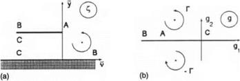
We turn to the derivation of the boundary condition for channel flow at the trailing edge with a rotating flap. Consider the case when the main lifting surface of a wing-in-ground-effect vehicle has a rear flap that can rotate around an axis located at its midchord. Replace the rotating flap by a vortex of circulation Г. In a local stretched trailing edge region, this vortex has a complex coordinate C7 = Щ + iy7, where v = — x see Fig. 6.14a.
We define the nondimensional circulation Г as
|
Fig. 6.14. (a) The stretched local region near the trailing edge with a rotating flap, (b) The auxiliary plane in the local problem of flow past a trailing edge with a rotating flap. |
where r0 is the nondimensional radius of an equivalent rotating cylinder equal to the semichord of a rotating flap, u> is the circular frequency of rotation, C0 is the chord of the main wing, U0 is the cruise speed of the vehicle, and к = uCq/Uq is the Strouhal number based on the chord. The local flow potential (p1 of the relative motion of the fluid can be sought in the form
<Pe = CLiifa + a2h(fb + IV7 + a3hv + a4.
The local flow near the trailing edge without a rotating flap was considered in section 2. Therefore, we have to determine only the additional term due to the rotor, that is, y?7. To solve for y?7, we map the flow field onto an auxiliary complex plane g = gi +i#2 shown in Fig. 6.14 b. This mapping is realized by the function
C=i(s + lnp + l). (6.143)
7Г
We find cp7 = 3?{F7(£)}, where the complex potential F7 of the vortex in the p-plane can be written as
F-y(9) = ^~In ^4^, (6.144) 2тгг g – 4 7
where g is the complex conjugate with respect to g. The complex coordinate g~, of the vortex in an auxiliary plane can be found from the equation
<7 = -($7 + In +1). (6.145)
7Г
Assume further that the rotation of the flap results in supercirculation around the wing. The magnitude and direction of this supercirculation is governed by the Kutta-Zhukovsky condition at the trailing edge. With this in mind, after complementing the right-hand side of (6.144) with a supercirculation term, we obtain
F-y(g) = ^- In ^ + <?7 Inp.
2тг г g g*y
Accepting the previously mentioned mechanism of the operation of a rotating flap, we find the constant C7 from the condition of no flow across the trailing edge of the main wing. Accounting for violation of the conformity of the mapping at point g = — 1 (image of the trailing edge), we can satisfy the Kutta-Zhukovsky condition by requiring that for g — —1,
![]()
![]() Щ = i_ + + = 0
Щ = i_ + + = 0
dg 2тг ig-g^ g-gy) g
wherefrom
7 2іті V -1 – gly – ig2j -1 – giy + іg2j
|
|
|
|
|
|
We consider the outer asymptotics of the flow velocity due to the rotor at some distance from the trailing edge along the upper and the lower surfaces of the lifting surface. We calculate the complex velocity in the physical plane
|
dF~ di+ dg ~dC~ = ~d*TdC |
|
|
![]()
On the surface of the wing in the vicinity of the trailing edge, we have to replace g with gi, so that
![]() dFy = dFy =______________________________ ,
dFy = dFy =______________________________ ,
dC dP [(gi -Зі7)2 +З27К1 +5i) l+5i
The upper surface asymptotics follows for g —» —00:
![]()
£ = u + i= — (5i + І7Г + In Iflri I + 1), i/~ — +0(1). (6.152)
7Г 7Г
It follows from (6.151), (6.152) that for V —00, у = 1 + 0 (gi —> —00, g2 = 0 + 0), the flow velocity behaves as
![]()
We turn to consideration of the outer asymptotics of the local flow velocity on the lower surface of the wing inside the channel, i. e., when g -» 0 — 0. In this case we can obtain from the expression for the mapping function
-(1 +І7Г + 1п|с/і|),
7Г
wherefrom
0i ra-exp(7rp), (6.155)
so that far upstream in the channel, g vanishes exponentially. Hence
Accounting for the obvious relationships v = —x = —x/h, dp1/dv = —hdp1/dx, we can represent the contribution of to the channel flow boundary condition at the trailing edge as
![]() = _I^7 =
= _I^7 =
дй h дй h 7
The corresponding boundary condition for the velocity of the relative motion of the fluid accounting for the structure of the local flow potential <pe can be written as follows:
where
In the previous expression, f0 = r0/h is an equivalent radius of a rotating flap (identical to a half-chord of the flap) related to the ground clearance and kro = uC0r0/U0 is the ratio of the flap edge linear velocity to the characteristic flow velocity U0. The parameter kro can be interpreted as a Strouhal number based on the radius of an equivalent rotating cylinder. Formula (6.158) should be used instead of formula (4.67) of section 4 as a channel flow boundary value of the spanwise-averaged velocity at a point x = 0, when solving flow equation (4.66) for a wing with a rotating flap. Observing that the structure of the flow problem (hence the structure of its solution) for the rotating flap is identical to that of a traditional rigid flap, we can interpret the quantity Sr,
5r = 1 + rf1{x1, y7), f1 = ^ g2 ’ (6.160)
as a relative effective gap behind the rotating flap. For example, for a wing with zero pitch angle, a rotating flap at the trailing edge, and nonzero clearances under the endplates, we can determine the lift and moment and induced drag coefficients by formulas (4.71), (4.72), and (4.74), replacing Sf with 6r given by expression (6.160). It is easy to see from (6.160) that to diminish the effective gap 5r, that is, to increase the lift, the flap should be rotated in the clock-wise direction (Г < 0).