Our heavyweight helicopter equal in the world does not have
In Rostov started production of the most load-lifting rotary-wing car The Russian holding «Helicopt[...]

Everything about aircrafts and helicopters. News and events in aviation worldwide. Civil, transportation, military helicopters and airplanes.

Everything about aircrafts and helicopters. News and events in aviation worldwide. Civil, transportation, military helicopters and airplanes.

Everything about aircrafts and helicopters. News and events in aviation worldwide. Civil, transportation, military helicopters and airplanes.

Everything about aircrafts and helicopters. News and events in aviation worldwide. Civil, transportation, military helicopters and airplanes.


To analyze the transient modes of motion of a wing-in-ground-effect vehicle (takeoff, landing, variation of ground clearance, etc.), as well as to evaluate the influence of wind-wave perturbations, it is useful to have the unsteady characteristics of the main lifting surface. To obtain the corresponding solutions for the case of a schematized flying wing configuration in the form of a rectangular wing with endplates in the extreme ground effect, one has to solve equation (4.53) with boundary conditions (4.54) and (4.57) and initial condition (4.58).
4.4.1 A Nonlinear Unsteady Solution for Small Gaps Under Endplates
If one assumes that the relative gap under the endplates is sufficiently small at any moment, i. e.,
![]() (*^5 t) Л h(t)
(*^5 t) Л h(t)
where h(t) is the instantaneous distance of the trailing edge from a corresponding point on the ground and G is the generalized gap parameter introduced earlier, it is possible to derive an approximate solution of the nonlinear unsteady problem of the flow past a wing with endplates, by iterating on a leading-order solution for G = 0. If one assumes that
$(x, t,G) = 4>0{x, t) + 4>i{x, t,G) + 0(G2), 4>i(x, t,G) = 0(G),
then the equation for the first-order contribution of the gap under the endplates to the velocity potential will be
![]()
![]() +
+
where
. , ,ч ГГ, л2 (дФо2 0дфо
м*.і> = т -(ж) -2-дг
The boundary conditions for ф at the edges will be
|
|
The appropriate initial condition for equation (4.104) is
дфі
![]() dx
dx
As seen from the preceding equation, to find the unsteady characteristics of the lifting system for the case of a nonzero gap under the endplates, it is necessary to begin with the solution of the unsteady aerodynamics with no leakage from under the endplates (zero gap), i. e., find ф0(х, t). Such a problem in itself represents a certain practical interest for considering the takeoff of a vehicle from water, because the gaps under the endplates are very small from the begining of motion until almost the moment of detachment from the water surface. In the case of zero gap under the endplates, the problem of determining the potential 4>0(x, t) of the relative motion of the fluid takes the form
W-(^) -25?
0(l, t) = 0,
|
Ґ dh* Ci(t) |
|
h* (x, t)’ |
Integrating (4.107) twice, we derive the following expressions for the channel flow velocity and potential:
 – Г dzi fXl dh* Гх
where, as previously, h* = h*(x, t) is a distribution of the instantaneous gap between the lower surface of the wing and the ground. Functions of time Ci(t),C2(t) are to be determined by using the boundary conditions (4.108) and (4.109). Imposing the leading edge condition, we obtain
C2(t) = 0. (4.112)
Satisfying the trailing edge condition (4.109) and taking into account expressions (4.110) and (4.111), we can obtain the following nonlinear ordinary differential equation for determining the function of time C(t):
Ci(t) + a(f)Ci(f) + Ь(*)Сі(*)2 + Ф) = 0 (4.113)
|
2 5fh*(0,t) |
where the “dot” indicates differentiation with respect to time and functions a(£), 6(£), and c(t) are given by
d£ dxi
h*(xi, ty
Differential equation (4.113) is known as a Ricatti equation and cannot be integrated analytically. However, it can be integrated numerically with an appropriate initial condition. To formulate the initial condition with respect to the time function C(t), suppose that at t = 0 the vehicle is at rest and the rate of variation of the ground clearance is equal to zero, i. e., /i*(x,0) = 0. Then, the initial condition for Ci(£), corresponding to zero relative velocity of the fluid in the channel, should be
Ci(0) = 0.
|
2 dx /i*2(x, t) |
Having solved the Ricatti equation (4.113) numerically, we can determine the aerodynamic coefficients. For example, the lift coefficient will be expressed by the following formula:
![]()
d£ dxi h*(xi, t)2
This solution permits calculating the unsteady nonlinear aerodynamics for the different laws of motion and the deformation of a simple flying wing configuration for a zero gap under the endplates. For example, for a flat wing advancing along the ground and, at the same time, performing unsteady vertical and angular motions, the instantaneous distribution of the relative ground clearance chordwise can be represented by the expression
h* (x, t) = h(t) + 0(t) x,
where h(t) is the time-dependent relative ground clearance at the trailing edge and 6(t) is the current pitch angle.
|
h*(x)v(x) |
In the steady flow case, the one-dimensional formulation for a wing with endplates in the extreme ground effect can be simplified. We rewrite equation (4.53) for steady flow as
or, in a more compact form,
![]() -^[h*(x)v(x)] + 2Se^ signp(j)^/|p(a;)| = 0,
-^[h*(x)v(x)] + 2Se^ signp(j)^/|p(a;)| = 0,
where v(x) = (Іф/dx is the spanwise averaged flow velocity under the wing, h*'{x) = h*/h, h*(x) is the chord wise distribution of the clearance between the wing and the ground, h = h*(0) is the relative ground clearance at the trailing edge, and Sep and Sf are the effective gaps under the endplates and rear flap. Equation (4.65) is an ordinary differential equation of the first order with respect to the function v(x). The boundary condition follows from (4.57) for U(t) = 1 and takes the form
v(0) = —5f, = Sf/h.
![]() Equation (4.66) with boundary condition (4.67) can be easily solved numerically. In particular cases discussed later, it can be integrated analytically. Writing Sep as Sep(x) = 5lpA(x), where 5°p is the effective gap under the endplate at the trailing edge of the wing and function A(x) = 0(1) characterizes the form of distribution of local gap in longitudinal direction, we can rewrite equation (4.65) in the form
Equation (4.66) with boundary condition (4.67) can be easily solved numerically. In particular cases discussed later, it can be integrated analytically. Writing Sep as Sep(x) = 5lpA(x), where 5°p is the effective gap under the endplate at the trailing edge of the wing and function A(x) = 0(1) characterizes the form of distribution of local gap in longitudinal direction, we can rewrite equation (4.65) in the form
h(x)v(x) + GA(x) sign [1 – v(x)2]/|l – v2(x) = 0, (4.68)
which incorporates a similarity criterion G,
2 S°
G = – г-—. (4.69)
Ah
This criterion, which can be called a generalized gap parameter, reflects the combined influence on the leakage from under the wing of three important quantities, namely, the gap under the tips of endplates 5°p, the aspect ratio of the wing Л and the characteristic relative ground clearance h. It follows from (4.68) and (4.69) that within the mathematical model under consideration, the aerodynamics of the wing with endplates depends on G, rather than on £°p, Л, and h separately.
For G = 0, the flow under the wing in the extreme ground effect can be viewed as almost one-dimensional. Note that function h*(x) in a sufficiently general case can be presented in the form
N
h*(x) = 1 + 0x + ‘^£j fj(x), (4.70)
j=l
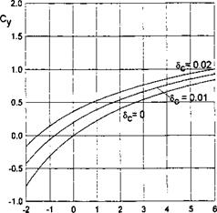
where в = в/h, в is the angle of pitch, Ej = O(h) and fj(x) = 0(1) are parameters and functions characterizing deformation of the lower surface of the wing, Ej — £j/h = 0(1), 0 = 0(1), and Ej = 0(1). For example, if the lower surface of the wing has the form of a parabolic arc with a relative curvature of 5C, the corresponding contribution to the sum in formula (4.70) is equal to 45cx(l — x), where Sc = Sc/h. It follows from (4.68)-(4.70) that the channel flow velocity v(x) and, consequently, the other aerodynamic characteristics (pressure coefficient, forces, and moment) should depend upon G and the set of parameters 0,5f, Ej, (j = 1,…, N).
The lift and moment coefficients, as well as the abscissa of the center of pressure, are represented by the expressions
|
xp ~ p * |
|
|
|
|
As discussed previously, the leakage of the flow from under the endplates leads to generation of vorticity and, consequently, induced drag. For a steady lifting flow in the extreme ground effect, it follows from (4.64) that
We consider some analytical solutions of the main equation for steady flow. In some practically interesting cases, equation (4.65) with condition (4.67) can be integrated in closed form.
Let the effective gap under endplates 5ep be constant chordwise. Note that, if one defines the effective gap as a geometric gap under the endplate, the above assumption implies chordwise uniformity of the latter. If one introduces the outflow contraction model, the effective gap would depend on the ratio of the geometric gap to the local ground clearance h*(x), and, consequently, would vary chordwise even when the geometric gap is constant. However, for small magnitudes of the relative geometric gap, the effective (contracted) gap can be considered practically constant for a given setting of the endplate (or flap) with respect to the ground plane. We set A = 1 in equation (4.68), so that <5ep(x) = = const.
We consider some closed form results for the flow with leakage.
We turn to consideration of the simplest case of a flat rectangular wing at zero pitch angle в = 0 with endplates and a rear flap. In this case the lift of the wing is due to deflection of the flap (5f ф 0). Because both the local ground clearance and the distance from the tips of endplates to the ground are constant chordwise (h*(x) = 1 and Sep(x) = <^p)> equation (4.68) takes the form л
+ Gy/l-v(x)2 = 0. (4.75)
dx
Note that both signum function in front of the square root and the absolute value sign under the square root were omitted because in this case one expects no suction under the wing, so that v(x) < 1.
The integral of (4.75), complying with boundary condition (4.67), is given
by _
v(x) = — sin (Gx + arcsincJf). (4-76)
The distribution of the pressure coefficient p(x) along the channel under the wing can be obtained by the formula
The lift and moment (with respect to the trailing edge) are given by the expressions
With reference to (4.74), the induced drag coefficient may be found as
Cx. = /і j[l – sin(G + arcsinJf)]2 – (1 – 5f)2 j, G = -—jp. (4.80)
As seen from these formulas, in the example under consideration the aerodynamic characteristics of the wing depend on only two parameters, namely G and Jf. At the same time, the original problem contained four parameters, including the relative ground clearance h, the aspect ratio Л, the effective gap under the endplates 5°p and the effective gap under the flap 5f. Thus, in this example, the use of similarity criteria reduces the number of independent parameters of the problem twofold! Generally, for a uniform distribution of the gap under the endplates along the chord, the number of parameters that characterize the flow problem for h —> 0 will be n — 2, where n is the initial number of parameters.
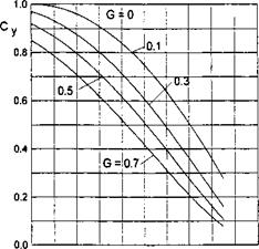
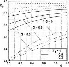
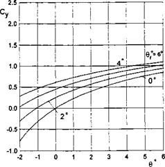
The lift coefficient Cy and the abscissa of the center of pressure xp = mz/Cy versus the similarity criteria 5f and G = 2£°p/A/i are plotted in Figs. 4.8 and 4.9. Plotted in Fig. 4.10 against the similarity parameter G for different flap settings is the induced drag coefficient CXi related to h.
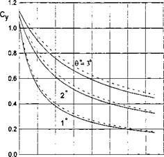
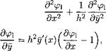
Another integrable case is that of a flat plate at pitch angle 0 with endplates at a constant gap <5ep(a;) = 5ep and a short rear flap. In this case, the ground clearance function h*(x) = 1 + Ox, 9 = в/h, and equation (4.68) yields
 (4.81)
Rewriting (4.81) as
![]() (1 + Ox) -—h 9v(x) + G y/ — v(x)2 = 0, ax
(1 + Ox) -—h 9v(x) + G y/ — v(x)2 = 0, ax
we can separate the variables in the following way:
![]()
|
 |
0.0 0.2 0.4 0.6 0.8 – 1.0
Sf
Fig. 4.9. The abscissa of the center of pressure of a wing with endplates at zero pitch angle versus the trailing edge flap setting for different magnitudes of similarity criterion G = 2<5eP/A/i.
Introducing the alternative similarity parameter Gq,
we obtain from (4.84)
|
G* exp ^ |
 |
|
It follows from the preceding calculations that the solution of the basic equation is dependent on a pair of parameters, in particular, G = 25°p/A/i and 0 = 0/h, or on an alternative pair of parameters Gq — 2J°p/A0 and 0. It is worthwhile mentioning that parameter G#, discussed herein, is identical to parameter H, introduced by Gallington et al. [61]. The integral of equation (4.85) can be obtained in closed form. The result in the form of an implicit relationship x = x(v) can be written as
|
C* = exp So, finally, Ox — exp where L(v, Go,8f) = In |
 |
Applying the boundary condition (4.67), we can determine the constant C* as
|
Fig. 4.11. The lift coefficient of a wing with endplates versus pitch angle for different magnitudes of similarity criterion G = 25°p/h and flap settings. |
|
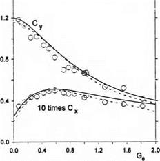
Fig. 4.12. The lift and drag coefficients of a rectangular wing with endplates versus parameter G$ = 25^р/Х0: theory and experiment (Л = 0.5; circles: experiment [61]; solid lines: present theory; dashed lines: G-theory). |
The structure of (4.88) shows that in the example under discussion the solution (span-averaged velocity and pressure coefficient) depends on a new independent variable x = 6x and the similarity criteria Gq and <Sf, i. e.,
v = v{xi, Ge,8{), p = p(x1,Ge,6{).
![Подпись: Fig. 4.13. The lift-to-drag ratio of rectangular wings with endplates: theory and experiment (empty circles: experiment for Л = 2/3 [61]; black circles: experiment for Л = 0.5 [61]; solid lines: present theory; dashed lines: G-theory).](/img/3131/image411.gif) |
The coefficients of lift, longitudinal moment (with respect to the trailing edge) and the abscissa of the center of pressure are calculated by the formulas (4.71)-(4.73).
The flow model, described by equation (4.82) with boundary condition (4.67), contains as a particular case the previously mentioned G-theory, proposed by Gallington et al. [61]. The latter theory, based on elementary continuity considerations, implies that the pressure does not vary along the chord of the wing.
To retrieve the governing equation of the G-theory from equation (4.82), suppose that a solution of this equation exists, for which the span-averaged velocity (pressure) is constant along the chord, i. e., v(x) = const. = v. Then, for a flat rectangular wing with a constant gap under the tips of the endplates and pitch angle 0, equation (4.82) can be rewritten as
_____________________ 25°
v + GgV l-v2 = 0, = (4.89)
Ли
Equation (4.89) can be easily solved with respect to v to give
It follows from (4.90) that the both pressure and lift coefficients in the G- theory depend only on parameter G^, i. e., are defined in terms of a certain combination of the gap under the endplates, the aspect ratio and the adjusted
pitch angle of the wing. On the other hand, (4.89) provides a simple tool for designing a ram wing vehicle for a given pressure in the channel At the same time, the assumption of constant v together with prescribed boundary condition (4.67) necessitates the following equalities:
indicating that the rear flap should be “tuned up” to ensure the prescribed pressure in dynamic air cushion. These relationships show, in particular, that an increase in the design ground clearance for the same magnitude of loading should be followed by an opening of the gap.
The foregoing approach to determining the aerodynamic characteristics of rectangular wings with endplates in the extreme ground effect remains valid for foils with local suction. One example of such a foil is illustrated in Fig. 4.14, which shows the lift coefficient versus the generalized gap parameter G for a foil with a parabolic lower surface and zero pitch angle. Other examples of calculation of the aerodynamic parameters of foils with local suction are discussed in the next section in connection with the problem of the static stability of longitudinal motion.
Now, we turn to the case when the generalized gap parameter is equal to zero, i. e., G = 0. Note that this can occur either for zero clearance under the tips of the endplates 5ep = 1 or when the wing has an infinite aspect ratio (A -> oo). For <jf = 0, the latter case corresponds to the description of the order of 0(1) of the two-dimensional flow problem for a foil moving close to the ground, as discussed in paragraph 4.1.
 o. o
o. o
Су
-0.2 -0.4 -0.6 -0.8 -1.0
In this case, the equations (4.65) and (4.67) can be rewritten as
![]() h*(x)v(x) = 0, v(0) = —5f.
h*(x)v(x) = 0, v(0) = —5f.
ax L J
|
h*(x) |
|
h*(x)- |
|
h*2(x) |
The solution of problem (4.90) is elementary,
Here are some simple analytical expressions for Cy and mz for some particular cases:
|
-p – 2* Flat plate without a flap <5f = 1 at a given incidence 6: c =J – y l + e’ |
Flat plate with a rigid flap at zero pitch:
Note that for small perturbations these formulas yield corresponding expressions of the linear theory, whereas for moderate and large perturbations, they reflect the inherent nonlinearity of the aerodynamics of the extreme ground effect.
• Flat plate at pitch angle 9 with a rigid flap
Employing formula (4.63), it is easy to find the suction force coefficient as
Cs = h(l + 9)(l-j^y. (4.97)
Because for G = 0 (no gap under the endplates or an infinite aspect ratio) there is no lateral leakage, the overall drag force acting on the wing in potential flow should be zero. Taking into consideration the magnitude of the pressure drag coefficient for this case,
CXp = – Cye + CXp( =-he(l-^L)-h(l-8f)2, (4.98)
we obtain the following result:
CXi = CXp + Cs
= – M(l – – Ц1 – 6f)2 + /1(1 + 0)(1 – y^)2 = 0, (4.99)
which confirms the correctness of the determination of the suction force coefficient.
• Flat plate with incidence and a jet flap at the trailing edge:
In this case, the corresponding effective gap under the jet flap entering the problem can be determined from local analysis of the flow near the jet flap (see section 6) as
where Cj is a coefficient of the total momentum of the jet and r is the angle of blowing.
Substituting with <5jf in expressions (4.96), as given by (4.100), we obtain the following formulas for the aerodynamic coefficients of a a foil with a jet flap at the trailing edge:
![]()
а – т^сдщ2
The induced drag coefficient of a jet-flapped rectangular wing with end – plates at pitch angle 9 can be found from (4.74) with Sf replaced with the effective gap under the jet flap 5^; see (4.100). In the particular case of zero incidence, we obtain the following expression:
CXi = /ij[l – sin(G + arcsin5jf)]2 – (1 -^f)2j, <$jf = Ty 7^- (4.ЮЗ)
It is interesting that introduction of the effective gap under the jet flap <5jf renders identical the structure of the formulas for predicting the aerodynamic coefficients in the cases of a wing with a rigid flap and wing with a jet flap.
The general formulation of the flow problem for a wing in close proximity to the ground, presented in section 2, covers a wide range of aerodynamic modes of the operation of ground-effect machines for h <C 1.
In what follows, attention will be attached to the particular case of a flying wing with endplates in the extreme ground effect, when relative gaps under the tips of the endplates are small.
In this case, the leakage of air from under the lifting surface is hampered, resulting in a considerable improvement in performance. Whereas for h —> 0, the description of the flow under the wing is independent of the vertical coordinate (see section 2), for vanishing gaps between the endplates and the ground, the channel flow becomes almost one-dimensional. Accounting for the fact that the upper flow contribution can be shown to be of the order of 0(/i), one can conclude that for a lifting system in the extreme ground effect and small clearances under the tips of the endplates, the dominant nature of the flow is one-dimensional.
A simple one-dimensional model of channel flow with leakage was first introduced by Gallington et al. and will be called the G-theory herein. It was assumed therein that the flow parameters are independent of the chordwise coordinate and that the leaking flow escapes into the external region of atmospheric pressure. To account for the intensive generation of vortex sheets emanating from wing’s side edges, the G-theory implies that separation occurs at the tips of the endplates. Though simple, the G-theory of channel flow agrees qualitatively with experiments and provides useful similarity criteria, convenient from the viewpoint of processing test data and designing vehicles. As pointed out by Ando [62], Gallington’s flow model does not exhibit the infinite (logarithmic) increase of velocity at the gap encountered in other flow models. However, due to the assumption that the flow parameters (velocity, pressure) are not dependent on the chordwise coordinate, the G-theory cannot be used to predict the moments and characteristics of longitudinal stability. Secondly, the model under discussion does not account for edge effects, thus preventing determination of such characteristics as, for example, the suction force at the leading edge.
In what follows, an extended one-dimensional flow model is introduced for a wing with small gaps under the endplates; see Rozhdestvensky [63]. This new model accounts for chordwise variation of the channel flow velocity and incorporates unsteady effects. It can be used for evaluating the efficiency and stability of a simple flying wing configuration in the extreme ground effect. It also produces formulas, useful for processing of experimental data,
identification of parameters of the lifting system, and eventually, can serve as a tool of conceptual and preliminary design.
Below, follows a derivation of the governing equation for unsteady flow past a lifting surface with small gaps between the tips of the endplates and the ground.
|
/l*(x, 2, t) |
|
h*(x, z, t) |
We recall a general limiting problem, formulated earlier for the velocity potential of the absolute motion of a fluid when h —> 0; see paragraph 2.7. This problem is governed by the quasi-harmonic equation
which can be obtained from (2.115) by replacing the absolute potential ірг with the potential of relative motion ф and h* = h*/h0 with h* = h*(x, z,t). As previously, the latter quantity represents the local clearance under the wing. All functions and parameters are rendered nondimensional by using the root chord C0 and a characteristic velocity U0.
Restricting the analysis to a rectangular wing (see Fig. 4.7), we average equation (4.46) spanwise by using the integral operator
where Л is the aspect ratio of the wing.
Assume additionally that the clearance distribution function depends only on the longitudinal coordinate and time, i. e., h* = h*{x, t). Then

 (4.47)
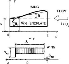 Fig. 4.7. A rectangular wing with endplates in the extreme ground effect.
|
h*(x, t) |
|
dh*(x, t) dt ’ (4.48) |
and, introducing the spanwise averaged potential ф, we obtain
|
h*(x, t) |
Equation (4.48) includes a function дф(х,±/2,і)/дг that represents the transversal velocity component under the wing in the close vicinity of the endplate. For a practical case of symmetrical leakage, when dф/dx(x1 Л/2) = —dф/dz(x, — Л/2), we obtain from (4.48)
We relate the velocity vep of transversal leakage to the spanwise averaged longitudinal velocity d(t>/dx(x, t), assuming that the perturbed pressure outside of the endplate is equal to zero. Let Sep(x, t) represent an effective gap under the endplate (nondimensionalized with respect to the chord). Then the velocity vep of the leakage is given by
vep(x, t) = h*{x, t)^(x, t, ^)/8ep(x, t), (4.50)
and the corresponding dynamic condition just outside of the endplate takes the form
 p(x, t) = U2(t) -vip(x, t) –
|
3ep(%> 0 h*(x, t) |
where U(t) is a function, describing the time variation of the speed of the vehicle cruising. It follows from (4.50) and (4.51) that
= signp(x, t)y/p(x, t), (4.52)
|
h*{ |
|
dh*(x, t) dt |
where p(x, t) is the span-averaged pressure coefficient under the wing. Taking into account (4.51), equation (4.49) takes the form
Equation (4.53) is a one-dimensional description of the flow in a highly contracted channel under the lifting surface with endplates that accounts for the lateral leakage of air through the gaps under the endplates. Essentially, such a description corresponds to a small ground clearance and small (with respect to the characteristic height h above the
ground) gaps under the tips of the endplates. Note that the plus in front of the square root term in (4.53) corresponds to the outward leakage, whereas the minus corresponds to the inward leakage. As accounted for by the signum function in (4.53), the direction of leakage depends on whether at a given moment and for a given station x along the chord, the pressure coefficient under the wing is positive (pressure) or negative (suction). In the former case, the leaking flow is directed from under the wing into the external area, whereas in the latter case, it is directed inward.
Note that the definition of the effective gap Sep under endplate depends on the choice of the flow model of the leakage from under the endplate (or flap).[21]
Two boundary conditions necessary to solve equation (4.53) ought to be determined by smooth blending (asymptotic matching) of the channel flow with local flows near the leading and trailing edges. It has been shown in section 2 by using local flow solutions that for the extreme ground effect case (h 1), an appropriate boundary condition at x = 1 (leading edge), has the form
0(1,0 = 0. (4.54)
From the physical viewpoint condition (4.54) signifies that in the extreme ground effect, the vorticity in the channel under the wing is accumulated (due to the development of the boundary layer), counting from the leading edge.
The boundary condition at x = 0 can be obtained from the requirement of pressure continuity at the trailing edge and by using asymptotic estimates for h —> 0 of the pressure coefficient above the wing p = 0(h) and in the channel beneath the wing p = 0(1). Introducing an effective gap 6f(t) under the trailing edge, we can write the corresponding dynamic condition as
p(x, t) = U2(t) – vj(t) -2^(0,t) =0, (4.55)
where Vf(t) is the velocity of the flow leaking out from under the trailing edge. This velocity is related to that of the channel flow in the immediate proximity of the trailing edge by the flow continuity relationship
g(°,<) = (4.56)
wherefrom taking into account (4.55), we deduce the second boundary condition for equation (4.53) at x = 0:
^(0,0 = -?rWyi^W-2g|. (4.57)
In addition to boundary conditions (4.54) and (4.57), an approprate initial condition should be imposed. For example,
![]() ^(*,0) = vo(®).
^(*,0) = vo(®).
The lift and moment (with respect to the trailing edge) coefficients can be calculated by using the formulas
![]() p(x, t)dx, mz = xp(x, t)dx,
p(x, t)dx, mz = xp(x, t)dx,
Jo
where the pressure coefficient is given by the expression
![]() p(x, t) = U2(t) –
p(x, t) = U2(t) –
On the basis of the solution of a one-dimensional unsteady nonlinear flow problem past a rectangular wing with endplates in the extreme ground effect, we can derive the induced drag coefficient. As previously in the general case, the induced drag is defined as the difference between the pressure drag in inviscid flow and the suction force acting upon the leading edge. Hence, the corresponding coefficient can be written as
C’xi — Cxp + cB,
where CXp is a drag coefficient due to the action of the normal aerodynamic loading in the longitudinal direction (ideal pressure drag) and Cs is the suction force coefficient. To obtain CXp, we project the spanwise averaged pressure forces, obtained within the present theory, onto the longitudinal direction. For a small rear flap, we can determine separate contributions of the wing CXpvr and of the flap CXp{ to the pressure drag of the lifting system. Accounting for the coordinate system adopted in this book, one can derive the following expression for CXpw:
Cxpv(t) = J p(x, t)cos(n, x)dx =-h0 J p(x, t)^dx, (4.59)
where y = y/h0, y = y(x, t) are the ordinates of the points on the lower surface of the wing, measured from the unperturbed position of the underlying surface. In the case of a flat wing, it follows from (4.59) that Cx = —Cy9.
The ideal pressure drag of the rear flap can be obtained by using the solution of Gurevich [138] for the drag of a wedge with streamline separation. Renormalizing the expression of the pressure drag coefficient obtained by Gurevich with respect to the velocity on the (jet) free boundary and the area of the wing planform, we obtain a simple formula for the pressure drag
coefficient of a rigid flap in separated flow [22]
CXp{(t) = h0[l – (t)]2, = S{/h. (4.60)
Now, we can turn to the derivation of the coefficient of the suction force acting upon the leading edge. This force presents an integrated effect of suction, occurring due to the large curvature of streamlines in the vicinity of the leading edge. In principle, the suction force contribution should be determined by integrating the projection of the local suction force over the contour of the leading edge, but it is rather difficult to single out this force numerically. At the same time, calculations show that, as the foil becomes thinner, the local suction increases whereas the radius of the leading edge decreases. These two factors vary so that their product remains finite and almost constant up to the limiting case of zero foil thickness. That is why it is often assumed that the theoretical value of the suction force determined at the leading edge of zero thickness can be utilized for practical rounded edges with a finite radius of curvature. By using formula (2.39), the asymptotics of the flow velocity of the relative motion at the points of the leading edge of the wing in the extreme ground effect can be written as
~J~T = cli + О {hi), (4.61)
where (pae is determined by formula (2.42). Matching (4.61) with the channel flow velocity v(x, t) and accounting for the asymptotics of (2.47) leads to the following expression for a\
a = h*(l, t)[U(t) +i(l,£)]. (4.62)
Substituting (4.62) in formula (2.113) to determine the suction force on a wing in the extreme ground effect, we obtain
= ЬотЙ^г = h0h*(l, t)[U(t) + v(l, t)}2. (4.63)
ft (M)
Eventually, the induced drag coefficient can be written as
cxi(t) = h0{h*(l, t)[l + V(l, t)}2 – da:- [1 – 5f(*)]2}. (4.64)
Examples of calculation of the induced drag coefficient for particular cases will be presented later.
Thus, a one-dimensional nonlinear formulation has been found for the aerodynamics of the longitudinal motion of a rectangular flying wing with
endplates in the extreme ground effect. This formulation includes equation (4.53), boundary conditions (4.54) and (4.57), and initial condition (4.58). This mathematical model accounts for unsteady effects, which can be caused by motions of the wing as a rigid or deformable lifting body, the action of control devices and wind-wave perturbations. Though sufficiently simple, it retains the inherent nonlinearity of the aerodynamics of the extreme ground effect with respect to the geometry and kinematics of the lifting system. The common sense basis of simplifying the flow model consists of the observation that when the endplate tip clearances are very small, the channel flow, already ’’squeezed ” vertically for h —> 0, becomes almost one-dimensional.
This formulation can be used to evaluate the aerodynamic characteristics and preliminary design of a flying wing configuration for both cruise and power augmentation performance. Note that equation (4.53) describes the main contribution to the aerodynamics of the wing-in-ground-effect vehicle, namely, that of the channel under the main lifting surface. The contribution of the upper surface of the wing can be added, using the general asymptotic approach presented in section 2. Alternatively, due to experimental evidence that, in close proximity to the ground, the upper surface pressure distribution varies insignificantly with variation of h, the upper surface characteristics can be, with a certain degree of approximation, borrowed from the unbounded fluid case.
4.1 A Curved Thick Foil
in a Two-Dimensional Ground Effect
First, we consider an example of a flow problem for a moderately curved thin foil in the ground effect,1 and then present some results for thick foils. Essentially, as discussed at length in section 2, the procedure for the solution uses the assumption that, for h <C 1 and є = 0(h), nonlinear effects exhibit themselves mainly in the narrow channel under the foil. The foil and the corresponding coordinate system are shown in Fig. 4.1.
 |
у
 |
Coordinate System for a Foil in Ground Effect
The term “moderately curved” implies that the distances of points on the foil contour from the horizontal line у — h are of the order of О(h).
K. V. Rozhdestvensky, Aerodynamics of a Lifting System in Extreme Ground Effect © Springer-Verlag Berlin Heidelberg 2000
|
The complete problem for the perturbation velocity potential has the form
|
The solution of the upper flow problem can be written in a straightforward manner. The velocity potential at points on the upper surface of the foil is defined by the expression
¥>ui = тр Ц1 – re)–/ 3/s(£>e)ln(z-£)d£. (4-Ю)
І7Г 7Г Jq
Asymptotic expansions of cpUl near the edges are obtained in the following form:
• Near the leading edge,
![]()
![]() Ql і,1 -!(л і, Ai. ^2
Ql і,1 -!(л і, Ai. ^2
<^Ul – — ІПІ/+ —2/s(l) ^lni/ + і/— + —,
Z7T 7Г 7Г 7Г
![]() Jo
Jo
M = ~f ln(l ~ 0
Jo
• Near the trailing edge,
1 В В
(pUi ~-y’s(0)va. v+ v———- -, v-> 0, v = – x, (4.11)
7Г 7Г 7Г
si = y–y’s(Q)-Jo ШО-уК0)}-^’ B2 = ~J0 ^(£)ln£d£- (4-12)
• The channel flow region Д,
The nonlinearity of the ground effect exhibits itself mainly in Д. After introduction of a stretched vertical coordinate у — yjh into the full problem, we obtain the following channel flow problem with respect to the perturbation potential (f:
 0; (4.13)
У = У*(£,х); (4.14)
Note that in the upper flow limit, the influence of the condition at infinity is lost.
We seek <p as an expansion
щ = <рї + h2tf* + 0(h3), (<РІ<рГ) = 0(1), (4.16)
where
![]() <Pi = <Ph + h]n-<ph +h<pi.
<Pi = <Ph + h]n-<ph +h<pi.
Substituting (4.16) in (4.13)—(4.15), we obtain
(4.18)
i. e., for h <C 1 and є = 0(1), the flow under the foil is “almost” onedimensional2 and is governed by the elementary equation (4.19). The solution of this equation can be derived in the form
<^i — x + C —C2, (4.20)
J Vs
where the constants C and C2 are found from the boundary conditions at the ends of the interval x Є [0,1]. Because the function ys can be represented as
N
ys(S, x) = 1 + ‘^T/£jfj(x), (4.21)
3 = 1
the function (p* depends nonlinearly on є.
• The edge regions De
Near the edges of the foil, we introduce isotropic stretching of coordinates
As previously discussed in a more general case, the distances of the points on the foil from the horizontal line passing through the trailing edge are of the order of 0(h). So, with an asymptotic error of 0(/i2), the flow tangency condition can be imposed on the lines ys = jjf(l) (near the leading edge) and Vs = 2/s(0) (near the trailing edge). This simplification enables us to formally utilize the edge flow solutions obtained within the linear theory.
|
<Pie = O’lhpae + CL2h[18](pbe + azh2ys(l)v + a4/i, |
The leading edge flow velocity potential
v = v/ys{]), and /e is determined through the equation
![]() пй = 1- exp /e + /e.
пй = 1- exp /e + /e.
Near the trailing edge,
<Pte = hh2(fbe + b2h2v + b3h, i> = v – (4.25)
The solution for ірье is found from (4.23), substituting j/s(l) and y'(l) by 1 and y((0), respectively.
Matching gives the following results:
|
dip* |
The boundary conditions to determine the constants of the solution (4.20) were found in the form
The lift coefficient is obtained by integrating the composite expressions for the pressure coefficients on the upper and the lower surfaces of the foil, i. e.,
where the upper and lower surface contributions to the pressure coefficients are defined by the formulas
We consider some examples:
|
2/10(2 + 0), + —(IT?)1" |
• Flat plate (ys = 1 + Ox, 6 = 6/h, 0 – pitch angle)
For vanishing 0 —» 0, formula (4.36) yields the linear result of Widnall and Barrows [40]; see formula (3.42). For the extreme ground effect (first term),
cy-Cl = TTe – (437)
It follows from (4.37) that
for 0 —^ 0, Cy ~ 0; for 0 —» oo, Cy ~ 1.
These results indicate that when both incidence and ground clearance tend to zero, permutation of the limits (6/h —>• 0 or 6/h —> oo) yields different results.
The limit 6/h oo implies that the trailing edge of the foil touches the ground before the pitch angle becomes equal to zero. It can be concluded from observation of (4.37) that, if one measures the ground clearance from the leading rather than the trailing edge, i. e.,
hie = h + 0, (4.38)
that is, the lift coefficient of a flat plate found from the nonlinear solution becomes linear in 0.[19] This conclusion holds exactly to the lowest order.
Figure 4.2 shows some results, obtained by using formula (4.36), in comparison with calculated data of Grebeshov et al. [137].
|
02 + 45c(2 + 0) 16Sc |
The next example is related to a parabolic foil, for which ys = 1 + Ox + 4Sc x(l — x),Sc = S/h, 6 = 6/h,
Qc — j (6 + 45c)2 + 16<5C,
C2 = —[0 + (0 + 45c)(l — Ci)],
7Г
![]()
|
[*(ln ~ ~ ~) + 4SC + [(в + 45c) In 7Г – 45c](l – C-h
For в —» 0 and Sc 0 we obtain the linear result (3.43).
 Another example is a flat plate with a flap at the trailing edge. For this case, ys = 1 + (0 + 5f) x, 0 < x < bf4 and ys = 1 + Sfbf + Ox, bf < x < 1, where bf is the chord of the flap and 5f represents the flap deflection angle, Si = Sf/h, _ _
(4.41)
С2 = -[6Ь{ + в + (в + 6{)(1-С1}-,
7Г
—5f [(1 — bf) ln(l — bf) + bf In bf]
+[5f(lnbf – bf + l) + (0 + 5f)ІП7Г](1 – C!)|.
If в = 0 and 5f -4- 0, expression (4.41) yields the corresponding linear results; see formula (3.47). Some of the calculated results for the lift force coefficient of a moderately curved foil-in-ground effect are presented in Figs. 4.3 and 4.4.
|
Є" Fig. 4.3. The lift coefficient of a parabolic foil-in-ground effect versus pitch angle and relative curvature, h = 0.1. |
|
Fig. 4.4. The lift coefficient of a flat foil with a flap in the ground effect versus pitch angle and flap deflection angle, h = 0.05, 6f = 0.3. |
In what follows, some results are presented for a moderately thick foil[20] in a steady ground effect. For a foil with maximum relative thickness St, the ordinates of the upper and lower surfaces can be defined as
yu(x) = h + 0x + 6tfu(x), 2/i(ж) = h + 0x – Stf(x),
where 9 is the angle of pitch, and functions fu(x) and f(x) describe the positions of the upper and lower surfaces of the foil with respect to the chord line.
The lift coefficient is found in the form
![]()
 |
Су — C + C^/iln — + C3/1,
С2 = -[Уи(1)-1 + У,»(0)(1-С1)];
Сз — — v42+ai 1-ai+ln _ +(1—Cyi)[j/u(0)(ln7T—l)+j/{(0)—Бі]|;
l = ^, b2-a2 = J’u(o bijld
For the limiting case of zero clearance (h — 0), one can deduce from (4.42) the formula that corresponds to the situation when the trailing edge of the foil slides along a flat ground surface:
In the particular case of a flat plate for which yu = y = 1 + Ox, 0 = 6/h, the third term of (4.43), vanishes, and the formula is reduced to
Cy = 1 + H£ln£. (4.44)
Formula (4.44) is in satisfactory agreement with the exact theory of Tomotika and Imai [27] and Datwyler [28] up to angles of pitch of 5-6°. We can extend the range of validity of (4.44) by constructing an asymptotically equivalent expression
|
/Vu(0 hh-id*. К Jo £ |
![]()
![]()
 |
7Г
7Г 0 1 — 201п(7г/0)/7г’ which is in agreement with the exact theory up to angles 12-15°.
Consider a moderately thick foil with a flat lower surface and the upper surface in the form of a parabolic arc. In this case y = 1 + Ox, yu = 1 + Ox + 4Stx(l — x), St = St/h, where <St is the maximum relative thickness. The lift coefficient is found in the form
Cy – CyplM + (в + In £ – l), (4.45)
where Cyplate is the lift coefficient of a flat plate, as given by (4.36). If the trailing edge of the foil touches the ground, 0 = oo, and it follows from (4.45) that
~ і 20 7Г 8St
Cy — 1 H—- In — H—– .
7Г в 7Г
For a wing of finite aspect ratio, all derivations can be carried out to the order of 0(h), which is practically enough to provide reliable information for relative ground clearances up to 0.1-0.15. However, here the analysis will be restricted to the least cumbersome (from the viewpoint of the algebra involved) case of the extreme ground effect. Moreover, the concrete case of an oscillating flat plate with a rectangular planform will be considered. Due to linearization, the effects of camber can be superimposed.
Let a finite wing perform heave oscillations with the following description of its instantaneous position with respect to the ground:
different magnitudes of the Strouhal number. For A -> oo, formulas (3.101) and (3.102) yield results of the corresponding unsteady two-dimensional flow problem. For A —> 0, the following expressions are obtained:
|
|
Consider a thin foil advancing near the ground with a constant speed U0 and simultaneously performing small vertical motions (heave, pitch or deformations). An unsteady wake, consisting of the shed vorticity, is formed behind the foil in the process of such a motion. According to the general scheme discussed previously, the channel flow in this case will be described by the following relationships:
Щ (x, t) = tp*(x, t) + 0(h2),
where
4> – 4> (x, 0 = 4>h (x,0 + h In (x, t) + h(f3 (ж, t),
as is a function of the order of О(є//і), characterizing the vertical component of the flow velocity given on the foil.
The solution of equation (3.85) can be written in the form

![]() (3.86)
(3.86)
where C(t) and C^t) are the functions of time to be determined with the help of the boundary conditions for the channel flow potential at the leading and trailing edges.
|
(0 ,**)> |
|
dt*2 |
The lowest order induced unsteady downwash in the wake can be determined by using the formula
where t* = t + x. In the case of harmonic motions,
(0, t*) = acoskt* + bsin/cf*, aWl = — к2(рг (0, £*),
where a and b are constants determined in the course of solving the lowest order problem, к = loC0/U0 is the Strouhal number, and и is the circular frequency of the unsteady process.
In the upper flow, the corresponding asymptotic expansion for the velocity potential has the form
<Pu = htpUl + o(/i2 In i).
Solution (рг is constructed by distributing along a semi axis x < 1 sources (sinks) whose strength is equal to the doubled local downwash, which is
given on the foil and determined in the wake. At the leading edge, we place an admissible point source (sink) solution that does not violate the flow tangency conditions either on the foil or in the wake. Thus, at points on the upper surfaces of the foil and the wake
= 2тг ІП^ ~ + 2^ / q^ ln(X ~ ® d^’ (3-87)
where
t = і -2as(x, t), 0 < x < 1;
^ — 2aWl(x, t), — oo < x < 0.
Note that the strength of the point source (sink) at the leading edge has to be determined by matching. Note that when calculating (pUl with the help of (3.87), the following integrals are encountered:
These integrals are divergent in the conventional sense. Nonetheless, they can be calculated in a generalized (Abel-Poisson) sense; see Fikhtengoltz [135].
poo
I — lim / exp(—<5£) cos k( In £
 |
|
Jo
where 7 ~ 0.5772 – the Euler constant.
From a physical viewpoint, the generalized integration means that we consider slowly amplifying oscillations, turning in the limit into oscillations with constant amplitude. An analogous approach was used by Theodorsen in calculating integrals of the type
in the work on harmonic oscillations of a thin foil in an unbounded flow. Taking into account (3.88) and (3.89), the expression for <pUl can be rewritten as
|
|
|
Q, n = – ln(l-z |
|
<Xs(Z, t) ln(z-0 d£ |
к
+ — [(aG і + bG2) cos kt + (bGi — aG2) sin fcfc],
7Г
where
G—L cos kx + M sin fcx, G2 = L sin kx — M cos fcx;
L = si(fcx) — sin kx In x, M = 2 In fc + cos kx In x — ci(fcx).
Functions si(fcx) and ci(fcx) are integral sine and cosine, defined by the expressions
To match, one needs to know the asymptotic expansions of (pUl near the edges. These were found in the form
• Near the leading edge (у — x — 1 —> 0)
Q, , <*s(M) , , Axv A2
ipu, – х-шьЧ————– V in v——– 1——- 1- 0(v )
27Г 7Г 7Г 7Г
A2 = – f as(£,t)n(l-(;) d£+k[(aGn+bG2i) coskt+(bGn-aG2i) sinkt], Jo
where Gn = Gi(l) and G21 = G2(l).
Near the trailing edge (v = —x —* 0),
 V? U;
V? U;
(o! Uw) —
■Bi = ^Q-as(0,t)- f [as(£, i) — as(0, i)] ^ + fc{[a(fcG2o — 1) — bfcGio] cos kt
+ [6(fcG2o — 1) + afcGio] sin kt}]
B2 — — o;s(£, 0 In £ d£ + fc[(aGio + bG2o) cos kt + (bGw — UG20) sin kt],
Jo
Glo = G1(0) = ~ G2o = G2{0) –
The following results can be obtained from matching the solutions determined in the upper, channel, and edge regions.
Constants of the local solution at the leading edge (x = 1):
![]() 1
1
а і
a3 = ^ Ai+ «s(l, t) (l – In ^ , a4 = і (a2 – оц In ^). • Constants of the local solution near the trailing edge (x = 0):
![]() £i + <auw)(i-ln0], b+ = ^B2.
£i + <auw)(i-ln0], b+ = ^B2.
Application of the Kutta-Zhukovsky condition at the trailing edge (v — —x/h = 0) gives a relationship between, fcj" and bj, 63":
![]() db3 , dbt lr / 7r
db3 , dbt lr / 7r
b2+~dT~b2 + ^-n[Bl + M1~lnh) +
Boundary conditions for the equation (3.85):
At the leading edge,
¥>l(l,0 = ^ m — «1 (1+ In ^)
At the trailing edge (x = 0),
 As a result of matching, additional information was obtained that provides uniqueness of the asymptotic solutions, determined in different regions of the flow. Forming uniformly valid (additive) composite expressions for the pressure coefficient on the upper p+ and the lower p~ surfaces of the foil and integrating these expressions, we obtain formulas for the lift and moment coefficients
where

dx dt / V dx dt 1
As a first example, consider heave oscillations of a flat plate, for which instantaneous positions with respect to the ground are described by the equation
ys = h + h0 sin kt,
whereas the vertical downwash on a plate
The lift coefficient was obtained with an asymptotic error of the order of О(h2) in the following form:
![]() Cy = hC* + hC$,
Cy = hC* + hC$,

![]()
h 1 2(1 + k2)2 + 2 – k2 7ГІП h (1 + A;2)2
h 2-k2 h l(l-k2)(2 + k2) y 6(1 + A:2) + 7Г ft (1 + A;2)2
![]() h f 2(1 + 1п7г) — 2k2 1п7г(2 + к2) — k2[2kGn + (к2 — 1)G2i]
h f 2(1 + 1п7г) — 2k2 1п7г(2 + к2) — k2[2kGn + (к2 — 1)G2i]
+^l 2(1 +A:2)2
where
Gїї = Gi(l) = si(fc) cos к + [2 In к — ci(fc)] sin fc;
G21 = G2(l) = si(fc) sin fc — [2 In fc — ci(fc)] cos fc.
The solution obtained here is valid for a small clearance (/i < 1) and a large range of Strouhal numbers fc C l//i. Some calculated results based on formulas (3.91) and (3.92) are presented in Figs. 3.14 and 3.15.
 |
On the same graphs are plotted the numerical results of Efremov [104], obtained by the discrete vortex method for h = 0.1. In a similar manner
it is possible to derive formulas for the aerodynamic derivatives for pitch oscillations around a point with abscissa a0 and oscillations of a flap around a hinge point. For briefness, the corresponding expressions for aerodynamic coefficients will be written only for the extreme ground effect (leading order):
• For pitch oscillations,
![]()
 |
Cy = 901 + 90°,
• For oscillations of the flap,
Су = efCf + efCey<, (3.94)
hCef = 2bt – bj + k[1 – bf + bf2(6 – 4)/12] – k^jl + 3bf)/6 | 1
y 1 + k2 hh
,, = h(2bf — 2bf/3 — 1) + (1 — bf/2) + 0(Ып 1
1 -(~ к гь
The solution obtained above for the general case of harmonic perturbations is valid both for oscillations of the foil as a solid body and for deformations of the foil.
To avoid cumbersome algebra, consideration will be confined in this section to the simplest case of the extreme ground effect for a wing with a straight trailing edge. In the steady flow problem, the velocity potential does not depend on time. Consequently, there are no unsteady free vortices in the wake, and the corresponding flow model is substantially simplified.
Recalling the formulas for induced downwash aw at the trailing edge, one should mention that to the lowest order of approximation aw ~ aWl, and downwash does not depend on the abscissa x of the point in the wake, i. e.,
aWl=h(^(0,Z). (3.57)
Therefore, if the wing is in steady motion and its relative clearance is small, then at all points of the wake with the same z coordinate, the downwash is “almost”[14] the same as that behind the trailing edge. This important circumstance allows writing formula (2.109) for determining the induced drag coefficient (accounting for suction force) for the case of small relative ground clearances in the following way:
= | J ¥>h (°, z) (0, z) dz, (3.58)
where, as earlier, S is the reference area of the wing related to the square of the root chord. In addition, the condition of optimality of the wing (in the extreme ground effect) can be written as a requirement that the downwash distribution at the trailing edge should be uniform in the spanwise direction.
As indicated in 3.1, in the case of the extreme ground effect, it is sufficient to solve the following problem:
• Boundary conditions:
(px =0 at the leading edge Zi,
pi = 2^^- =0 at the trailing edge. (3.60)
ox
For a flat wing, y[ = 6 = 6/h, where в is a pitch angle.
The lift and moment coefflcients can be calculated by using the formula
|
2 /**/2 Cy = — ірг (0, z) dz; & J-l/2 |
(3.61) |
|
2 f f d<ph (x, z) m* = sJJsx Эх dxd2- |
(3.62) |
|
We consider the example of a rectangular wing, for which the domain S is a rectangle 0 < x < 1, z < Л/2, where Л is the aspect ratio. At first, suppose that the wing is flat, so that the right-hand side of equation (3.59) is equal to 6 = 6/h, where в is the angle of pitch. We seek (px in the form |
|
|
oo <Ph = 9 ^2 Xn(x) cos qnz, n=0 |
(3.63) |
|
where qn = 7г(2п + 1)/A. Expression (3.63) should vanish for Noting that 4 ^ (-l)n cos qnz |
z = ±Л/2. |
|
and substituting (3.63) in Poisson equation (3.59), we obtain an ordinary differential equation for functions Xn(x) |
|
|
X" o2X – 4(“1)n Лп ЯпЛП — л • |
(3.64) |
A general solution of (3.64) can be sought in the form
sinh qnx cosh qnx 4(-l)n
Xn{x) = an————- + bn——————– V-/–
cosh Qji cosh q>n qn
Bearing in mind that the boundary conditions for the function фг at the ends of the interval 0 < x < 1 are
Vll(l,2)=0, -^-(0,^ = 0,
we obtain the conditions for the functions Xn(x) at the ends of the segment 0 < x < 1:
 *;(o)=o,
Finally, we find the following expression for the channel flow velocity potential:

 (—l)n /cosh(/nx
The distribution of aerodynamic loading to this order of approximation is

 |
д(рг 8в ^ (-l)n sinh</nx
A £ґ0 € cosh qn
In Fig. 3.8 examples are given of the distribution of parameter h(p) /в, which characterizes the aerodynamic loading, for rectangular wings of aspect ratios Л = 1 and Л = 3. The loading distributions have been calculated on the basis of the leading-order solution.
|
16 в tanh</n tanh(</n/2) ~h* |
The lift coefficient can be calculated as

![]()
![]() mz
mz
= 1C ~jf (ta–h-— + tanh tanh у – l). (3.66)
hX пҐоV 9" 2
The induced drag coefficient is
/-Ї h Ґ tr\9Vlwn u 802 ^ tanh2g„tanh2(g„/2)
C" = – A L, n(0’Z)^(0′ = £———— —•
As/i<l, the formulas obtained above are valid for practical arbitrary aspect ratio h « A < oo. The distance of the center of pressure from the leading edge is defined by the ratio xp = —mzjCy and mz and Cy are determined by (3.65) and (3.66).
If A —» oo, we obtain the formulas for a flat plate of an infinite aspect ratio:
Cy = -, mz = – —, Xp = Cx. = 0. (3.68)
It follows from (3.68) that for a plate of an infinite aspect ratio moving in very close proximity to the ground plane, the center of pressure is located at a distance one-third of the chord from the leading edge. Recall that in unbounded flow the center of pressure of a flat plate (A = oo) is located at one-fourth of the chord from the leading edge.[15]
For a small aspect ratio A —> 0, the general formulas yield the following results:
 (3.69)
16aA3
![]() /і7Г5 ’
/і7Г5 ’
96A
7Г°
 |
Some results of calculations of the aerodynamic coefficients of a rectangular wing versus the aspect ratio A are plotted in Fig. 3.9 with ten terms retained in the corresponding series. The terms of the series in expressions (3.65)-(3.67) decrease with the increment of n as 1/(2n + l)4. For not very large A, it is practically sufficient to retain one term, so that
 |
in Fig. 3.10, where the results of the present theory for h -> 0 are compared with those obtained by Belotserkovsky and Scripatch [130] for h = oo.
It is easy to determine the suction force coefficient Cs. Calculating the factor а і
4(9 ^ (-l)n,
— > —5— tanh qn cos qnz,
h ‘ qf.
n=о ™
and substituting this expression in formula (2.113) with є = в and /і* ~ h, we obtain the suction force coefficient in the form
![]() ^ _ г<вва2 _ 86,2 ^ tanh2 qn c’-c• 6
^ _ г<вва2 _ 86,2 ^ tanh2 qn c’-c• 6
n=0 71
In the limiting cases,
![]() for Л —^ 0, Cs —
for Л —^ 0, Cs —
Comparing the latter formula with (3.70), one can see that for the case of the extreme ground effect, quite similarly to the case of unbounded flow, realization of suction force on a wing of small aspect ratio reduces the induced drag by half.
Now, assume a spanwise distribution of the pitch angle of the wing sections in the form
e(z) = eo0(z).
The solution of problem (3.59)-(3.60) can be readily constructed in the following form:
|
во Sn (cosh qnx 7t(2n + 1) li = T У, “о (————– Г———- 1 cos qnz, qn =—————————– . h^oq[16]Kcos hqn J Л • Corresponding lift coefficient: oo £ • Induced drag coefficient: |
• Flow potential:
![]() n – в<> V" tanh2 tanh2(9„/2)
n – в<> V" tanh2 tanh2(9„/2)
x>~ h q3 ■
n=0
where 0n are determined by the following formula
2 fx/2
0n = – г 0(z) cos qnz dz.
л J-X/2
Following Widnall and Barrows [40], consider the case of the wing of semielliptic planform with a straight trailing edge. In this case the domain S is represented by a semiellipse with axes equal to 1 and I/2, where l is the relative span of the wing. Equation (3.59) and the boundary conditions (3.60) are satisfied, if the function <рг is sought in the form
<Ph = d(x2 + -Ji l)> (3.76)
where d is a constant. Substituting (3.76) in Poisson equation (3.59), in the case of a flat semielliptic wing,
![]() ві2
ві2
d~ 2h{l2+4Y
Taking into account that for vanishing ground clearances the distribution of circulation spanwise is equal to
m2 / 422
r{z) ^ -<Ph (o, z) – 2/l(/2 + 4) (! ~ ir)«
one can see that the loading of a semielliptic wing has a parabolic distribution spanwise.
The lift coefficient becomes
![]() m2
m2
v 37xh(l2 4- 4) ’
![]() For a semicircular wing (l = 2) the lift coefficient is two times less than for an semielliptic wing of an infinite aspect ratio (l oo). It is interesting that the limiting results for l —У oo do not coincide with those for the two-dimensional problem because in the limit the wing retains a semielliptic planform. In fact, in the two-dimensional case,
For a semicircular wing (l = 2) the lift coefficient is two times less than for an semielliptic wing of an infinite aspect ratio (l oo). It is interesting that the limiting results for l —У oo do not coincide with those for the two-dimensional problem because in the limit the wing retains a semielliptic planform. In fact, in the two-dimensional case,
Ci
whereas here for l —> oo,
It is worthwhile to mention that for a semielliptic wing in the extreme ground effect, the induced downwash in the wake is constant spanwise:
_ 46> :wi _ /2 + 4
![]() so that such a wing is optimal for any aspect ratio.[17] The induced drag coefficient is given by
so that such a wing is optimal for any aspect ratio.[17] The induced drag coefficient is given by
![]() 2вСу _ Cl _ 4/2 Л
2вСу _ Cl _ 4/2 Л
/2 + 4-7гАМ’ ^“Зт^А h~12h’
Calculating the factor a taking into account the equation of an ellipse, and using expression (2.113), one finds the suction force coefficient of a semielliptic wing in the form

![]() Cs = Cene92
Cs = Cene92
Use has been made of the formula A = 4Z/7г for the aspect ratio of a semielliptic wing. It is easy to check that expressions (3.78), (3.80) and (3.81) comply with the evident requirement Cx. = 9Cy — Cs for a flat wing. The influence of the aspect ratio on the lift coefficient and the induced drag coefficient for semielliptic flat wing in the extreme ground effect is illustrated in Fig. 3.11 in comparison with a rectangular wing.
Now, we can turn over to the case of a rectangular wing with a flap. Let the wing of aspect ratio A have a flap whose chord is equal to bf and deflection angle is 9f. The domain S bounded by the wing planform contour consists of two rectangular subdomains Si (bf < x < 1, |z| < A/2) and S2 (0 < x < bf, z < A/2). Due to the linear formulation, the effect of the flap deflection angle can be studied separately from that of the pitch. Therefore,
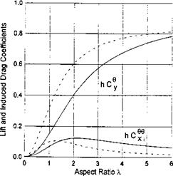 Fig. 3.11. The influence of the planform of the wing on the lift and induced drag coefficients for different magnitudes of the aspect ratio (dashed lines correspond to a semielliptic flat wing; solid lines to a rectangular flat wing).
where the coefficients an and bn are equal to
![]() 4(-l)r
4(-l)r
{1 +tanh^„i)„tanh[gn(l – bf)]}Agn’
The lift coefficient can be found as
n _ д M _ tanhgnbf tanh(g„bf/2) + tanh[gTI(l – bf)] tanhg„b/
![]()
 |
у f у h2 q*{l +tanh[q„(l – 6f)] tanhq„6f}
(3.82)
The coefficient of the longitudinal moment with respect to the hinge axis of the flap is
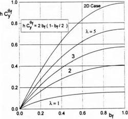
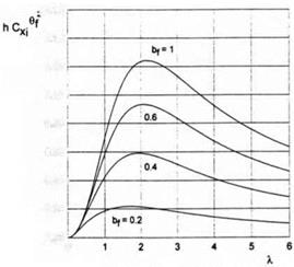 Fig. 3.12. The lift coefficient of a rectangular wing in the extreme ground effect versus the relative chord of the flap for different magnitudes of the aspect ratio.
![]()
![]() Fig. 3.13. The induced drag coefficient of a rectangular wing in the extreme ground effect versus the relative chord of the flap for different magnitudes of the aspect ratio.
Fig. 3.13. The induced drag coefficient of a rectangular wing in the extreme ground effect versus the relative chord of the flap for different magnitudes of the aspect ratio.
m. = S, mi = § f; _
hX Qn t cosh qnbf qn )
![]()
![]() Qn 2 J
Qn 2 J
The coefficient of the induced drag
Q = У’ (tanh(gnbf/2) + tanh[gn(l – 6f)]}2 tanh2 qnb{ X’ 9n(! + tanh[g„(l – bf) tanhqvA}2 ‘
Figures 3.12 and 3.13 illustrate the dependence of the parameters hCy1, and hCXi/6f upon the aspect ratio of the wing for different chords of the flap.
Consider another limiting case of a wing of small aspect ratio A <C 1. In this case, due to elongation of the wing in the direction of the flow, instead of a three-dimensional Laplace equation, a two-dimensional equation can be considered:
dV d2y
dy2 + dz2
For a wing with a slow increase in local span chordwise, it is sufficient to investigate a flow in a transverse plane passing through the trailing edge of the wing. Here it is convenient to render the problem nondimensional by a semispan //2 of the wing and speed U0 and introduce relative ground clearance, based on the span of the wing at the trailing edge h = h/l. For a flat wing, the corresponding velocity potential should satisfy the flow tangency condition on the wing and on the ground:
dp. . dp
Ty=-e• v=2h>’ <!=0′ »=°-
Following the general algorithm, one can demonstrate the main stages of the solution. For h <C A <C 1, the channel flow is described by the following relationships:
<pi = <Ph + %hm2 ln 2^ + + °(^i2)>
![]() d2p в ~d£ = 2h{
d2p в ~d£ = 2h{
In accordance with the general scheme, the potential of the upper flow pu is constructed by placing along the segment — 1 < x < 1 a distribution of sources with strength 6/h with the addition of admissible point sources at the points z = dil. These point sources model (in the upper flow) the leakage of air from beneath the wing around its edges. Then
<Pu = 2/ll^U! +0 (/if),
v"’=^in(i-22)-2bL>n{z~<)d<
= ^ІП^ “ 2^ ~ 2/^^ + ln^ + z) + (! – z) Ч1 – z) ~ 2]-
For a vanishingly thin and flat side edges, the structure of the edge potential remains the same as earlier:
Pe = 2haipae + 4/i12a2(£be + 4/г2а3г/ + 2ftia4,
where v — (z — l)/2h at the right tip and v = (—1 — z)/2h at the left tip of the wing.
Asymptotic matching of the velocity potentials y? i, and ipe leads to the following results
• Constants a, i
1 / в 7T
a3 = s(ai^slns;);
• Boundary conditions for the channel flow potential under the wing
¥>i(±l) = 2hi(a4 – ^)
Ws(±l) = ^ -0i(l + lnir) + A(2_ln2)
![]() For the problem of the leading order, в
For the problem of the leading order, в
![]() Ah
Ah
wherefrom it follows that in the extreme ground effect, the span – wise distribution of circulation for a wing of small aspect ratio is parabolic. It is easy to see that the corresponding downwash distribution is uniform. In accordance with Munk’s theorem, such a wing is optimal, i. e., has minimum induced drag for a given lift coefficient.
Including approximations of the order of 0(/ц), the following expression for the lift coefficient of a wing of small aspect ratio can be obtained:
To the leading order, the induced drag coefficient can be derived by using formula (2.109) in the form
![]() CXl
CXl
or in Prandtl’s representation,
|
X – l |
[___ і ^ |
||
|
h = o. os/* s |
|||
|
% = 0:07 |
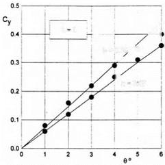
Fig. 3.5. Comparison of calculated results for a flat plate for different ground clearances with experimental data (Л — 1, solid lines: theory; circles: experiment).
Formulas (3.49) and (3.50) hold for a small-aspect-ratio wing of arbitrary planform.[13] Turning to a rectangular wing l = A, h = h = h/A, one can derive from (3.49), (3.50) that
|
ex |
f 6h , 7Г ‘ |
/ 6h |
7tA |
(3.51) |
|
|
: 6ЛІ1 |
(1 + ^>аГ. |
)=6Ґ |
(1 + ^ЛІП |
-)■ |
|
|
a2 |
A |
||||
|
cXl = |
II |
37Г /і’ |
Ae = A/z, |
(3.52) |
where h is the relative ground clearance based on the root chord, and Ae is the effective aspect ratio of the wing. Figure 3.5 presents a comparison of calculated results for A = 1, obtained by (3.51), with experimental results of Ermolenko et al. [133].
Within the assumption of a small aspect ratio, it is easy to consider the steady flow problem for a wing with curvilinear lateral curvature. Let the gap distribution be described as
/і*(ж, z) = 2hH(z) + to,
where h is the ground clearance based on the span, в is a pitch angle, and H(z) is a function of the order of 0(1) characterizing the form of the wing in the lateral direction, H(0) = 1. In this case, the linearization of (2.22) results in the following channel flow equation for a small-aspect-ratio wing with a curvilinear lateral axis:
This equation should be solved with boundary conditions
In the general case of a wing with a nonzero angle of heel ai(l) ф ni(—1)
ai(±l) = -^(±1)-
The potential of the upper flow ipu for a wing with a curvilinear lateral axis has the form
<pn ~ 2h(f>ni,
<Au = —oi(l) ln(l – z) + —ai(—1) ln(l + z)
7Г 7Г
|
C2dC tf(0’ |
|
C3dC H«Y |
 |
To the leading order, the expressions for the coefficients of the lift and lateral moment of wings of a small aspect ratio with a curvilinear lateral axis
Taking into account that, to the leading order, the lift coefficient of a flat plate of small aspect ratio is equal to Cyip = 9X/6h, we obtain the following formula, which allows estimating the relative influence of the lateral curvature of a wing in the ground effect
Consider some simple lateral forms of the lifting surface. Lateral configuration in the form of a “hat” is described by the function
H1(z) = l-(l-j^)z, г Є [-1,1].
In addition, we introduce parabolic and elliptic lateral configurations, represented, respectively, by the functions
-t+(* ■- £)^ w -£+ (‘ – £) ■
 |
Fig. 3.7. Relative lateral moment coefficient versus heel angle for small-aspect-ratio wings with different spanwise configurations (1: “hat;” 2 : parabolic; 3: elliptic).
Figure 3.6 illustrates the relative influence of the lateral curvature of the wing upon its lift coefficient for different magnitudes of the gap between the tips and the ground plane. Figure 3.7 shows the relative influence of the angle of heel upon the lateral moment coefficient mx for small-aspect-
ratio wings of different spanwise configurations. This parameter characterizes the static lateral stability of the wing, i. e., the capacity to restore its upright position after the action of heeling perturbations. Note that Fig. 3.7 compares the behavior of the ratio of the lateral moment coefficient mx for a given configuration to that of a flat plate mXfp versus heel angle /3.
The induced drag coefficient for a wing with a curvilinear lateral axis can be found by using (2.109) in the form
Consider a slightly curved infinitely thin foil, moving steadily near a solid flat ground plane with an angle of pitch в. In this case with asymptotic error of the order of 0(/i2), the flow under the foil does not differ from the one-dimensional, and the channel flow potential is governed by the following elementary equations:
 |
¥>i = <Ph +hn – iph + htpз + О(h2)
![]() й,= 2^1(0) = °,
й,= 2^1(0) = °,
й,=2^(0) = -^[В1-уі(0)1птг],
where ys(x) = h + sf(x) is a distribution of the gap between the foil and the ground and f(x) = 0(1) characterizes the position of the foil with respect to the line у = h. Parameters A2 and B have been described earlier.
We construct the upper flow potential by a distribution along the segment 0 < x < 1 of two-dimensional sources (sinks) whose strength is determined on the basis of the thin body theory as [—2yf8(x)]. Additionally, one should account for the admissibility of a point source solution at the leading edge, i. e., at x = 1,2/ = 0 + 0. Note that this latter solution does not violate the flow tangency condition on the upper surface of the foil.
Thus, the values of the upper flow potential at the points of a foil on its upper surface (0 < x < 1) are given by the expression
~hipUl]
V’ui = ln(l – x)~- j y’s(£) In (a; – f) df. (3.35)
І7Г 7Г J0
The strength of the point source in accordance with (2.70) is equal to
Q = 2^±(l). (3.36)
Asymptotic expansions of a potential (pu near the edges are obtained in the following form:
Near the trailing edge,
h _//лч . hB hB2
¥?u – – ув(0)і/пі/ ———— v——— ,
7Г 7Г 7Г
where и = —x:
Bx = Q-y’s(o)-
B2 = – f y’s(0 ln£d£. Jo
The solution of equations (3.32) with boundary conditions (3.33) and (3.34) can be written as follows:
<Ph= [ y’s(£)d£ = Vs(x) -&(1) = ya(x) -1;
|
Ув([12]). |
JO
W2 = (0) + <Pi2 (1) – 92 (0);
9h = xtP3(°) + Vut1) “ ¥»I3(°)’
Uniformly valid additive expressions for the velocity potential on the upper and lower surfaces of the foil are
|
+h{<Pb*(vi) – “Ув(°) hvі[1п(тгі/і) – 1]}; |
|
9ъе(*) – Ьу’вО)^2 – ^v)] |
![]()
= ¥>+(*) – 4™) + h{<Pbe(v) – ~y’s(0 hvb(nv) – 1]}
where P — (x — l)//i, Pi = —xjh. Functions,<pае?^ье’^ье are calculated by formulas (2.43) and (2.52), in which P has to be replaced by P.
Differentiating (3.39) and (3.40) with respect to x, one can find uniformly valid expressions for the pressures on the upper and lower surfaces of the foil
|
^be* |
It is convenient to take into account the following relationships:
We calculate the lift coefficient
Cy = l[v~~v*)ix=2l (^“^r)dx=2|v+(0)“^(<))l
= 2[<pu(0) – <pi(0)] = —2[<^i(0) – hipUl (0)] + О(h2).
Setting x = 0 in expressions (3.39) and (3.40) and representing the foil ordinates as ys = h + £f(x), where /(x) = 0(1), we obtain the following formula for the lift coefficient of a slightly curved foil in the ground effect:
C2 = -[/(!) + /'(0)];
^3 = “{/(1) ІП7Г + /'(0)(1 + In 7Г) + 1 [/,(0 ^ /,(0) + /'(£) In 1Л] d^}.
Here axe some examples:
• For a flat plate at an angle of pitch 0, the form function f(x) = x and
formula (3.41) is reduced to that obtained by Widnall and Barrows [40]:
0 ![]()
л Ah 7Г 2 h
Cy = T(l + — ІП-Г + — •
У h 7Г h 7Г /
Note that the same result can be obtained from the asymptotic analysis of the exact solution of the nonlinear flow problem for a flat plate in the ground effect derived by Tomotika et al. [27] for в —> 0, h —> 0 and 9/h —> 0. Figure
3.1
![Подпись: 2.0 Fig. 3.1. Distribution of the pressure coefficient on the upper and lower surfaces of a flat plate [40], h = 0.1. The dashed line corresponds to a one-term asymptotic solution. The difference between the three-term asymptotic solution and the results of the collocation method (solid lines) is indistinguishable.](/img/3131/image181_1.gif) |
illustrates the distribution of the pressure coefficient along the upper and lower surfaces of the flat plate in comparison with the results obtained by collocation. •
• Flat plate with a flap
Let the flap have a chord equal to bf and a deflection angle Of. In this case the form function is described by the equation f(x) = x, for 0 < x < bf, and f(x) = bf, for bf < x. Generally speaking, the foil can be oriented with respect to the ground at an angle of pitch 0, but in linear theory it is sufficient to study the case в = 0, Of Ф 0.
Note that in the vicinity of the hinge of the flap, the channel flow cannot be considered one-dimensional no matter how small the relative ground clearance h. Therefore, one has to analyze a local flow near the hinge. First of all, use the local coordinate system Xf = bf — x, yf = y. Introduce stretched coordinates yf = yfjh, Xf = Xf/h. After stretching, the local region near the hinge transforms into a strip (0 < yf < 1, |xf| < oo), on the boundary of which a normal derivative of the flow potential is known. Mapping the strip onto a half plane and using the Schwartz formula (see Fuks and Shabat [131]), one can write the expression for the flow perturbation velocity on the lower surface of the foil near the hinge as
= ~“^[ІП |1 “ eXp(-7TXf)| + 7TXf] + R,
where R is a constant. In the immediate vicinity of the hinge (xf -> 0),
![]() Of 1 _
Of 1 _
—– — In xf.
7Г h
Far from the hinge:
• To the left,
_ do2f _ _
Xf -> —oo, – д — ~ R + 0[exp(7TXf)], iff Rxf + Ді; (3.44)
• To the right,

![]()
Xf -> +oo,
Turning to the following result
Wl(bf + 0) = Wl(bf-0) (3.46)
It follows from (З.46) that for h -» 0, the magnitudes of both the potential <px and the perturbation velocity d<pxjdx in the channel flow are equal when approaching the hinge from the left and right-hand sides.
where </?ae is given by (2.43), v = (x – l)/h, Di — -x/h. Representative distributions of the pressure coefficient on a foil with a flap are plotted in Fig. 3.2.
Due to the fact that the perturbations under the foil induced by the hinge decay exponentially, the lift coefficient can be derived from the general formula (3.41) as
с„ = с, Ч = |{й,(і-^) + ^і„і(і + ад
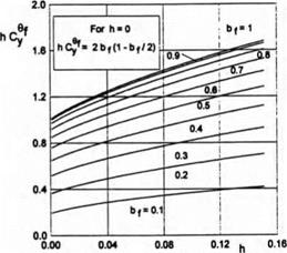
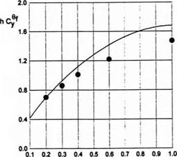
Parameter hCp versus ground clearance and the length of the flap is plotted in Fig. 3.3. In Fig. 3.4 a comparison is presented of the results of the present theory with calculated data of Shadrin [132] based on the method of the r-parameter.
|
Fig. 3.3. Parameter hC9y versus the relative ground clearance and the length of the flap, Л = oo. |
|
Fig. 3.4. Comparison of the calculated results for a flat plate of infinite aspect ratio, h=0.15. Solid line: MAE; circles: from [132]. |
|
d[9]p d2p d2p dx2 dy2 dz2 |
A linear formulation for the perturbed velocity potential of absolute motion can be easily derived from the nonlinear formulation in the form
Signs “plus” and “minus” correspond to the upper and lower surfaces. • Flow tangency condition on the ground:
• Dynamic condition of pressure continuity across the wake: P~ =P+, У = h, (x, z) Є W
![]()
or
so that p = p{x, у, z, t) and rewrite (3.6) as
Equation (3.8) can be demonstrated to be identical to the following set of equations:
ip+(x, h,z, t) – ip (x, h,z, t)=(p+(xte, h,z,0)~<p (xte, h,z, 0),
(x, z)eW, x-xte{z)+t = 0, (3.9)
where xte = Xte(^) is the equation of the trailing edge in the adopted coordinate system.[10] In terms of “physical” time £,
|
f U(t)dt = 0. Jt[11] |
ip+(x, h,z, t) – <p (x, h,z, t) = ip+(xte, h,z, t*) -<p (xte, h,z, t*),
In fact, the alternative forms (3.9),(3.10) of the dynamic boundary condition (3.5) in the wake correspond to the Kelvin (Thomson) theorem and express the jump of the velocity potential across the vortex sheet at an arbitrary point of the latter, if this jump is known at any time at the trailing edge of the wing. The Kutta-Zhukovsky condition at the trailing edge can be viewed as incorporated into the above dynamic condition in the wake.
• The continuity of the vertical component of the flow velocity across the wake:
Linearizing the kinematic condition (2.5), we derive
• Decay of perturbations at infinity:
x2 + y2 + z2 oo. (3.12)
In channel flow, the same asymptotic expansion (2.11), as earlier, can be utilized, although in the linear case
= оф«1. (3.13)
Using the linearized version of the procedures, demonstrated in 2.2, one can show that the channel flow equation is identical to the Poisson equation
where h* = h*/h = y — yg = 1 + О (є/ft), whereas
![]()
![]() (3.15)
(3.15)
For channel flow under the wake a similar equation holds, but in this case it has to be solved with respect to the induced downwash
The components of the induced downwash in the wake can be determined by a linearized version of (2.24), namely,
|
U(t*)dt* U(t*)dt |
Using the dynamic condition in the wake in the Kelvin (Thomson) form (3.10), one can calculate aw as
where t* is related to x and t by equation (3.10).
For a steady flow with asymptotic error О (ft), the downwash in the wake is not dependent on x. With this in mind, determination of aw ~ aWl becomes still simpler:
_ _ <92
cyw 00 cyWl = ^^2 <Ph z)’ (3.19)
The flow above the lifting system and its wake (upper flow) is identical to what was considered previously. The upper flow potential (fu is of the order of 0(e) and, to the lowest order, is described by an expansion
in which (pUl is represented by (2.31) and has the “edge” asymptotics given by (2.32) and (2.33).
Local flows are linearized consistent with the overall linearization scheme. Stretching of local coordinates is performed by the ground clearance h rather than the local instantaneous distance /і* of the edge from the ground as in the nonlinear case. Otherwise, all previous results of section 2 hold for the linear case.
 |
|
The boundary condition for the channel flow equation (3.14) at the leading (side) edge li for an infinitely thin edge can be derived from (2.73) setting hi = 1. Then
The boundary condition for the channel flow equation (3.14) at the trailing edge /2 for a sharp straight edge can be derived from (2.98) setting h* = 1. Then
Pi* = 2
The coefficients of the lift and moments are given by formulas (2.104)—(2.106), but the pressures on the upper and lower surfaces of the wing are both calculated by using linear differential operators
Within the linearized formulation, the extreme ground effect case has a still simpler mathematical description than in the nonlinear theory. Corresponding relationships have the form
Transition points, separating the leading (side) and trailing edges, are coincident with the wing tips.