Category AERODYNAMICS

THE STREAM FUNCTION

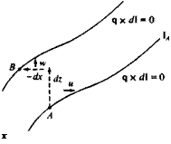
Consider two arbitrary streamlines in a two-dimensional steady flow, as shown in Fig. 2.17. The velocity q along these lines 1 is tangent to them

Подпись: (1.5)qx dl = иdz – wdx = 0

FIGURE 2.17

Подпись: x Flow between two two-dimensional streamlines.

and, therefore, the flux (volumetric flow rate) between two such lines is constant. This flow rate between these two curves is

image69•nd/= udz + w(—dx) (2.73)

‘a

Подпись: <9W dz THE STREAM FUNCTION Подпись: (2.74)

where A and В are two arbitrary points on these lines. If a scalar function W(*, z) for this flux is to be introduced, such that its variation along a streamline will be zero (according to Eq. (1.5)), then based on these two equations (Eqs. (1.5) and (2.73)), its relation to the velocity is

Substituting this into Eq. (1.5) for the streamline results in

Подпись: -w dx + udz = 0Подпись: (2.75)aw aw

dW = — dx+ — dz = dx dz

Therefore, dW along a streamline is zero, and between two different streamlines dW represents the volume flux (Eq. (2.73)). Integration of this equation results in

Подпись: (2.76) (2.77) W = const. on streamlines Substituting Eqs. (2.74) into the continuity equation yields

Эи dw a2w a2w л

—- 1— —————— — 0

dx dz dx dz dx dz

and therefore the continuity equation is automatically satisfied. Note that the stream function is valid for viscous flow, too, and if the irrotational flow requirement is added then £y = 0. Recall that the у component of the vorticity

is

Подпись: Су^_^=V2ip

dz dx
and therefore for two-dimensional incompressible irrotational flow V satisfies Laplace’s equation

V2V = 0 (2.78)

It is possible to express the two-dimensional velocity in the x-z plane as

34» ЗУ

— i – — k=jXV4»

dz dx

Thus

q=jxVW (2.79)

Using this method, the velocity in cylindrical coordinates (for the r-d) plane is obtained:
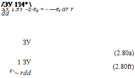
Подпись:q=j *

and the velocity components are

THE STREAM FUNCTION THE STREAM FUNCTION

The relation between the stream function and the velocity potential can be found by equating the expressions for the velocity components (Eq. (2.20) and Eq. (2.74)), and in cartesian coordinates:

These are the Cauchy-Riemann equations with which the complex flow potential will be defined in Chapter 6.

Laplace’s equation in polar coordinates, expressed in terms of the stream function, is

Подпись: v2y =Подпись: (2.83)32У 1ЭУ 1 32У dr2 + r dr + r2 dd2

To demonstrate the relation between the velocity potential and the stream function, recall that along a streamline

Подпись: (2.84)dy = udz — wdx = Q

and similarly, along a constant potential line

d<& = udx + w dz = Q (2.85)

Since the slopes of the streamlines and the potential lines are negative reciprocals, these lines are perpendicular to one another at any point in the flow.

THE VELOCITY INDUCED BY A STRAIGHT VORTEX SEGMENT

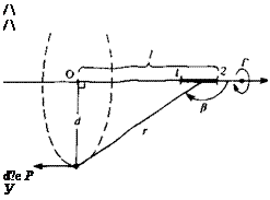
In this section, the velocity induced by a straight vortex line segment is derived, based on the Biot-Savart law. It is clear that a vortex line cannot start or end in a fluid, and the following discussion is aimed at developing the contribution of a segment that is a section of a continuous vortex line. The vortex segment is placed at an arbitrary orientation in the (x, y, z) frame with constant circulation Г, as shown in Fig. 2.14. The velocity induced by this

Подпись: /  /  d?e P У
Подпись: z

FIGURE 2.14

Velocity induced by a straight vortex segment.

Подпись: vortex segment will have tangential components only, as indicated in the figure. Also, the difference r0 -14 between the vortex segment and the point P is r. According to the Biot-Savart law (Eq. 2.68a) the velocity induced by a segment dl on this line, at a point P, is 4 Г dl X r A, = 4* r' (2.68 b) This may be rewritten in scalar form л r sin P J, A<7e = 2 dl Ал r (2.68c)

From the figure it is clear that

d = r cos /3

d

l = d tan в and dl = —5— dp

cos p

Substituting these into Дqe

Подпись:—%To dP = T~Jsin P dP

cos P And

This equation can be integrated over a section (1—»2) of the straight vortex segment of Fig. 2.15

(<?e)1’2 = 4ndjp sin PdP = ^ (cos /^i – cos P2) (2.69)

The results of this equation are shown schematically in Fig. 2.15. Thus, the velocity induced by a straight vortex segment is a function of its strength Г, the distance d, and the two view angles /3,, p2.

For the two-dimensional case (infinite vortex length) рг=0, p2~ л and

image63(2.70)

For the semi-infinite vortex line that starts at point О in Fig. 2.14, /31 = л/2 and p2 = л and the induced velocity is

image64(2.71)

which is exactly half of the previous value.

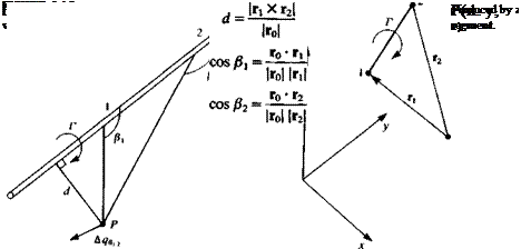
Equation (2.68b) can be modified to a form that is more convenient for numerical computations by using the definitions of Fig. 2.16. For the general three-dimensional case the two edges of the vortex segment will be located by Г! and r2 and the vector connecting the edges is

ro = r2 – rl

FIGURE 2.16

image65,image66

as shown in Fig. 2.16. The distance d, and the cosines of the angles /3 are then

The direction of the velocity qt 2 is normal to the plane created by the point P and the vortex edges 1, 2 and is given by

fi Xr2

ІГі X r2|

and by substituting these quantities, and by multiplying with this directional vector the induced velocity is

image67(2.72)

A more detailed procedure for using this formula when the (x, y, z) values of the points 1, 2, and P are known is provided in Section 10.4.5.

THE BIOT-SAVART LAW

At this point we have an incompressible fluid for which the continuity equation is

V • q = 0 (1.23)

and where vorticity £ can exist and the problem is to determine the velocity field as a result of a known vorticity distribution. We may express the velocity field as the curl of a vector field B, such that

q = V X В (2.64)

Since the curl of a gradient vector is zero, В is indeterminate to within the gradient of a scalar function of position and time, and В can be selected such that

Подпись: (2.65)V-B = 0

The vorticity then becomes

% = V X q = V X (V X B) = V(V • B) – V2B

By applying Eq. (2.65) this reduces to Poisson’s equation for the vector potential B:

$=-V2B (2.66)

The solution of this equation, using Green’s theorem (see Karamcheti,15 p. 533) is

4л Jv |r0 —fi|

Here В is evaluated at point P (which is a distance r0 from the origin, shown in Fig. 2.12) and is a result of integrating the vorticity £ (at point r,) within the

image57FIGURE 2.12

Velocity at point P due to a vortex distribution.

image58,image59,image60

volume V. The velocity field is then the curl of В

image61

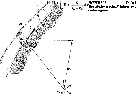
Before proceeding with this integration, let us consider an infinitesimal piece of the vorticity filament £, as shown in Fig. 2.13. The cross section area dS is selected such that it is normal to ^ and the direction d on the filament is

Also the circulation Г is

Г = £dS

and

dV = dS dl

so that

Подпись: ko-rjiV X -—-—- dV = V X Г ——-

and carrying out the curl operation while keeping r, and d fixed we get

rrvr dl _rdl*(rO~ri)

VXr|ro-r1|-r |r0-r,|3

Substitution of this result back into Eq. (2.67) results in the Biot-Savart law, which states

Подпись: (2.68)Подпись:Г Г dіх(г0-гі) 4л J |r0-rt|3

or in differential form

_ Г dl X (r0 – rt) 4л |г0-Гі|3

A similar manipulation of Eq. (2.67) leads to the following result for the velocity due to a volume distribution of vorticity:

-Lf txfrb-r,)^

4л Jy |r0-r,|3


(2.67a)


q


TWO-DIMENSIONAL VORTEX

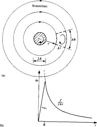
To illustrate a flowfield frequently called a two-dimensional vortex, consider a two-dimensional rigid cylinder of radius R rotating in a viscous fluid at a constant angular velocity of a>y, as shown in Fig. 2.11a. This motion results in a flow with circular streamlines and therefore the radial velocity component is zero. Consequently the continuity equation (Eq. (1.35)) in the г-в plane becomes

image53(2.54)

Integrating this equation results in

Подпись: (2.55)Чв = Чв{г)

The Navier-Stokes equation in the r direction (Eq. (1.36)), after neglecting the body force terms, becomes

image54(2.56)

Since qe is a function of r only, and owing to the radial symmetry of the problem the pressure must be either a function of r or a constant. Therefore, its derivative will not appear in the momentum equation in the в direction

image55

FIGURE 2.11

Two-dimensional flowfield around a cylindrical core rotating as a rigid body.

(Eq. 1.37),

SK

1

®l V <§!«& – її +

a.

II

о

(2.57)

and since qe is a function of r only,

0 = d/дЛ dr2 drr)

(2.58)

Integrating with respect to r yields

dqe,4e_ n

j ‘ — Cl

dr r

where Cj is the constant of integration. Rearranging this yields

and after an additional integration

cx C2

(2.59)

q,~T’*T

The boundary conditions are

qe – —Ro)y at r = R

(2.60a)

qe~0 at r = oo

(2.606)

image56

The second boundary condition is satisfied only if C, = 0, and by using the first boundary condition, the velocity becomes

From the vortex filament results (Eq. (2.53)), the circulation has the same sign as the vorticity, and is therefore positive in the clockwise direction. The circulation around the circle of radius r, concentric with the cylinder, is found by using Eq. (2.3)

Г = j qerdd = 2o)ynR2 (2.62)

hn

TWO-DIMENSIONAL VORTEX Подпись: (2.63)

and is constant. The tangential velocity can be rewritten as

This velocity distribution is shown in Fig. 2.116 and is called vortex flow. If r-*0 then the velocity becomes very large near the core, as shown by the dashed lines.

It has been demonstrated that Г is the circulation generated by the rotating cylinder. However, to estimate the vorticity in the fluid, the integration line shown by the dashed lines in Fig. 2.11a is suggested. Integrating the velocity in a clockwise direction, and recalling that qr = 0, results in

<£ q • d = 0 • Ar + – —^ – (r + A г) Д0-0•A r – ■— г Д0 = 0 7M 2 n(r + Ar) 2 лг

This indicates that this vortex flow is irrotational everywhere, except at the core where all the vorticity is generated. When the core size approaches zero (Л—»0) then this flow is called an irrotational vortex (excluding the core point, where the velocity approaches infinity).

The three-dimensional velocity field induced by such an element is derived in the next section.

VORTEX QUANTITIES

In conjunction with the velocity vector, we can define various quantities such as streamlines, stream tubes, and stream surfaces. Corresponding quantities can be defined for the vorticity vector that will prove to be useful later on in the modeling of lifting flows.

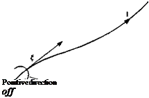
The field lines (e. g., in Fig. 2.2) that are parallel to the vorticity vector are called vortex lines and these lines are described by

t X d = 0 (2.46)

where d is a segment along the vortex line (as shown in Fig. 2.9). In cartesian coordinates, this equation yields the differential equations for the vortex lines:

Подпись: (2.47)dx _dy _dz

Z=Ty~Z

The vortex lines passing through an open curve in space form a vortex surface and the vortex lines passing through a closed curve in space form a vortex tube. A vortex filament is defined as a vortex tube of infinitesimal cross-sectional area.

The divergence of the vorticity is zero since the divergence of the curl of

Подпись: Positive direction off FIGURE 2.9

Vortex line.

any vector is identically zero:

V-£ = V- VXq = 0 (2.48)

Consider, at any instant, a region of space R enclosed by a surface S. An application of the divergence theorem yields

[ l-ndS= f V-%dV = 0 (2.49)

Js Jr

At some instant in time draw a vortex tube in the flow as shown in Fig. 2.10. Apply Eq. (2.49) to the region enclosed by the wall of the tube Sw and the surfaces Si and S2 that cap the tube. Since on Sw the vorticity is parallel to the surface, the contribution of Sw vanishes and we are left with

f £-ndS= f £-ndS+ f £-ndS = 0 (2.50)

Js Js, Js,

Note that n is the outward normal and its direction is shown in the figure. If we denote n„ as being positive in the direction of the vorticity, then Eq. (2.50) becomes

Подпись: dS = const.image50(2.51)

At each instant of time, the quantity in Eq. (2.51) is the same for any cross-sectional surface of the tube. Let C be any closed curve that surrounds the tube and lies on its wall. The circulation around C is given from Eq. (2.4) as

Подпись: Гс =Подпись:image51

Подпись: FIGURE 2.10 Vortex tube.
image52

(2.52)

and is seen to be constant along the tube. The results in Eqs. (2.51) and (2.52) express the spatial conservation of vorticity and are purely kinematical.

If Eq. (2.52) is applied to a vortex filament and it,, is chosen parallel to the vorticity vector, then

Гc = £dS = const. (2.53)

and the vorticity at any section of a vortex filament is seen to be inversely proportional to its cross-sectional area. A consequence of this result is that a
vortex filament cannot end in the fluid since zero area would lead to an infinite value for the vorticity. This limiting case, however, is useful for the purposes of modeling and so it is convenient to define a vortex filament with a fixed circulation, zero cross-sectional area, and infinite vorticity as a vortex filament with concentrated vorticity.

Based on results similar to those of Section 2.3 and this section, the German scientist Hermann von Helmholtz (1821-1894) developed his vortex theorems for inviscid flows, which can be summarized as:

1. The strength of a vortex filament is constant along its length.

2. A vortex filament cannot start or end in a fluid (it must form a closed path or extend to infinity).

3. The fluid that forms a vortex tube continues to form a vortex tube and the strength of the vortex tube remains constant as the tube moves about (hence vortex elements, such as vortex lines, vortex tubes, vortex surfaces, etc., will remain vortex elements with time).

The first theorem is based on Eq. (2.53), while the second theorem follows from this. The third theorem is actually a combination of Helmholtz’s third and fourth theorems and is a consequence of the inviscid flow assumption (Eq. (2.9)).

UNIQUENESS OF THE SOLUTION

The physical problem of finding the velocity field for the flow created, say, by the motion of an airfoil or wing has been reduced to the mathematical problem of solving Laplace’s equation for the velocity potential with suitable boundary conditions for the velocity on the body and at infinity. In a space-fixed reference frame, this mathematical problem is

Подпись:У2Ф = 0

Подпись:ЭФ к я

= n • qs on bod

УФ —» 0 at r —> °°

Since the body boundary condition is on the normal derivative of the potential and since the flow is in the region exterior to the body, the mathematical problem of Eqs. (2.37a, b, c) is called the Neumann exterior problem. In what follows we will answer the question “is there a unique solution to the Neumann exterior problem?” We will discover that the answer is different for a simply and multiply connected region.

Let us consider a simply connected region first. This will apply to the region outside of a three-dimensional body but care must be taken in extending the results to wings since the flowfield is not irrotational everywhere (wakes). Assume that there are two solutions Ф, and Ф2 to the mathematical problem posed in Eqs. (2.37a, b, c). Then the difference

Фі – Ф2 = Ф0

satisfies Laplace’s equation, the homogeneous version of Eq. (2.37b), and Eq. (2.37c).

One form of Green’s (George Green, German mathematician, early 1800’s) theorem (Ref. 1.5, p. 135) is obtained by applying the divergence theorem to the function Ф УФ where Ф is a solution of Laplace’s equation, R is the fluid region and S is its boundary. The result is

f Г ЭФ

J V<t>-V<PdV = J Ф — dS (2.38)

Now apply Eq. (2.38) to Ф0 for the region R between the body В and an arbitrary surface 2 surrounding В to get

f VФD • УФД dV = f Ф„^<« + f Ф0^5 (2.39)

Jr Jb Jz

If we let 2 go to infinity the integral over 2 vanishes and since Эф0/дп = 0 on В we are left with

f VФD^VФDdV = 0 (2.40)

Jr

Since the integrand is always greater than or equal to zero, it must be zero and consequently the difference Фі — Ф2 can at most be a constant. Therefore, the solution to the Neumann exterior problem in a simply connected r^»Vn ia unique to within a constant

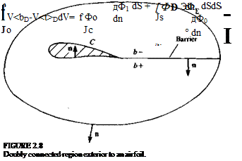
Consider now the doubly connected region exterior to the airfoil C in Fig. 2.8. Again let Ф! and Ф2 be solutions and take

Ф, Ф = Ф0

Green’s theorem is now applied to the function Фв in the region о between the airfoil C and the curve 2 surrounding it. Note that the integrals are still volume and surface integrals and that the integrands do not vary normal to the plane of motion.

UNIQUENESS OF THE SOLUTION Подпись: (2.41)

Insert a barrier b joining C and 2 and denote the two sides of the barrier as b— and b+ as shown in the figure. Note that n is the outward normal to b— and — n is the outward normal to b+. Equation (2.38) then becomes

The integral around C is zero from the boundary condition and if we let 2 go to infinity the integral around 2 is zero also. Let Фр be Ф0 on b – and Фр be Ф0 on b+. Then Eq. (2.41) is

f УФР • УФ0 dV = | ФЪ^-dS – JT ФІ^dS (2.42)

The normal derivative of Фр is continuous across the barrier and Eq. (2.42) can be written in terms of an integral over the barrier:

f 7Ф* • dV = f (ФБ – Ф£) ^ dS (2.43)

Jo ^barrier

If we reintroduce the quantities Ф, and Ф2 and rearrange the integrand we get f УФ о • УФо dV=f (Ф Г – ФЇ + Ф2+ – Ф2~) ^ dS (2.44)

Ja ^barrier

Note that the circulations associated with flows 1 and 2 are given by

Г, = Ф^-ФГ

г2 = ф2+-ф2-
and are constant, and finally

f V<PD • V<&D dV = (T2 – Г0 f ^ ds (2.45)

*o -^barrier

Since in general we cannot require that the integral along the barrier be zero, the solution to the Neumann exterior problem is only uniquely determined to within a constant when Г, = Г2 (when the circulation is specified as part of the problem statement). This result can be generalized for multiply connected regions in a similar manner. The value of the circulation cannot be specified on purely mathematical grounds but will be determined later on the basis of physical considerations.

SIMPLY AND MULTIPLY CONNECTED REGIONS

The region exterior to a two-dimensional airfoil and that exterior to a three-dimensional wing or body are fundamentally different in a mathematical sense and lead to velocity potentials with different properties. To point out the difference in these regions, we need to introduce a few basic definitions.

A reducible curve in a region can be contracted to a point without leaving the region. For example, in the region exterior to an airfoil, any curve surrounding the airfoil is not reducible and any curve not surrounding it is reducible. A simply connected region is one where all closed curves are reducible. (The region exterior to a finite three-dimensional body is simply connected. Any curve surrounding the body can be translated away from the body and then contracted.) A barrier is a curve that is inserted into a region but is not a part of the resulting modified region. The insertion of barriers into a region can change it from being multiply connected to being simply connected. The degree of connectivity of a region is n +1 where n is the minimum number of barriers needed to make the remaining region simply connected. For example, consider the region in Fig. 2.6 exterior to an airfoil. Draw a barrier from the trailing edge to downstream infinity. The original region minus the barrier is now simply connected (note that curves in the region can no longer surround the airfoil). Therefore n = 1 and the original region is doubly connected.

Consider irrotational motion in a simply connected region. The circula­tion around any curve is given by

r = <J>q-<fl = <J>V<&-dl = (2.36)

Подпись: FIGURE 2.6 Flow exterior to an airfoil in a doubly connected region. Barrier

___/____________________

image46

With the use of Eqs. (2.4) and with £ = 0 the circulation is seen to be zero. Also, since the integral of гіФ around any curve is zero (Eq. (2.36)), the velocity potential is single-valued.

image47

Now consider irrotational motion in the doubly connected region exterior to an airfoil as shown in Fig. 2.7. For any curve not surrounding the airfoil, the above results for the simply connected region apply and the circulation is zero. Now insert a barrier as shown in the figure. Consider the curve that consists of Ci and C2, which surround the airfoil, and the two sides of the barrier. Since the region excluding the barrier is simply connected, the circulation around this curve is zero. This leads to the following equation:

Note that the first term is the circulation around C, and the second is minus the circulation around C2. Also, the contributions from the barrier cancel for steady flow (since the barrier cannot be along a vortex sheet). The circulation around curves Cx and C2 (and any other curves surrounding the airfoil once) are the same and may be nonzero. From Eq. (2.36) the velocity potential is not single-valued if there is a nonzero circulation.

BERNOULLI’S EQUATION FOR THE PRESSURE

The incompressible Euler equation (Eq. (1.31)) can be rewritten with the use of Eq. (2.5) as

^-4X^ + V^=/-V^ (2.29)

For irrotational flow £ = 0 and the time derivative of the velocity can be written as

^ = |v«I> = v(^) (2.30)

at at at)

Let us also assume that the body force is conservative with a potential E,

f = – VE (2.31)

If gravity is the body force acting and the z axis points upward, then E = ~gz. The Euler equation for incompressible irrotational flow with a conservative body force (by substituting Eqs. (2.30) and (2.31) into Eq. (2.29)) then becomes

V(£ + ^+2+f)-° <2’32>

Equation (2.32) is true if the quantity in parentheses is a function of time only:

n q2 ЗФ

Е + Е + + — =т (2.33)

p 2 at

BERNOULLI’S EQUATION FOR THE PRESSURE Подпись: (2.34)

This is the Bernoulli (Dutch/Swiss mathematician, Daniel Bernoulli (1700-1782)) equation for inviscid incompressible irrotational flow. A more useful form of the Bernoulli equation is obtained by comparing the quantities on the left-hand side of Eq. (2.33) at two points in the fluid, an aribtrary point and a reference point at infinity, say. The equation becomes

If the reference condition is chosen such that E„ = 0, Фоо = const., and q,» = 0 then the pressure p at any point in the fluid can be calculated from

Подпись: (2.35)€^z£ = — + e + —

p dt 2

If the flow is steady, incompressible but rotational the Bernoulli equation (Eq.

(2.34) ) is still valid with the time-derivative term set equal to zero if the constant on the right-hand side is now allowed to vary from streamline to streamline. (This is because the product q x £ is normal to the streamline d and their dot product vanishes along the streamline. Consequently, Eq. (2.34) can be used in a rotational fluid between two points lying on the same streamline.)

BOUNDARY AND INFINITY CONDITIONS

Laplace’s equation for the velocity potential is the governing partial differential equation for the velocity for an inviscid, incompressible, and irrotational flow. It is an elliptic differential equation that results in a boundary-value problem. For aerodynamic problems the boundary conditions need to be specified on all solid surfaces and at infinity. One form of the boundary condition on a solid-fluid interface is given in Eq. (2.22). Another statement of this boundary condition, which will prove useful in applications, is obtained in the following way.

Let the solid surface be given by

F(x, y, z, t) = 0 (2.23)

in cartesian coordinates. Particles on the surface move with velocity qB such that F remains zero. Therefore the derivative of F following the surface particles must be zero:

/ D dF

Ы/-37+«*-vf = ° <2-24>

Equation (2.22) can be rewritten as

q • VF = qs • VF (2.25)

BOUNDARY AND INFINITY CONDITIONS Подпись: (2.26)

since the normal to the surface n is proportional to the gradient of F.

If Eq. (2.25) is now substituted into Eq. (2.24) the boundary condition

dF „ DF

Подпись:Подпись: becomes
—- l-q – VF = —— = 0

at 4 Dt

At infinity, the disturbance q due to the body moving through a fluid that was initially at rest decays to zero. In a space-fixed frame of reference the velocity of such fluid (at rest) is therefore zero at infinity (far from the solid boundaries of the body):

lim q = 0 (2.28)

IRROTATIONAL FLOW AND THE VELOCITY POTENTIAL

It has been shown that the vorticity in the high Reynolds number flowfields that are being studied is confined to the boundary layer and wake regions where the influence of viscosity is not negligible and so it is appropriate to assume an irrotational as well as inviscid flow outside these confined regions. (The results of Sections 2.2 and 2.3 will be used when it is necessary to model regions of vorticity in the flowfield.)

Consider the following line integral in a simply connected region, along the line C:

Подпись: (2.17)/ q • dl = і udx + vdy + wdz

Jc ‘c

If the flow is irrotational in this region then udx + vdy + wdz is an exact differential (see Kreyszig,2 1 p. 741) of a potential Ф that is independent of the integration path C and is a function of the location of the point P(x, y, z):

Ф(x, y, z)=f udx + vdy + wdz (2.18)

JPo

where P0 is an arbitrary reference point. Ф is called the velocity potential and the velocity at each point can be obtained as its gradient

q = УФ

(2.19)

and in cartesian coordinates

ЗФ

ЭФ

ЭФ

(2.20)

и = ~

v = —-

w = ——

dx

dy

dz

The substitution of Eq. (2.19) into the continuity equation (Eq. (1.23)) leads to the following differential equation for the velocity potential

V • q = V • УФ = У2Ф — 0 (2.21)

which is Laplace’s equation (named after the French mathematician Pierre S. De Laplace (1749-1827)). It is a statement of the incompressible continuity equation for an irrotational fluid. Note that Laplace’s equation is a linear
differential equation. Since the fluid’s viscosity has been neglected, the no-slip boundary condition on a solid-fluid boundary cannot be enforced and only Eq. (1.28a) is required. In a more general form, the boundary condition states that the normal component of the relative velocity between the fluid and the solid surface (which may have a velocity qB) is zero on the boundary:

■•(q-4n) = 0 (2.22)

This boundary condition is physically reasonable and is consistent with the proper mathematical formulation of the problem as will be shown later in the chapter.

For an irrotational inviscid incompressible flow it now appears that the velocity field can be obtained from a solution of Laplace’s equation for the velocity potential. Note that we have not yet used the Euler equation, which connects the velocity to the pressure. Once the velocity field is obtained it is necessary to also obtain the pressure distribution on the body surface to allow for a calculation of the aerodynamic forces and moments.