For an example, increase the linear dimensions of a solid cube from 1 to 2 units. From the following example, it can be seen that the increase in weight is faster than the increase in area (the subscript 1 represents the small cube and the subscript 2 represents the larger cube):
area2 = area1 x (length2/length^2, a 4-fold increases from 6 to 24 square units volume2 = volume1 x (length2/length1)3, an 8-fold increase from 1 to 8 cube units
Applying this concept to a wing, increasing its span (i. e., linear dimension, b – maintaining geometric similarity) would increase its volume faster than the increase in surface area, although not at the same rate as for a cube. Volume increase is associated with weight increase, which in turn would require stiffening of the structure, thereby further increasing the weight in a cyclical manner. This is known as the square-cube law in aircraft design terminology. This logic was presented a halfcentury ago by those who could not envisage very large aircraft.
weight, W a span3 wing planform area, Sw a span2 (3.43)
Then,
wing-loading, W/Sw a b
This indicates that for the given material used, because of excessive weight growth, there should be a size limit beyond which aircraft design may not be feasible. If the fuselage is considered, then it would be even worse with the additional weight.
Yet, aircraft size keeps growing – the size of the Airbus A380 would have been inconceivable to earlier designers. In fact, a bigger aircraft provides better structural efficiency, as shown in Figure 4.6, for operating empty weight fraction (OEWF) reduction with maximum takeoff weight (MTOW) gain. Researchers have found that advancing technology with newer materials – with considerably better strength – to-weight ratio, weight reduction by the miniaturization of systems, better high-lift devices to accommodate higher wing-loadings, better fuel economy, and so forth – has defied the square-cube law. Strictly speaking, there is no apparent limit for further growth (up to a point) using the current technology.
The author believes that the square-cube law needs better analysis to define it as a law. Currently, it indicates a trend and is more applicable to weight growth with an increase in aspect ratio. What happens if the aspect ratio does not change? The following section provides an excellent example of how a low aspect ratio can compete with a high aspect-ratio design.
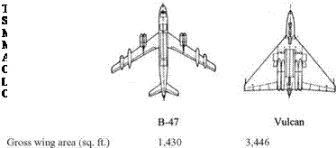
Figure 3.41. Torenbeek’s comparison between a B-47 and a Vulcan
3.20.2 Aircraft Wetted Area (AW) versus Wing Planform Area (Sw)
The previous section raised an interesting point on aircraft size, especially related to wing geometry. This section discusses another consideration on how the aircraft wing planform area and the entire aircraft wetted surface areas can be related. Again, the wing planform area, SW, serves as the reference area and does not account for other wing parameters (e. g., dihedral and twist).
The conflicting interests between aerodynamicists and stress engineers on the wing aspect ratio presents a challenge for aircraft designers engaged in conceptual design studies (this is an example of the need for concurrent engineering). Both seek to give the aircraft the highest possible lift-to-drag (L/D) ratio as a measure of efficient design. Using Equations 3.23 and 3.31, the following can be shown (i. e., incompressible flow):
drag, D = qSwCD = qSw(CDP + Cdi )
or
CD = (Cdp + CDi) (3.44)
Clearly, CDP a wetted area, AW and CDi is a (1/AR) = SW/b2 (from Equation 3.43).
Define the wetted-area aspect ratio as follows:
ARwet = b2 / Aw = AR/( Aw / Sw) (3.45)
This is an informative parameter to show how close the configuration is to the wing – body configuration. Section 4.5 provides statistical data for various designs.
Torenbeek [5] made a fine comparison to reveal the relationship between the aircraft wetted area, AW, and the wing planform area, Sw. Later, Roskam [6] presented his findings to reinforce Torenbeek’s point, whose result is shown in Figure 3.41.
|
Table 3.1. Wing span, aspect ratio, and reference area analyses
|
Type
|
AR
|
b – ft
|
Sw – ft2
|
Aw / Sw
|
b2/Aw
|
(L/ D)max
|
|
Small aircraft
|
|
|
|
|
|
|
|
Fixed wheel: Piper Cherokee
|
|
|
|
3.5 to 4.5
|
1.2 to 1.8
|
10 to 15
|
|
6.2
|
32.5
|
175
|
3.72
|
1.62
|
13.5
|
|
Retractable wheel: Learjet 45
|
|
|
|
4 to 5.5
|
1.4 to 2
|
12 to 16
|
|
7.5
|
49.2
|
323
|
5.05
|
1.48
|
15.8
|
|
Transport aircraft
|
|
|
|
|
|
|
|
Large/medium jets: A320
|
|
|
|
6 to 7
|
1.2 to 1.6
|
16 to 18
|
|
9.37
|
111.2
|
1,320
|
6.2
|
1.52
|
16.5
|
|
Regional jets: F28
|
|
|
|
5.5 to 7
|
1.1 to 1.3
|
15 to 17
|
|
7.3
|
77.4
|
822
|
5.7
|
1.29
|
15.5
|
|
Turboprop: SD330
|
|
|
|
5 to 7
|
1.1 to 1.8
|
14 to 17
|
|
12.3
|
75
|
453
|
6.73
|
1.8
|
15
|
|
Three-surface (with canard): Piaggio
|
|
|
|
4.5 to 6
|
0.5 to 1.0
|
10 to 12
|
|
Avanti
|
|
|
|
|
|
|
|
12.3
|
46
|
172.2
|
|
|
high
|
|
Military aircraft
|
|
|
|
|
|
|
|
Single-surface (delta wing): Vulcan
|
|
|
|
2.5 to 3
|
0.5 to 0.8
|
8 to 10
|
|
2.84
|
99
|
3,448
|
2.8
|
1.1
|
17
|
|
Two-surface (with H-tail): Vigilante
|
|
|
|
4 to 5.5
|
0.4 to 1.2
|
9 to 12
|
|
3.75
|
53.14
|
700
|
4.63
|
0.87
|
12.2
|
|
AJT
|
5
|
31.2
|
183
|
5.2
|
1.02
|
13
|
|
Conventional bomber: B47
|
|
|
|
6 to 8
|
1.2 to 2
|
15 to 18
|
|
9.43
|
116
|
1,430
|
7.6
|
1.2
|
17.2
|
|
All-wing aircraft
|
|
|
|
2.2 to 3
|
0.6 to 1.2
|
17 to 18
|
|
B49
|
|
|
|
2.22
|
|
|
|
Toreenbeck compared an all-wing aircraft (i. e., the Avro Vulcan bomber) to a conventional design (i. e., Boeing B47B bomber) with a similar weight of approximately 90,000 kg and a similar wing span of about 35 m. It was shown that these designs can have a similar L/D ratio despite the fact that the all-wing design has an aspect ratio less than one third of the former. This was possible because the all-wing aircraft precludes the need for a separate fuselage, which adds extra surface area and thereby generates more skin-friction drag. Lowering the skin-friction drag by having a reduced wetted area of the all-wing aircraft compensates for the increase in induced drag for having the lower aspect ratio.
All-wing aircraft provide the potential to counterbalance the low aspect ratio by having a lower wetted area. Again, the concept of BWB gains credence.
Table 3.1 provides statistical information to demonstrate that a BWB is a good design concept to satisfy both aerodynamicists and stress engineers with a good L/D ratio and a low-aspect-ratio wing, respectively. In the table, a new parameter – wetted aspect ratio, b2/AW = AR/(AW/SW) – is introduced.
The table provides the relationship among the aspect ration, wing area, and wetted area and how it affects the aircraft aerodynamic efficiency in terms of the ratio. Within the same class of wing planform shape, the trend shows that a higher aspect ratio provides a better L/D ratio. However, all-wing aircraft (e. g., BWB) provide an interesting perspective, as discussed in this section.


 Establish the wing sweep for the Mach number of operations.