Category AIRCRAF DESIGN

Transonic Effects – Area Rule

At high subsonic speeds, the local velocity along a curved surface (e. g., on an aero­foil surface) can exceed the speed of sound, whereas flow over the rest of the surface

Transonic Effects - Area Rule

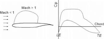
Typical flat upper surface with aft camber for rear loading Figure 3.22. Transonic flow (supercritical Whitcomb aerofoil)

remains subsonic. In this case, the aerofoil is said to be in transonic flow. At higher angles of attack, transonic effects can appear at lower flight speeds. Aerofoil – thickness distribution along the chord length is the parameter that affects the induc­tion of transonic flow. Transonic characteristics exhibit an increase in wave drag (i. e., the compressibility effect; refer to aerodynamic textbooks). These effects are undesirable but unavoidable; however, aircraft designers keep the transonic effect to a minimum. Special attention is necessary in generating the aerofoil section design, which shows a flatter upper surface. Figure 3.22 depicts a typical transonic aerofoil (i. e., the Whitcomb section) and its characteristics.

The Whitcomb section, which appeared later, advanced the flight speed by min­imizing wave drag (i. e., the critical Mach-number effects); therefore, it is called the supercritical aerofoil section. The geometrical characteristics exhibit a round LE, followed by a flat upper surface and rear-loading with camber; the lower surface at the trailing edge shows the cusp. All modern high-subsonic aircraft have the super­critical aerofoil section characteristics. Manufacturers develop their own section or use any data available to them.

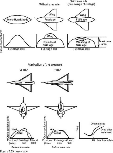
For an aircraft configuration, it has been shown that the cross-sectional area dis­tribution along the body axis affects the wave drag associated with transonic flow. The bulk of this area distribution along the aircraft axis comes from the fuselage and the wing. The best cross-sectional area distribution that minimizes wave drag is a cigar-like smooth distribution (i. e., uniform contour curvature; lowest wave drag) known as the Sears-Haack ideal body (Figure 3.23). The fuselage shape approxi­mates it; however, when the wing is attached, there is a sudden jump in volume dis­tribution (Figure 3.23). In the late 1950s, Whitcomb demonstrated through exper­iments that “waisting” of the fuselage in a “coke-bottle” shape could accommo­date wing volume, as shown in the last of Figure 3.23. This type of procedure for wing-body shaping is known as the area rule. A smoother distribution of the cross­sectional area reduces wave drag.

Whitcomb’s finding was deployed on F102 Delta Dragger fighter aircraft (see Figure 3.23). The modified version with area ruling showed considerably reduced transonic drag (see Figure 4.29). For current designs with wing-body blending, it is less visible, but designers still study the volume distribution to make it as smooth as possible. Even the hump of a Boeing 747 flying close to transonic speed helps with the area ruling. The following subsection considers wing (i. e., 3D body) aerodynamics.

Transonic Effects - Area Rule

High-Lift Devices

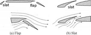
High-lift devices are small aerofoil-like elements that are fitted at the trailing edge of the wing as a flap and/or at the LE as a slat (Figures 3.20a and b). In typical cruise conditions, the flaps and slats are retracted within the contour of the aerofoil. Flaps and slats can be used independently or in combination. At low speed, they are deflected about a hinge line, rendering the aerofoil more curved as if it had more camber. A typical flow field around the flaps and slats is shown in Figure 3.20. The entrainment effect through the gap between the wing and the flap allows flow to remain attached in order to provide the best possible lift.

Designation

Diagram

C‘rw,

a

et Cxmas (degrees)

4d

<4e

Reference

NACA

Basic aerofoil Clark Y

1.29

15

7.5

-.085

TN 459

.30o

Plain flap deflected 45®

‘=’4

1.95

12

4.0

TR 427

,30c

Slotted flap deflected 46s

1.98

12

4.0

TR 427

.30o

Split flap deflected 45q

2.16

14

4.3

-0.250

TN 422

.300 hinged at.80c Split flap (Zap) deflected 45°

C=====:^

2.26

13

4.43

—0.300

TN 422

.300 hinged at.900 Split flap (Zap) deflected 45°

2.32

12.5

4.45

-0.385

TN 422

.300

Fowler flop deflected 40°

X

2.82

13

4.55

—0.660

TR 534

.400

Fowler flap deflected 40°

X

3.09

14

4.1

—0.860

TR 534

Fixed slot

1.77

t

24

5.35

TR 427

Handley Page automatic slot

1.84

28

4.1

TN 459

Fixed elot end,30c plain flap deflected 45°

*=4

2.18

19

3.7

TR 427

Fixed slot and.30c slotted – flap deflected 45°

*=4

2.26

18

3.77

TR 427

Handley Page «lot and.40c Fowler flap deflected 40°

3.36

16

3.7

-0.740

TN 459

Figure 3.21. High-lift devices

High-Lift Devices

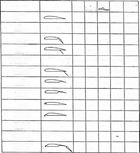
Considerable lift enhancement can be obtained by incorporating high-lift devices at the expense of additional drag and weight. Figure 3.21 lists the experi­mental values of the incremental lift coefficients of the Clark Y aerofoil. These val­ues are representative of other types of NACA aerofoils and may be used if actual data are not available.

Higher-performance, high-lift devices are complex in construction and there­fore heavier and more expensive. Selection of the type is based on cost-versus – performance trade-off studies – in practice, past experience is helpful in making selections.

Comparison of Three NACA Aerofoils

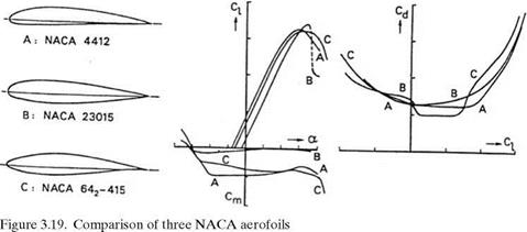
The NACA 4412, NACA 23015, and NACA 642-415 are three commonly used aerofoils – there are many different types of aircraft that use one of these aerofoils. Figure 3.19 shows their characteristics for comparison purposes.

The NACA 23015 has sharp stalling characteristics; however, it can give a higher sectional lift, C/, and lower sectional moment, Cm, than others. Drag-wise, the NACA 642-415 has a bucket to give the lowest sectional drag. The NACA 4412 is the oldest and, for its time, was the favorite. Of these three examples, the NACA 642­415 is the best for gentle stall characteristics and low sectional drag, offsetting the small amount of trim drag due to the relatively higher moment coefficient. Designers

Figure 3.20. Flap and slat flow field (see Figure 3.43 for slat and flap effects)

Comparison of Three NACA Aerofoilsmust choose from a wide variety of aerofoils or generate one suitable for their pur­poses.

Designers look for the following qualities in the characteristics of a 2D aerofoil:

1. The lift should be as high as possible; this is assessed by the CLmax of the test results.

2. The stalling characteristics should be gradual; the aerofoil should able to main­tain some lift past CLmax. Stall characteristics need to be assessed for the applica­tion. For example, for ab initio training, it is better to have aircraft with forgiv­ing, gentle stalling characteristics. For aircraft that will be flown by experienced pilots, designers could compromise with gentle stalling characteristics and bet­ter performance.

3. There should be a rapid rise in lift; that is, a better lift-curve slope given by dCL/da.

4. There should be low drag using a drag bucket, retaining flow laminarization as much as possible at the design CL (i. e., angle of incidence).

5. Cm characteristics should give nose-down moments for a positively cambered aerofoil. It is preferable to have low Cm to minimize trim drag.

An aerofoil designer must produce a suitable aerofoil that encompasses the best of all five qualities – a difficult compromise to make. Flaps are also an integral part of the design. Flap deflection effectively increases the aerofoil camber to generate more lift. Therefore, a designer also must examine all five qualities at all possible flap and slat deflections.

From this brief discussion, it is apparent that aerofoil design itself is state of the art and is therefore not addressed in this book. However, experimental data on suitable aerofoils are provided in Appendix C.

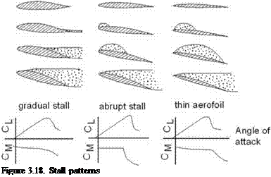
Gradual Stall

This is a desirable pattern and occurs when separation is initiated at the trailing edge of the aerofoil; the remainder maintains the pressure differential. As the separation moves slowly toward the LE, the aircraft approaches stall gradually, giving the pilot enough time to take corrective action. The forgiving and gentle nature of this stall is ideal for an ab initio trainee pilot. The type of aerofoil that experiences this type of stall has a generously rounded LE, providing smooth flow negotiation but not necessarily other desirable performance characteristics.

3.7.1 Abrupt Stall

This type of stall invariably starts with separation at the LE, initially as a small bubble. Then, the bubble either progresses downstream or bursts quickly and catastrophically (i. e., abruptly). Aerofoils with a sharper LE, such as those found on higher-performance aircraft, tend to exhibit this type of behavior.

Aircraft stall is affected by wing stall, which depends on aerofoil characteristics. Section 3.19 addresses wing stall (see Figure 3.40).

Types of Stall

Подпись: Figure 3.18. Stall patterns

Section 3.3 describes the physics of stall phenomena over an aerofoil. It is essential that designers understand stalling characteristics because wing stall is an undesir­able state for an aircraft to enter. Figure 3.18 shows the general types of stall that

Types of Stall

can occur. This section describes how these different types of stall affect aircraft design.

Generation of Lift

Figure 3.12 is a qualitative description of the flow field and its resultant forces on the aerofoil. The result of skin friction is the drag force, shown in Figure 3.12b. The lift is normal to the flow.

Section 3.5 explains that a typical aerofoil has an upper surface more curved than the lower surface, which is represented by the camber of the aerofoil. Even for a symmetrical aerofoil, the increase in the angle of attack increases the velocity at the upper surface and the aerofoil approaches stall, a phenomenon described in Section 3.10.

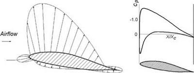
Figure 3.13a shows the pressure field around the aerofoil. The pressure at every point is given as the pressure coefficient distribution, as shown in Figure 3.13b. The upper surface has lower pressure, which can be seen as a negative distribution. In addition, cambered aerofoils have moments that are not shown in the figure.

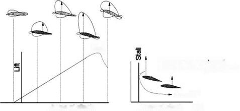
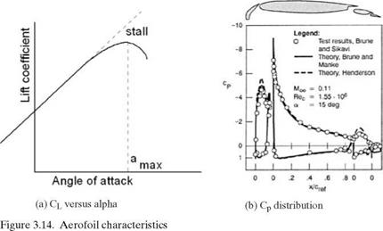
Figure 3.14a shows the typical test results of an aerofoil as plotted against a variation of the angle of attack, a. Initially, the variation is linear; then, at about 10 deg a, it starts to deviate and reaches maximum Cl (Cimax at amax). Past amax, the Cl drops rapidly – if not drastically – when stall is reached. Stalling starts at reaching amax. These graphs show aerofoil characteristics. Figure 3.14b depicts the corresponding distribution of the pressure coefficient Cp at an angle of attack of 15 deg.

Deflection of either the control surface or a change in the angle of attack will alter the pressure distribution. The positive Y-direction has negative pressure on the upper surface. The area between the graphs of the upper and lower surface Cp distribution is the lift generated for the unit span of this aerofoil.

Figure 3.15 shows flow physics around the aerofoil. At the LE, the streamlines move apart: One side negotiates the higher camber of the upper surface and the other side negotiates the lower surface. The higher curvature at the upper surface generates a faster flow than the lower surface. They have different velocities when they meet at the trailing edge, creating a vortex sheet along the span. The phe­nomenon can be decomposed into a set of straight streamlines representing the

Generation of Lift

Generation of Liftfree streamflow condition and a set of circulatory streamlines of a strength that matches the flow around the aerofoil. The circulatory flow is known as the circu­lation of the aerofoil. The concept of circulation provides a useful mathematical formulation to represent lift. Circular flow is generated by the effect of the aerofoil camber, which gives higher velocity over the upper wing surface. The directions of the circles show the increase in velocity at the top and the decrease at the bottom, simulating velocity distribution over the aerofoil.
The flow over an aerofoil develops a lift per unit span of l = pUr (see other textbooks for the derivation). Computation of circulation Г is not easy. This book uses accurate experimental results to obtain the lift.

The center of pressure, cp, is the point through which the resultant force of the pressure field around the body acts. For an aerofoil, it moves forward as the angle of attack is increased until stall occurs as a degenerate case (Figure 3.16).

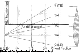
The aerodynamic center, ac, is concerned with moments about a point, typically on the chord line (Figures 3.17). The relationship between the moment and the angle of attack depends on the approximate point at which the moment is taken. However, at the quarter-chord point (there could be minor variations among aerofoils but they

Stall

Locus of Cp moving aft

with reduced angle of attack

Подпись: Angle of attack Подпись: Angle of attack Подпись: low

toward ТЕ

Figure 3.16. Movement of center of pressure with change in lift

Figure 3.17. Aerodynamic center – in­variant near quarter-chord

Подпись: (Fractional chord position about which moment is taken) are ignored in this book), it is noticed that the moment is invariant to the angle of attack until stall occurs. This point at the quarter chord is called the ac, which is a natural reference point through which all forces and moments are defined to act. The ac offers much useful information that is discussed later.
The higher the positive camber, the more lift is generated for a given angle of attack; however, this leads to a greater nose-down moment. To counter this nose – down moment, conventional aircraft have a horizontal tail with the negative camber supported by an elevator. For tailless aircraft (e. g., delta wing designs in which the horizontal tail merges with the wing), the trailing edge is given a negative camber as a “reflex.” This balancing is known as trimming and it is associated with the type of drag known as trim drag. Aerofoil selection is then a compromise between having good lift characteristics and a low moment.

Definitions of Aerodynamic Parameters

Section 3.4 defines Re and describes the physics of the laminar/turbulent boundary layer. This section provides other useful nondimensional coefficients and derived parameters frequently used in this book. The most common nomenclature – without any conflicts on either side of the Atlantic – are listed here; it is internationally understood.

Let q2 = 1/2p V2 = dynamichead (3.21)

(The subscript 2 represents the free streamflow condition and is sometimes omitted.) ‘q’ is a parameter extensively used to nondimensionalize grouped param­eters.

The coefficients of the 2D aerofoil and the 3D wing differ, as shown here (the lowercase subscripts represent the 2D aerofoil and the uppercase letters are for the 3D wing).

2-D aerofoil section (subscripts with lowercase letters):

Cl = sectional aerofoil-lift coefficient = section lift/qc Cd = sectional aerofoil-drag coefficient = section drag/qc (3 )

Cm = aerofoil pitching-moment coefficient ^ ‘

= section pitching moment/qc2(+ nose up)

3D wing (subscripts with uppercase letters), replace chord, c by wing area, SW:

CL = lift coefficient = lift/qSW

CD = drag coefficient = drag/qSW (3.23)

CM = pitching-moment coefficient = lift/qSW(+ nose up)

Section 3.14 discusses 3D wings, where correction to the 2D results is necessary to arrive at 3D values. Figure 3.13 shows the pressure distribution at any point over the surface in terms of the pressure coefficient, Cp, which is defined as follows:

Definitions of Aerodynamic Parameters

Other Types of Aerofoils

After the six-series sections, aerofoil design became more specialized with aerofoils designed for their particular application. In the mid-1960s, Whitcomb’s “supercrit­ical” aerofoil allowed flight with high critical Mach numbers (operating with com­pressibility effects, producing in wave drag) in the transonic region. The NACA seven and eight series were designed to improve some aerodynamic characteristics. In addition to the NACA aerofoil series, there are many other types of aerofoils in use.

To remain competitive, the major industrial companies generate their own aero­foils. One example is the peaky-section aerofoils that were popular during the 1960s and 1970s for the high-subsonic flight regime. Aerofoil designers generate their own purpose-built aerofoils with good transonic performance, good maximum lift capability, thick sections, low drag, and so on – some are in the public domain but most are held commercial in confidence for strategic reasons of the organiza­tions. Subsequently, more transonic supercritical aerofoils were developed, by both research organizations and academic institutions. One such baseline design in the United Kingdom is the RAE 2822 aerofoil section, whereas the CAST 7 evolved in Germany. It is suggested that readers examine various aerofoil designs.

The NASA General Aviation Wing (GAW) series evolved later for low-speed applications and use by general aviation. Although the series showed better lift-to – drag characteristics, their performance with flaps deployment, tolerance to produc­tion variation, and other issues are still in question. As a result, the GAW aerofoil has yet to compete with some of the older NACA aerofoil designs. However, a modified GAW aerofoil has appeared with improved characteristics. Appendix D provides an example of the GAW series aerofoil.

Often, a wing design has several aerofoil sections varying along the wing span (Figure 3.12). Appendix D provides six types of aerofoil [4] for use in this book. Readers should note that the 2D aerofoil wind-tunnel test is conducted in restricted conditions and will need corrections for use in real aircraft (see Section 3.12).

Other Types of Aerofoils

(a) Pressure field distribution (b) Cp distribution over aerofoil

Figure 3.13. Pressure field representations around aerofoil

NACA Five-Digit Aerofoil

After the four-digit sections came the five-digit sections. The first two and the last two digits represent the same definitions as in the four-digit NACA aerofoil. The middle digit represents the aft position of the mean line, resulting in the change in the defining camber line curvature. The middle digit has only two options: 0 for a straight and 1 for an inverted cube. The NACA five-digit aerofoil has more curva­ture toward the LE. Following are the examples of the NACA 23015 and NACA 23115:

2 3 0 or 1 15

Maximum camber Maximum thickness of 0: straight, the last two digits

position in % maximum camber in 1: inverted are maximum t/c

chord 1/10 of chord cube ratio in % of chord

NACA Six-Digit Aerofoil

The five-digit family was an improvement over the four-digit NACA series aerofoil; however, researchers subsequently found better geometric definitions to represent a new family of a six-digit aerofoil. The state-of-the-art for a good aerofoil often follows reverse engineering – that is, it attempts to fit a cross-sectional shape to a given pressure distribution. The NACA six-digit series aerofoil came much later (it was first used for the P51 Mustang design in the late 1930s) from the need to gener­ate a desired pressure distribution instead of being restricted to what the relatively simplistic four – and five-digit series could offer. The six-digit series aerofoils were generated from a more or less prescribed pressure distribution and were designed to achieve some laminar flow. This was achieved by placing the maximum thick­ness far back from the LE. Their low-speed characteristics behave like the four – and five-digit series but show much better high-speed characteristics. However, the drag bucket seen in wind-tunnel test results may not show up in actual flight. Some of the six-digit aerofoils are more tolerant to production variation as compared to typical five-digit aerofoils.

The definition for the NACA six-digit aerofoil example 632-212 is as follows:

6

3

Subscript 2

2

12

Six series

Location of

Half width of

Ideal Cl in

Maximum

minimum Cp in

low drag bucket

tenths

thickness in

1/10 chord

in 1/10 of Ci

(design)

% of chord

NACA Five-Digit Aerofoil

(a) Streamline pattern over aerofoil (b) Resultant force on aerofoil

Figure 3.12. Flow field around aerofoil

An example of the NACA 653-421 is a six-series airfoil for which the minimum pressure’s position is in tenths of a chord, indicated by the second digit (at the 50% chord location). The subscript 3 indicates that the drag coefficient is near its min­imum value over a range of lift coefficients of 0.3 above and below the design lift coefficient. The next digit indicates the design lift coefficient of 0.4, and the last two digits indicate the maximum thickness in percent chord of 21% [4].

Groupings of Aerofoils and Their Properties

From the early days, European countries and the United States undertook inten­sive research to generate better aerofoils to advance aircraft performance. By the 1920s, a wide variety of aerofoils appeared and consolidation was needed. Since the 1930s, NACA generated families of aerofoils benefiting from what was available in the market and beyond. It presented the aerofoil geometries and test results in a systematic manner, grouping them into family series. The generic pattern of the NACA aerofoil family is listed in [4] with well-calibrated wind-tunnel results. The book was published in 1949 and has served aircraft designers (civil and military) for more than a half-century and is still useful. Since its publication, research to generate better aerofoils for specific purposes continued, but they are made in the industry and are “commercial in confidence.”

Designations of the NACA series of aerofoils are as follows: the four-digit, the five-digit, and the six-digit, given herein. These suffice for the purposes of this book – many fine aircraft have used the NACA series of aerofoils. However, brief com­ments on other types of aerofoils are also included. The NACA four – and five-digit aerofoils were created by superimposing a simple camber-line shape with a thick­ness distribution that was obtained by fitting with the following polynomial [4]:

y = ± (t/0.2) x (0.2969 x x0 5 – 0.126 x x – 0.3537 x x[1] + 0.2843

x x[2] – 0.1015 x x[3]) (3.20)

NACA Four-Digit Aerofoil

Each of the four digits of the nomenclature represents a geometrical property, as explained here using the example of the NACA 2315 aerofoil:

Groupings of Aerofoils and Their Properties

Figure 3.11. Camber line distribution

The camber line of four-digit aerofoil sections is defined by a parabola from the LE to the position of maximum camber followed by another parabola to the trailing edge (Figure 3.11). This constraint did not allow the aerofoil design to be adaptive. For example, it prevented the generation of an aerofoil with more curvature toward the LE in order to provide better pressure distribution.