Category AIRCRAF DESIGN

Comparison between Civil and Military Aircraft Design Requirements

This section compares the civil and military aircraft design classes, as shown in Table 2.2.

Once the configuration is finalized, the governing equations for sizing, engine matching, and performance analysis are the same for all categories (although drag estimation presents some difficulty for complex configurations, especially supersonic designs). The crux of a military aircraft design is systems integration for survivabil­ity, maneuver control (i. e., FBW), target acquisition, weapons management, navi­gation (i. e., unknown terrain), and communication strategies (e. g., identification of friend or foe). Military aircraft design is very different compared to civil aircraft design. A major aspect of combat aircraft design is the systems architecture for threat analysis and survivability – without these in the combat aircraft design of the Eurofighter Typhoon or the F22 Raptor class, any coursework exercise is meaning­less. Military certification standards are more elaborate and time consuming. These crucial issues are not within the scope of this book – only a few specialist books are available that address systems architecture for threat analysis and survivability – and

Table 2.3. FAR categories of airworthiness standards

Aircraft types

General

Normal

Transport

Aircraft

FAR Part 23

FAR Part 23

FAR Part 25

Engine

FAR Part 33

FAR Part 33

FAR Part 33

Propeller

FAR Part 35

FAR Part 35

FAR Part 35

Noise

FAR Part 36

FAR Part 36

FAR Part 36

General operations

FAR Part 91

FAR Part 91

FAR Part 91

Agriculture

FAR Part 137

Large commercial transport

Not applicable

Not applicable

FAR Part 121

some of those are obviously confidential. However, seminars on these topics are offered to those who are well versed in aircraft design.

The simpler case of an AJT in subsonic operation provides an idea of military aircraft design, although the author would not apply the certification regulations as extensively as in the civil aircraft examples for reasons discussed previously. It is possible that the CAS version of the AJT could become supersonic in a shallow dive.

Military Market

This extended section of the book can be found on the Web at www. cambridge .org/Kundu and describes the typical military aircraft aviation market, starting with compliance with national defense requirements (MoD).

1.6.1 Aircraft Specifications/Requirements for Military Aircraft Case Studies

This extended section of the book can be found on the Web at www. cambridge .org/Kundu and outlines specifications for introductory classroom work on military aircraft design (e. g., the Advanced Jet Trainer).

Table 2.2. Comparison between civil and military aircraft design requirements

Issue

Civil aircraft

Military aircraft

Design space

Verified

Aspirational

Certification standards

Civil (FAR-U. S.)

Military (Milspecs – U. S.)

Operational environment

Friendly

Hostile

safety issues

Uncompromised, no ejection

Survivability requires ejection

Mission profile

Routine and monitored by air

As situation demands and could

traffic control (ATC)

be unmonitored

Flight performance

Near-steady-state operation and

Large variation in speed and

scheduled; gentle maneuvers

altitudes; pilot is free to change briefing schedule; extreme

maneuvers

Flight speed

Subsonic and scheduled (not

Have supersonic segments; in

addressing SST here)

combat, unscheduled

Engine performance

Set throttle dependency,

Varied throttle usage,

no afterburner (subsonic)

with afterburner

Field performance

Mostly metal runways, generous

Different surfaces with restricted

in length, with ATC support

lengths; marginal ATC

Systems architecture

Moderately complex,

Very complex,

high redundancies,

lower redundancies,

no threat analysis

threat acquisition

Environmental issues

Strictly regulated; legal minimum

Relaxed; peacetime operation in

standards

restricted zones

Maintainability

High reliability with low

High reliability but at a

maintenance cost

considerably higher cost

Ground handling

Extensive ground-handling

Specialized and complex

support with standard equipment

ground-support equipment

Economics

Minimize DOC; cash flow back

Minimize LCC; no cash

through revenue earned

flow back

Training

Routine

Specialized and more complex

Aircraft Specifications and Requirements for Three Civil Aircraft Case Studies

It is recommended that the introductory coursework exercise use one of the three specifications provided as a starting point. Accordingly, the initial follow-up activ­ity is limited to work on the Learjet 45 class aircraft (see the second design speci­fication).

Подпись:4 passengers (including pilot) + baggage (e. g.,
Подпись:2 golf bags) = 4 x 85 (averaged) + 60 = 400 kg 800 miles + reserve Above 200 mph

Unpressurerized cabin; approximately 10,000 ft (ceiling could be higher)

500 m @ sea level to 35 ft

500 m (at takeoff weight) @ sea level from 50 ft

8 meters per second (m/s)

Retractable

Cabin heating, side-by-side seating, cabin interior width = 50 in.

Conventional Piston engine

DERIVATIVE VERSION AS A LIGHTER TWO-SEATER LIGHT CLUB TRAINER/USAGE aircraft (far 23). (Derivatives are more difficult to develop for smaller aircraft because there is less room with which to work. Fuselage unplugging is difficult unless

the baseline design made provision for it. There are considerable savings in certifi­cation cost.)

Подпись:2 passengers plus light baggage = 200 kg 400 miles + reserve 140 mph

300 m @ sea level to 35 ft 300 m (at takeoff weight) @ sea level from 50 ft 5 m/s Fixed

Cabin heating, side-by-side seating, cabin interior width = 46 in.

(The other specifications are the same as in the baseline four-seater design.)

Derivative versions are achieved by shortening the wing root and empennage tips, unplugging the fuselage section (which is difficult if it is not a continuous section but is possible if the design of the baseline four-passenger aircraft considers this in adv­ance), lightening the structural members, re-engining to lower the power, and so forth.

Design Specifications of a Baseline Eight – to Ten-Passenger (Learjet 45 Class) Aircraft (FAR 25)
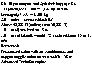
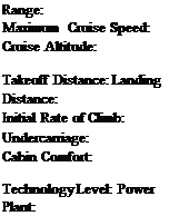
Подпись: 8 to 10 passengers and 2 pilots + baggage 8 x 100 (averaged) + 300 = 1,100 kg 10 x 80 (averaged) + 300 = 1,100 kg 2.0 miles + reserve Mach 0.7 Above 40,000 ft (ceiling over 50,000 ft) 1.0 m @ sea level to 15 m 1.0 m (at takeoff weight) @ sea level from 15 m 16 m/s Retractable Pressurized cabin with air-conditioning and oxygen supply, cabin interior width = 58 in. Advanced Turbofan engine Payload:

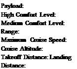
High Comfort Level:

Medium Comfort Level:

Range:

Maximum Cruise Speed:

Cruise Altitude:

Takeoff Distance:

Landing Distance:

Initial Rate of Climb:

Undercarriage:

Cabin Comfort:

Technology Level: Power Plant:

SHORTENED DERIVATIVE VERSION: FOUR TO SIX PASSENGERS IN A BASELINE AIRCRAFT FAMILY (FAR 25). (This derivative works by unplugging continuous-section fuselage barrel on both sides of the wing.)
Подпись:4 to 6 passengers and 2 pilots + baggage 4 x 100 (averaged) + 200 = 600 kg 6 x 80 (averaged) + 120 = 600 kg 2,000 miles + reserve Mach 0.7

Above 40,000 ft (ceiling over 50,000 ft)

800 m @ sea level to 15 m

800 m (at takeoff weight) @ sea level from 15 m

(The other specifications are the same as in the baseline design.)

LENGTHENED DERIVATIVE VERSION: TWELVE TO FOURTEEN PASSENGERS IN THE

baseline aircraft family (far 25). (The longer derivative works in the same way by inserting continuous-section fuselage plugs on both sides of the wing.)

Payload: 12 to 14 passengers and 2 pilots + baggage

High Comfort Level: 12 x 100 (averaged) + 300 = 1,500 kg

Medium Comfort Level: 14 x 80 (averaged) + 380 = 1,500 kg

Range: 2,000 miles + reserve

Takeoff Distance: 1,200 m @ sea level to 15 m

Landing Distance: 1,200 m (at takeoff weight) @ sea level from 15 m

(The other specifications are the same as in the baseline design.)

Design Specifications of a Baseline 150-Passenger (Airbus 320 Class) Aircraft (FAR 25)
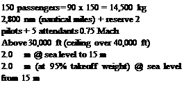
Подпись: 150 passengers = 90 x 150 = 14,500 kg 2,800 nm (nautical miles) + reserve 2 pilots + 5 attendants 0.75 Mach Above 30,000 ft (ceiling over 40,000 ft) 2.0 m @ sea level to 15 m 2.0 m (at 95% takeoff weight) @ sea level from 15 m Payload:

Range:

Crew:

Maximum Cruise Speed:

Cruise Altitude:

Takeoff Distance:

Landing Distance:

Подпись:Подпись:14 m/s Retractable

Pressurized cabin with air conditioning and oxygen supply, cabin interior diameter = 144 in.

Advanced Turbofan engine

DERIVATIVE VERSION IN THE AIRCRAFT FAMILY (TYPICALLY AIRBUS 319 AND AIRBUS 321 CLASS ON BOTH SIDES OF THE BASELINE AIRBUS 320 AIRCRAFT). This is accomplished by plugging and unplugging the fuselage as in a Bizjet design. Readers are referred to Jane’s All the World’s Aircraft for derivative details and Appendix D for an exam­ple. Wide-body aircraft design follows the methodology.

(Note: The author encourages readers to explore market surveys for other classes of aircraft. To diversify, following are brief specifications for two interest­ing examples [7]).

A. Agriculture Applications Aircraft

1. Airframe must be highly corrosion resistant.

2. Airframe must be easily cleaned (i. e., removable side panels).

3. Airframe must be flushed with water after last flight.

4. Airframe must be easily inspected.

5. Airframe must be easily repaired.

6. Airframe must be highly damage tolerant.

7. Dry and wet chemicals must be loaded easily and quickly.

8. Cockpit must have excellent pilot crash protection.

9. Pilot must have excellent visibility (i. e., flagman, ground crew, and obstacles).

10. The stall speed must be 60 knots or less.

11. The service ceiling is 15,000 ft.

12. Takeoff performance: 20,000-ft field length (rough field) with 50-ft obstacles.

13. Hopper capacity: 400 U. S. gallons/3,200 lbs.

It is suggested that the design be approached through use of FAR Parts 137,135, and 123. Readers may review current designs from Jane’s All the World’s Aircraft. Key considerations include choice of materials, configuration and structural layout, and systems design. In every other respect, the design should follow the standard approach described herein.

B. Airport Adaptive Regional Transport with Secondary Role to Support U. S. Home­land Security (Abridged from [7])

Payload: 49 passengers + flight and cabin crew

Range: 1,500 miles with reserve

Takeoff and Landing 2,500 ft

Field Length:

Maximum Speed: 400 knots

Mission Profile: Multiple takeoffs and landings without refueling

For the airport adaptive role, the aircraft can simultaneously approach a major air­port in noninterfering adverse weather and takeoff and land from shorter, largely unused runways, subrunways, and taxiways. The aircraft will be evaluated for an automatic spiral-descending, decelerating approach in instrument meteorological conditions (IMC) (Category 3C) conditions and be able to continue with one engine inoperative. The aircraft also has the following secondary roles:

• Serve the civil reserve fleet and be available during a homeland-security crisis

• Serve as an ambulance

• Serve as transport firefighters to remote wilderness areas

• Serve as an emergency response vehicle for urban terrorism or a natural disaster by changing passenger-accommodation fitment

The aircraft will have half of the payload and a 750-mile range into makeshift land­ing zones of at least 1,000 ft.

More information is required for the specifications, but the level of technology is not within the scope of this book.

Other than drag estimation and certification regulations (e. g., noise), the SST design is similar to subsonic transport, aircraft design methodology. Supersonic drag estimation is addressed in Chapter 9.

Civil Aircraft Market

Following up on the review in Chapter 1, about the current status of the civil aircraft market, this section describes how to generate aircraft specifications that will help to sell the product and generate a profit. The coursework starts here with a mock (i. e., representative) market survey leading to what must be designed – that is, the conception of the aircraft, the Phase 1 obligations.

Input from operators to manufacturers is significant and varied. The manu­facturer needs to group the requirements intelligently in a family of aircraft sizes and capabilities. It is necessary to cover as much ground as the market demands yet maintain component commonalities in order to lower development costs of the derivative aircraft in the family. This book lists only those market parameters that affect aircraft aerodynamic design, the most important being the payload-range capability of the aircraft, which has the greatest influence in shaping the aircraft. Details of other requirements (e. g., systems requirements, maintenance, and pas­senger services) are not discussed here but are briefly introduced.

For the mock market studies, students may be asked to table aircraft require­ments as if they are representing the airlines’ interest. It is understandable that due to inexperience, they may list requirements that are not practicable. It is therefore the instructor’s responsibility to provide reasons for discarding each impracticable point and then coalesce the remainder into a starting point. Section 2.7.1 suggests interesting cases for coursework experience. There is a wide variety of civil aircraft in operation; following are requirements for the three classes addressed in the scope of this book.

Military Aircraft and Its Component Configurations

This extended section of the book can be found on the Web at www. cambridge .org/Kundu and depicts typical military aircraft components, with Figure 2.4 depict­ing an exploded view of an F16-type aircraft configuration.

Figure 2.4. Military aircraft configuration

Figure 2.5. A diagram of the General Dynamics (now Boeing) F16

1.6 Market Survey

In a free market economy, an industry cannot survive unless it grows; in a civil – market economy, governmental sustenance is only a temporary relief. The starting point to initiate a new aircraft design project is to establish the key drivers – that is, the requirements and objectives based on market, technical, certification, and organizational requirements. These key drivers are systematically analyzed and then documented by aircraft manufacturers (Chart 2.6).

In several volumes, documents that describe details of the next tier of design specifications (i. e., requirements) are issued to those organizations involved with

Military Aircraft and Its Component Configurations

Подпись:

Подпись: Regulatory Drivers (from government) Подпись: Technology Drivers (from industries)

Chart 2.6. The design drivers (in a free market economy, it faces competition)

a project. A market survey is one way to determine customer requirements – that is, user feedback guides the product. In parallel, the manufacturers incorporate the latest but proven technologies to improve design and stay ahead of the competition, always restricted by the financial viability of what the market can afford. Continual dialogue among manufacturers and operators results in the best design.

Military aircraft product development has a similar approach but requires mod­ifications to Chart 2.6. Here, government is both the single customer and the regu­latory body; therefore, competition is only among the bidding manufacturers. The market is replaced by the operational requirements arising from perceived threats from potential adversaries. Column 1 of Chart 2.6 becomes “operational drivers” that includes weapons management, counterintelligence, and so on. Hence, this sec­tion on the market survey is divided into civilian and military customers, as shown in Chart 2.7. Customer is a broad term that is defined in this book as given in the chart.

In the U. K. military, the Ministry of Defense (MoD), as the single customer, searches for a product and circulates a Request for Proposal (RFP) to the national infrastructure, where most manufacturing is run privately. It is similar in the United States using different terminology. The product search is a complex process – the MoD must know a potential adversary’s existing and future capabilities and admin­istrate national research, design, and development (RD&D) infrastructures to be ready with discoveries and innovations to supersede an adversary’s capabilities.

Подпись:

Military Aircraft and Its Component Configurations Подпись: Military Customer t Ministry of Defense (Single) t

Customer of Aircraft

Chart 2.7. Customers of aircraft manufacturer

The Air Staff Target (AST) is an elaborate aircraft specification as a customer requirement. A military project is of national interest and, in today’s practice, capa­ble companies are invited to first produce a technology demonstrator as proof of concept. The loser in the competition is paid by the government for the demon­strator and learns about advanced technology for the next RFP or civilian design. Therefore, in a sense, there is no loser, and the nation hones its technical manpower.

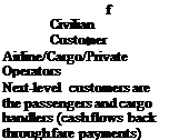
Although it is used, the author does not think an RFP is appropriate terminol­ogy in civilian applications: Who is making the request? It is important for aircraft manufacturers to know the requirements of many operators and supply a product that meets the market’s demands in performance, cost, and time frame. Airline, cargo, and private operators are direct customers of aircraft manufacturers, which do not have direct contact with the next level of customers (i. e., passengers and cargo handlers) (see Chart 2.7). Airlines do their market surveys of passenger and freight requirements and relay the information to manufacturers. The surveys often are established by extensive studies of target-city pairs, current market coverage, growth trends, and passenger input. Inherent in the feedback are diverse require­ments that must be coalesced into a marketable product. A major order from a single operator could start a project, but manufacturers must cater to many oper­ators to enlarge and stabilize their market share. The civilian market is searched through a multitude of queries to various operators (i. e., airlines), both nationally and internationally. In civil aviation, the development of the national infrastructure must be coordinated with aircraft manufacturers and operators to ensure national growth. Airlines generate revenue by carrying passengers and freight, which provide the cash flow that supports the maintenance and development of the civil aviation infrastructure. Cargo generates important revenues for airlines and airports, and the market for it should not be underestimated – even if it means modifying older airplanes. Manufacturers and operators are in continual contact to develop product lines with new and/or modified aircraft. Aircraft manufacturers must harmonize the diversity in requirements such that management decides to undertake a conceptual study to obtain the go-ahead. There is nothing comparable to the process taken by the MoD to initiate an RFP with a single customer demand.

The private or executive aircraft market is driven by operators that are closely connected to business interests and cover a wide spectrum of types, varying from four passengers to specially modified midsized jets.

Military aircraft utilization in peacetime is approximately 7,500 hours, about one-tenth that of commercial transport aircraft (i. e., « 75,000 hours) in its lifespan. Annual peacetime military aircraft utilization is low (i. e.,« 600 hours) compared to annual civil aircraft utilization, which can exceed 3,000 hours.

Civil Aircraft and Its Component Configurations

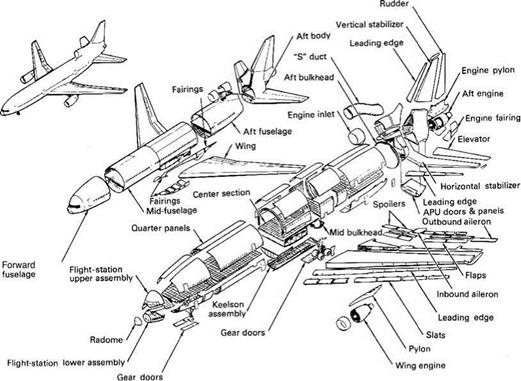
In general, the civil aircraft category includes five types: (1) small club trainers, (2) utility aircraft, (3) business aircraft, (4) narrow-body commercial transporters (regional aircraft to midsize), and (5) wide-body large transporters. The various types of available configuration options are described in Chapter 4. The aircraft components shown in Figure 2.3 are some of the obvious ones (e. g., wing, fuselage, nacelle, and empennage); others (e. g., winglets, strakes, and auxiliary control sur­faces) are less obvious but play vital roles – otherwise, they would not be included. Because there are many options, components are associated in groups for conve­nience, as described in the following subsections (refer to Figure 2.3).

Civil Aircraft and Its Component Configurations

Figure 2.3. Lockheed 1011 diagram (courtesy of Michael Niu [10])

Fuselage Group

This group includes the nose cone, the constant midsection fuselage, the tapered aft fuselage, and the tail cone. The fuselage belly fairing (shown in Figure 2.3 as several subassembly components below the fuselage) may be used to house equipment at the wing-fuselage junction, such as the undercarriage wheels.

Wing Group

This group consists of the main wing, high-lift devices, spoilers, control surfaces, tip devices, and structural wing box that passes through the fuselage. High-lift devices include leading-edge slats or trailing-edge flaps. In Figure 2.3, the leading-edge slats are shown attached to the main wing and the trailing-edge flaps and spoilers are shown detached from the port wing. Spoilers are used to decelerate aircraft on descent; as the name suggests, they “spoil” lift over the wing and are useful as “lift dumpers” on touchdown. This allows the undercarriage to more rapidly absorb the aircraft’s weight, enabling a more effective application of the brakes. In some air­craft, a small differential deflection of spoilers with or without the use of ailerons is used to stabilize an aircraft’s rolling tendencies during disturbances. In Figure 2.3, the wing is shown with winglets at the tip; winglets are one of a set of tip treatments that can reduce the induced drag of an aircraft.

Empennage Group

The empennage is the set of stability and control surfaces at the back of an aircraft. In Figure 2.3, it is shown as a vertical tail split into a fin in the front and a rudder at

the back, with an end cap on the top. The horizontal tail, shown as a T-tail set at the top of the vertical tail, consists of the stabilizer and the elevator. Canard configura­tion has ‘tail’ in front.

Nacelle Group

Podded nacelles are slung under the wings and one is mounted on the aft fuselage; pylons affect the attachment. Engines can be mounted on each side of the fuselage. The nacelle design is discussed in detail in Chapter 10. Turbofans are preferred for higher subsonic speed.

Undercarriage Group

The undercarriage, or landing gear, usually consists of a nose-wheel assembly and two sets of main wheels that form a tricycle configuration. Tail-dragging, bicycle, and even quad configurations are possible, depending on the application of an aircraft. Wheels are usually retracted in flight, and the retraction mechanism and stowage bay comprise part of the undercarriage group. Undercarriage design is discussed in Chapter 7.

Not shown in Figure 2.3 are the trimming surfaces used to reduce control forces experienced by the pilot. During the conceptual phase, these surfaces generally are shown schematically, with size based on past experience. The sizing of trim sur­faces is more appropriate once the aircraft configuration is frozen (i. e., a Phase 2 activity). Trim-surface sizing is accomplished by using semi-empirical relations and is fine-tuned by tailoring the surfaces and areas or adjusting the mechanism during flight trials. In this book, trim surfaces are treated schematically – the main task is to size the aircraft and finalize the configuration in Phase 1. On larger aircraft, pow­ered controls are used; pitch trimmings in conjunction with moving tail planes. A propeller-driven aircraft is preferred for cruise speeds below Mach 0.5.

Aircraft Familiarization

This section introduces generic civil and military aircraft. Geometric definitions rele­vant to aerodynamic considerations are addressed in Chapter 3 and detailed descrip­tions of various types of aircraft and their classification are provided in Chapter 4. A diagram of aircraft with major subassemblies as components is provided herein. Indeed, aircraft design has become highly modular in the interests of the “family” concept, which facilitates low development cost by maintaining a high degree of parts commonality.

Aircraft span, length, and height are currently restricted by the ICAO to 80 m, 80 m, and 80 ft, respectively, for ground handling and storage considerations. The height is in feet but the span and length are in meters; this restriction may change. Section 1.6 highlighted the mix of SI and FPS units in aerospace engineering. In the future, only SI units will be used.

Project Activities for Small Aircraft Design

Typical work content and milestones for a small aircraft project are given here in blocks of time; readers need to expand this in bar chart form (the coursework involved in drawing the Gantt chart may alter the contents of the table, as required). Larger-aircraft design follows similar activities in an expanded scale suited to task obligations.

Phase 1: Conceptual Design (6 Months)

1. Perform the market survey to establish aircraft specifications from customer requirements; information is extracted from year-round exploratory work.

2. Lay out candidate aircraft configurations starting with fuselage, followed by wing, undercarriage, power plant, and so forth.

3. Establish wing parameters because they will acquire prime importance in syn­thesizing aircraft design; the parameters include the wing reference area, aspect ratio, wing sweep, taper ratio, aerofoil thickness-to-chord ratio, wing twist, spar location, flap area, flight control, and wing location with respect to fuselage.

4. Initiate CAD 3D surface modeling.

5. Conduct preliminary CFD analysis to establish pressure distribution and loads on aircraft.

6. Conduct preliminary wind-tunnel tests.

7. Determine preliminary weights and CG estimates.

8. Determine aircraft preliminary drag estimate.

9. Size aircraft and match engine.

10. Establish engine data.

11. Conduct preliminary aircraft and engine performance tests.

12. Freeze the configuration to one aircraft.

13. Lay out internal structures and arrange fuselage interior.

14. Complete mock-up drawings, construction, and initial evaluation.

15. Complete the control system concept layout in CAD.

16. Complete the electrical/avionics systems concept layout in CAD.

17. Complete the mechanical systems concept layout in CAD.

18. Complete the power plant installation concept in CAD.

19. Create a database for materials and parts.

20. Establish a plan for bought-out items and delivery schedule.

21. Plan for outsourcing, if applicable.

22. Provide the preliminary cost projection.

23. Obtain management’s go-ahead.

Phase 2: Project Definition (9 Months)

1. Create integrated and component drawings in CAD.

2. Complete FEM stress analysis of all components (e. g., wing and fuselage).

3. Complete mock-up and final assessment.

4. Complete advanced CFD analysis.

5. Conduct wind-tunnel model testing and CFD substantiation.

6. Conduct flutter analysis.

7. Conduct extensive and final aircraft and engine performance tests.

8. Create detailed part design and issue manufacturing/production drawings in CAD. This follows stress analyses of parts.

9. Perform aircraft stability and control analysis and control-surface sizing.

10. Finalize control system design in CAD.

11. Finalize electrical/avionics system design in CAD.

12. Finalize mechanical system design in CAD.

13. Finalize power plant installation design in CAD.

14. Produce jigs and tool design.

15. Plan for subcontracting, if applicable.

16. Place order for bought-out items and start receiving items.

17. Complete cost analysis.

18. Complete design review.

19. Continue customer dialogue and updating (no change in specifications).

Phase 3: Detailed Design (Product Development) (12 Months)

1. Complete detailed component design in CAD.

2. Complete stress analysis.

3. Complete CFD analysis.

4. Revise to final weights analysis.

5. Complete and issue all production drawings in CAD/CAM.

6. Complete production jigs and tools.

7. Complete parts manufacture and begin aircraft component subassembly.

8. Finish receiving all bought-out items.

9. Complete standards, schedules, and checklists.

10. Finalize ground/flight test schedules.

11. Complete prototype shop status schedules.

12. Revise cost analysis.

13. Begin ground tests.

14. Complete design review.

15. Continue customer dialogue and updating (no change in specifications).

Phase 4: Testing and Certification (9 Months)

1. Complete final assembly and prototype equipping.

2. Complete ground and flight tests and analysis.

3. Review analysis and modify design, if required.

4. Complete overall design review.

5. Review cost estimate.

6. Complete customer dialogue and sales arrangement.

7. Continue design review and support.

Production launch costs are typically kept separate from design and develop­ment costs. Total time to complete a project is 3 years (i. e., 2.5 years from the go – ahead), which is tight but feasible.

Functional Tasks during the Conceptual Study (Phase 1: Civil Aircraft)

Because this book is concerned only with Phase 1, it is important to delineate func­tional task obligations assigned to individual designers – also known as top-level definition. Market specifications should first be delineated to develop task content, as shown in Chart 2.5 for the mission profile. Payload determines the fuselage size and shape and leads into undercarriage design, depending on wing and engine posi­tioning. Wing design largely determines the range, operational envelope, and field – performance objectives. Considering all requirements together, the aircraft config­uration evolves: There can be more than one candidate configuration (e. g., high or low wing, nacelle location, and empennage arrangement).

Aircraft configuration starts with the fuselage layout followed by the steps worked out in this book. The military aircraft design approach is not significantly different except that the payload is armament, which is generally underslung or kept inside the fuselage bay.

Mission Profile

Подпись:Подпись: к(

Payload Range

(Configures fuselage and undercarriage) (Configures wing, empennage, nacelle,

high-lift devices, control surfaces)

Подпись: Performance Operational safety Подпись:

Seating arrangements for the capacity Cargo-space allocation Loading facilities

Doors, emergency exits, and windows arrangement Environment control

Cabin amenities (e. g., overhead lockers, galley, toilet)

Chart 2.5. Top-level definition (Phase 1, Conceptual Study)

Chart 2.5 can be divided into functional work group activity to focus attention on specific areas – necessarily in IPPD environment for MDA. Other chapters of this book address specific work group activity.

Phase 1: Conceptual Study Phase (Feasibility Study)

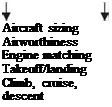
Much of the work in the conceptual study phase can be streamlined through a good market study to identify a product line within a company’s capabilities. In this phase, findings of the market study are developed with candidate configura­tions; the technology to be adopted is firmed up and the economic viability is final­ized. This is accomplished through aircraft sizing, engine matching, preliminary weight estimation, and evolution of a family of aircraft with payload and range combinations (i. e., aircraft performance) for all configurations. Planning portfolios with budgetary provisions, manpower requirements, progress milestones, potential subcontract/risk-sharing partners’ inputs, and so forth are included as the starting point of the design process. In general, at the end of this phase, management deci­sion for a go-ahead is expected with a final configuration selected from the candidate configurations offered. Continuous interaction with potential customers (i. e., oper­ators and subcontractors) occurs during this phase, with the objective of arriving at a family of aircraft as the most “satisfying” design with compromises rather than an

Phase 1: Conceptual Study Phase (Feasibility Study)

Combat If technology demonstrator time is included, then it could take a decade.

Aircraft Flight-testing time would be about twice that of large civil aircraft because

of weapons and systems integration of many new technologies.

Military aircraft projects have large variations.

Chart 2.4. Typical project time frame “optimum” solution. Management may request a level of detail (e. g., risk analysis) that could extend the study phase or flow into the next phase, thereby delaying the go-ahead decision to the early part of Phase 2. This is likely if the candidate aircraft configurations are short-listed instead of finalized. For those designers who have planned ahead, Phase 1 should finish early – especially if they are well versed in the product type and have other successful designs in their experience.

Phase 2: Project Definition Phase (Preliminary Design)

This phase begins after the go-ahead has been given to a project, and a “point of no-return” is reached during this phase. Project definition sometimes may overlap with the detailed design phase (i. e., Phase 3). During the advanced design phase, the project moves toward a finer definition, with a guarantee that the aircraft capabili­ties will meet if not exceed the specifications. Some iteration invariably takes place to fine-tune the product. Details of the technology level to be used and manufac­turing planning are essential, and partnership outsourcing is initiated in this phase. Procurement cost reviews and updates also are ongoing to ensure that project via­bility is maintained. Many fine aircraft projects have been stalled for lack of proper
planning and financial risk management. (Readers may study recent case histories of products such as the Swearingen SJ30 [now certified and under production] and the Fairchild-Dornier 928.) The beginning of metal cutting and parts fabrication as well as deliveries of bought-out items (e. g., engine and avionics) must be completed in Phase 2. In this phase, extensive wind-tunnel testing, CFD analysis, detailed weights estimation, detailed structural layout and FEM analysis, system definitions, produc­tion planning, and so forth are carried out.

Phase 3: Detailed Design Phase (Full-Scale Product Development)

In this phase, manufacturers push toward completion – when peak manpower is deployed for the project. Normally, projects cannot sustain delay – time is money. All aspects of detailed design and systems architecture testing are completed in this phase. (The test rig is called an “iron bird” – it simulates full-scale control and sys­tem performance.) At the end of Phase 3, the aircraft assembly should near, if not achieve, completion.

Phase 4: Final Phase (Certification)

Phase 4 must start with the rapid completion of the aircraft assembly for ground­testing of installed systems and other mandatory structural strength-testing to pre­pare for flight-testing. In general, two to four aircraft are needed to complete nearly 200 to 800 flight-testing sorties (depending on the type of aircraft) toward substan­tiation for certification of the airworthiness standard. At this stage, there should be no major setbacks because the engineers have learned and practiced aircraft design well with minimal errors.

Each project has a characteristic timeline; – this book uses a 4-year project time. Remember, however, that some projects have taken more or less time. Section 2.4.2 is a detailed breakdown of a small aircraft project for a small or medium company. The author recommends that similar detailed milestone charts be drawn for course – work projects to give an idea of the manpower requirements.